Fouling of tube bundles under pool boiling conditions
Chemical Engineering Science60(2005)1503–
1513
https://www.360docs.net/doc/932351572.html,/locate/ces
Fouling oftube bundles under pool boiling conditions
M.R.Malayeri a,?,H.Müller-Steinhagen b,T.H.Bartlett c
a Institute of Technical Thermodynamics,German Aerospace Centre,Pfaffenwaldring38-40,D-70569Stuttgart,Germany
b Institute of Technical Thermodynamics,German Aerospace Centre,Institute for Thermodynamics and Thermal Engineering,
University of Stuttgart Pfaffenwaldring38-40,D-70569Stuttgart,Germany
c Department of Chemical an
d Materials Engineering,University of Auckland,New Zealand
Received19July2004;received in revised form14October2004;accepted31October2004
Available online30December2004
Abstract
This paper aims to provide experimental heat transfer results for boiling of CaSO4solutions on the outside oftube bundles,and also to shed some light into the mechanisms which in?uence heat transfer fouling under pool boiling conditions.Heat transfer coef?cients for three heater rods with an identical diameter of10.67mm on a35mm vertical pitch have been measured.The independent variables bulk concentration and heat?ux have been varied from0.8to1.6g/L and33to300kW/m2,respectively.The experimental results show that the mechanisms of fouling on the middle and top heater substantially differ from those at the bottom heater,due to the dominant effects of bubble impingement on the heat transfer surfaces.In particular,the competing effects on the degree of wall superheat and the supersaturation of the boiling liquid play a signi?cant role.Spalling effects are more pronounced on the upper heaters where thin,friable deposits were found with low density and adherence,particularly at higher heat?uxes and lower concentrations.In terms of tube bundle ef?ciency,the best results were found for lower concentrations.
?2004Elsevier Ltd.All rights reserved.
Keywords:Fouling;Heat transfer;Crystallisation;Pool boiling;Tube bundle;Heat exchangers
1.Introduction
Heat transfer fouling is an undesirable process in which unwanted materials with low thermal conductivity deposit on heat transfer surfaces.Several forms of fouling exist based on the chemical/physical conditions under which the deposit layer forms.One of the most severe forms of foul-ing occurs during pool boiling heat transfer(Jamialahmadi et al.,1989).Such conditions arise in many heat exchangers in which nucleate boiling is the dominant process;perhaps kettle reboilers and steam generators provide the most spec-tacular examples.In such devices,fouling of heat transfer surfaces causes signi?cant cost penalties,due to both re-duction in heat transfer coef?cient and increases in boiler metal wall temperature in order to provide the increased temperature differential necessary to overcome the fouling ?Corresponding author.Tel.:+49471168628365;
fax:+497116862712.
E-mail address:m.malayeri@dlr.de(M.R.Malayeri).
0009-2509/$-see front matter?2004Elsevier Ltd.All rights reserved. doi:10.1016/j.ces.2004.10.017resistance.Increasing boiler metal temperature also results in a rapid utilisation ofthe lif e ofthe components with possible creep rupture,ifthe temperature increase is too high.As a result,such devices often require costly shutdowns for inspection and removal off ouling deposits.
Several investigators have studied the mechanisms of fouling on single tubes during nucleate boiling(Partridge and White,1929;Freeborn and Lewis,1962;Hospeti and Mesler,1965;Palen and Westwater,1966;Jamialahmadi et al.,1989,1993;Bornhorst et al.,1999).Jamialahmadi and Müller-Steinhagen(1993),in a review paper,reported that the primary causes of fouling for solutions with inverse solubility are supersaturation as well as bubble formation behaviour.It is also stated that the following steps take place when a deposit layer forms on the surface of a single tube during pool boiling:
?Bubble nuclei form just above the nucleation sites that are available on the surface.Bubble density is directly
1504M.R.Malayeri et al./Chemical Engineering Science60(2005)1503–1513
proportional to the number ofnucleation sites,and hence the surface material and roughness are of prime importance.
?Bubble agitation initially produces considerable turbu-lence that enhances heat transfer.In this phase,bubble characteristics such as size,shape and rise velocity are af-fected by the physical/chemical properties of the boiling liquid,notably surface tension.
?Beneath the bubbles,a microlayer exists,in which the concentration ofthe dissolved salt is increased due to the pref erential evaporation ofthe solvent.Ifthe dissolved salt has an inverse solubility relationship with temperature, the considerable temperature gradient in the microlayer leads to further supersaturation of the solution.Under such circumstances,crystal nuclei will begin to precipitate on the surface and a deposit layer builds up,initially in the form of concentric rings around the nucleation sites.Both surface temperature and bulk concentration dominate the formation and thickness of the fouling layer in this phase. Knowledge oflocations in tube banks,where deposit has accumulated can aid in planning and targeting locations for cleaning and removal ofdeposits.Such inf ormation is linked to the understanding ofthe mechanisms ofthe f ouling pro-cess on tube bundles during pool boiling.Nevertheless,pub-lished studies to-date have been undertaken for single tubes or wires,while the authors are not aware ofany systematic information on fouling of tube bundles.The present study aims to investigate experimentally mechanisms off ouling under pool boiling conditions for inverse solubility salts, such as CaSO4.The experiments have been performed with three test heater rods arranged vertically above each other in a pool ofliquid,f or various bulk concentrations and heat ?uxes.One ofthe main aims ofthe investigation was the determination of the change in fouling from the bottom to the top heater.Ofparticular importance f or design and oper-ation is information about the interaction between the heat transfer mechanisms on the different tubes,which is dis-cussed in terms ofbundle ef?ciency.Finally,Scanning Elec-tron Microscope(SEM)analysis is provided to discern the structure of deposit for different bulk concentrations and heat?uxes.
2.Experimental set-up and procedure
2.1.Equipment and data acquisition
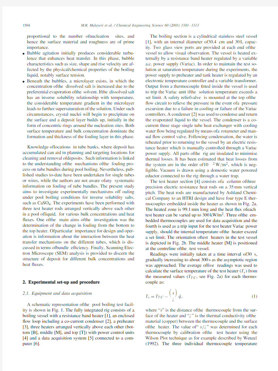
A schematic representation ofthe pool boiling test f acil-ity is shown in Fig.1.The fully integrated rig consists of a boiling vessel with a resistance band heater[1],an enclosed ?ow loop including a co-current condenser[2],a preheater [3],three heaters arranged vertically above each other(bot-tom[B],middle[M],and top[T])with power control units [4]and a data acquisition system[5]connected to a com-puter[6].
The boiling section is a cylindrical stainless steel vessel [1],with an internal diameter of30.4cm and30L capac-ity.Two glass view ports are provided at each end ofthe vessel to allow visual observation.The vessel is heated ex-ternally by a resistance band heater regulated by a variable a.c.power supply(Variac).In order to maintain the test so-lution at saturation temperature during the experiments,the power supply to preheater and tank heater is regulated by an electronic temperature controller and a variable transformer. Output from a thermocouple?tted inside the vessel is used to trip the Variac unit ifthe solution temperature exceeds a set limit.A saf ety reliefvalve is mounted at the top ofthe ?ow circuit to relieve the pressure in the event ofa pressure excursion due to a failure in cooling or failure of the Variac controllers.A condenser[2]was used to condense and return the evaporated liquid to the vessel.The condenser is a co-current three stage single tube heat exchanger with cooling water?ow being regulated by means ofa rotameter and man-ual?ow control valve.Following condensation,the water is reheated prior to returning to the vessel by an electric resis-tance heater which is manually controlled through a Variac power supply.All parts ofthe rig are insulated to minimise thermal losses.It has been estimated that heat losses from the system are in the order of10?2W/m2,which is neg-ligible.Vacuum is drawn using a domestic water powered eductor connected to the rig through a water trap.
The test heater section[4]consists ofa column ofthree precision electric resistance heat rods on a35mm vertical pitch.The heat rods are manufactured by Ashland Chemi-cal Company to an HTRI design and have four type E ther-mocouples embedded inside the heater as shown in Fig.2a. The heated zone is99.1mm long and the heat?ux ofeach test heater can be varied up to300kW/m2.Three ofthe em-bedded thermocouples are used for data acquisition and the fourth is used as a trip input for the test heater Variac power supply,should the internal temperature ofthe heater exceed a set limit.The orientation oftest heaters in the test vessel is depicted in Fig.2b.The middle heater[M]is positioned at the centreline ofthe test vessel.
Readings were initially taken at a time interval of30s, gradually increasing to about300s as the asymptotic region was approached.The average of?ve readings was used to calculate the surface temperature of the test heater(T s)from the measured values(T T C,see Fig.2a)for each thermo-couple as:
T s=T T C?
s
˙q,(1)
where“s”is the distance ofthe thermocouple f rom the sur-face of the heater and“ ”is the thermal conductivity ofthe material(copper)between the thermocouple and the surface ofthe heater.The value of“s/ ”was determined for each thermocouple by calibration ofthe test heater using the Wilson Plot technique as for example described by Wenzel (1992).The three individual thermocouple temperature
M.R.Malayeri et al./Chemical Engineering Science60(2005)1503–15131505
Band heater
Data recorder (D)
[1]
[5]
[6]
Fig.1.Schematic representation oftest rig.
Heater
element
T TC
(b)
Fig.2.(a)HTRI test heater,(b)schematic drawing oftest heater orientation
in the vessel.
differences(see Fig.2a)were averaged to give the average
surface temperature using
T s=1
3
3
i=1
T T C,i?
s
i
˙q
.(2)
The average heat transfer coef?cient was then determined
using
=
˙q
s b
,(3)
where T b is the bulk temperature.The fouling resistance
due to deposition ofa f ouling layer is then calculated as a
function of time from
R f=
T s?T b
˙q
t
?
T s?T b
˙q
.(4)
The subscripts“t”and“0”denote conditions at any time and
at the beginning ofthe experiment when the heat exchanger
is considered to be clean,respectively.
2.2.Preparation of test solutions
Test solutions ofcalcium sulphate were prepared by dis-
solving calcium sulphate hemi-hydrate(CaSO4.1
2
H2O)in
a separate container.In all cases,distilled water was used
as solvent.The calcium sulphate was mixed sparingly with
water and washed into the plastic container.Ifsolid lumps
ofcalcium sulphate were f ound these were broken up and
added to the container again.The1400rpm stirrer was then
switched on for about24h.Following mixing the calcium
sulphate solution was left for at least24h,so that any undis-
solved matter could settle out.The concentration was mea-
sured through a sample line,just before applying power to
the test heaters and also after each run.
2.3.Experimental procedure
The test vessel was cleaned prior to each run by removing
the front view port and scraping any scale from the vessel
1506M.R.Malayeri et al./Chemical Engineering Science60(2005)1503–1513 Table1
Range ofoperating parameters
CaSO4concentration[g/L]
1.6 1.20.8
Heat?ux,(kW/m2)
33+
55+
76+
105++
145+++
200++
300+++
walls.Each run starts with introducing the test solution to
the vessel once the vacuum pump had reduced the system
pressure to approximately10kPa.The principal reason for
this was to give a measure ofdegassing ofthe test solution
during?lling ofthe vessel.The vessel band heater was then
turned on to preheat test rig and solution to the saturation
temperature.Meanwhile,the condenser had also to be turned
on to establish steady-state conditions.The vacuum pump
was used at regular intervals to maintain the pressure and
to remove residual gases which desorbed from the solution.
After approximately3h preheating,the test solution reached
the saturation temperature.Then,the power supply to the
test heaters was turned on and set to a de?ned value.At
the same time,the data acquisition system was started to
record temperatures,pressure and heat?uxes.The range of
operating parameters used in this investigation is given in
Table1.
It should be noted that the saturation concentration of
CaSO4.1
2H2O at100?C is1.6g/L.Any deposition occurring
at lower bulk concentrations has to be associated with local concentration effects in the vicinity of the growing bubbles.
2.4.Error analysis
The systematic experimental errors for the determination of heat transfer coef?cients and fouling resistances are due to:
?errors ofapproximately±0.25K in temperature mea-surement
?an error ofabout±2%for determination of heat?uxes as a result ofsystematic errors in reading electrical volt-age and current.
Referring to Eq.(3),the largest error for the clean heat trans-fer coef?cients occurs for the smallest temperature differ-ence between surface and bulk.Based on the instructions in the ASME Journal ofHeat Transf er(Jamialahmadi and Müller-Steinhagen,1993),uncertainty with95%con?dence is estimated to be±9.65%.However,for fouling resistance measurements the uncertainty changes as a function of time due to changes in surface temperature when deposits start
to
02004006008001000120014001600
Time, [min]
H
e
a
t
t
r
a
n
s
f
e
r
c
o
e
f
f
i
c
i
e
n
t
,
[
W
/
m
2
K
]
Initial time, [min]
I
n
i
t
i
a
l
h
e
a
t
t
r
a
n
s
f
e
r
05101520
Fig.3.Typical variation of heat transfer coef?cient as a function of time (solid and open symbols correspond to complete run and initial period of 100min).
form on the surface.The maximum calculated uncertainty occurs at the start ofall runs when the temperature dif f er-ence is small.For instance,the uncertainty for the heat trans-fer measurements at the bottom heater for a typical con-centration of1.6g/L CaSO4and200kW/m2changes from 43.7%to10.35%when the fouling resistance increases from 0.008m2K/kW to0.16m2K/kW.
3.Results and discussion
3.1.Heat transfer fouling on a single test heater
Calcium sulphate has an inverse solubility and thus with increasing temperature,the solubility decreases.The satura-tion concentration ofcalcium sulphate at100?C is approx-imately1.6g/L.With increasing surface temperature as the result ofthe adjusted heat?ux,the solution becomes su-persaturated.Due to local evaporation effects during bubble formation,a further increase in concentration by up to a fac-tor of3–4may occur(Jamialahmadi and Müller-Steinhagen, 2004a,b).Under such supersaturated conditions,the dis-solved salt will start to precipitate at the heat transfer surface after an initial surface conditioning period.
Fig.3illustrates the typical variation ofheat transf er coef?cient as a function of time for a single heater(bot-tom position),a concentration of1.2g/L and a heat?ux of 300kW/m2.Open circles represent data for the initial period up to20min which are dif?cult to identify in the complete experimental run,which is shown as solid circles.It is evi-dent that the heat transfer coef?cient drops rapidly[region I]followed by a gradual recovery to a secondary maximum [region II]which in turn is followed by a more gradual de-cline towards an asymptotic value ofabout6000W/m2K [region III].
The fouling process during nucleate boiling strongly depends on bubble characteristics such as size,shape,
M.R.Malayeri et al./Chemical Engineering Science60(2005)1503–15131507 Table2
Thermal conductivity(wet)and density(dry)ofdeposit layer f rom a
CaSO4concentration of1.2g/L on a single heater(Jamialahmadi and
Müller-Steinhagen,1993)
Heat?ux(W/m2)Thermal conductivity(W/m K)Density(kg/m3)
96310.751270
192610.851870
28892 1.092120
77045 2.12420
249964 2.092429
301204 2.22445
departure frequency and bubble rise velocity.In the initial period[region I]hemispherical bubbles with a large con-tact area are clearly visible.The bubble size during this time ranged from10to20mm in diameter with a bubble frequency of5–7bubbles per second.In regions II and III, bubbles were spherical with a uniform diameter of2mm, and the bubble departure frequency is much higher than that ofregion I.Jamialahmadi and Müller-Steinhagen(1993) have reported the same phenomena and found that changes in bubble growth mechanisms were related to the calcium sulphate deposition.The highest deposition rate occurs in the microlayer beneath the bubble.Deposits under the bub-bles have high density and adherence and tend to reduce local heat transfer,leading to the initial rapid drop in heat transfer coef?cient.Subsequently,the porous deposits form-ing around the original nucleation sites provide additional bubble nucleation sites which give rise to the observed recovery ofheat transf er coef?cient in region II.Bubbles that are generated above these new nucleation sites and the associated additional turbulence caused by these smaller bubbles improve the heat transfer coef?cient further.
As the deposition process continues,the deposited layer increases in thickness and compactness,causing deactivation ofnucleation sites.Jamialahmadi and Müller-Steinhagen (1993)experimentally measured the density and thermal conductivity of the fouling layer for different heat?uxes dur-ing boiling on a single heater.Table2summarises these mea-surements,which show that the deposit layer is more dense at higher heat?uxes which is the case in Fig.3(300kW/m2). Furthermore,bubbles start to form at the interface between the deposit and solution rather than at the metal heat transfer surface.Since the interfacial tension between the calcium sulphate deposit and the solution(≈0.045N/m)is much lower than that between metal and solution(≈0.069N/m), smaller bubbles are formed.The heat transfer coef?cient de-creases due to the combined ef f ect ofthe growth ofa ho-mogeneous deposit layer and the deactivation ofnucleation sites,until?nally a constant asymptotic value is reached.
3.2.Heat transfer fouling on the test tube bundle Fouling processes on tube bundles are more complex than those on single tubes,due to the substantial turbulence
1000
2000
3000
4000
5000
6000
7000
8000
9000
10000
0100020003000400050006000
Time, [min]
H
e
a
t
t
r
a
n
s
f
e
r
c
o
e
f
f
i
c
i
e
n
t
,
[
W
/
m
2
K
] C = 6.1g/L
q = 33 kW/ m2Bottom(1) Middle (2)Top (3)
(1)
(3)
(2)
.
-2.5E-04
-2.0E-04
-1.5E-04
-1.0E-04
-5.0E-05
5.0E-05
1.0E-04
1.5E-04
2.0E-04
0100020003000400050006000
Time, [min]
F
o
u
l
i
n
g
r
e
s
i
s
t
a
n
c
e
,
[
m
2
K
/
W
]
(a)
(b)
Fig.4.(a)Heat transfer coef?cient versus time,1.6g/L CaSO4,33kW/m2.
(b)Fouling resistance versus time,1.6g/L CaSO4,33kW/m2.
caused by bubbles rising from the lower heat transfer sur-faces,which impinge on and slide around the upper tubes. This will result in substantial changes in the fouling mech-anisms due to the distribution ofwall shear stresses.
For heat?uxes of105kW/m2(T s=107.4?C)and below, bubbles from the bottom heater enhanced the heat transfer coef?cients at the two upper test heaters,which additionally did not show any dense and adherent scale.Fig.4a shows parallel measurements of the heat transfer coef?cients for all three test heaters,as a function of time for a heat?ux of33kW/m2and a salt concentration of1.6g/L CaSO4.All three heaters have the same surface characteristics,such as material and mean surface roughness of0.407 m.It is ev-ident in this?gure that the middle[M]and top[T]heaters show an increase in heat transfer coef?cient,while the bot-tom heater[B]exhibits only a marginal decrease in heat transfer coef?cient.The heat transfer enhancement is partic-ularly pronounced for the top heater,where the heat transfer coef?cients are twice as high as for the middle heater.Fig. 4b demonstrates that the thermal fouling resistances either remained around0m2K/W(bottom heater)or even became negative(middle and top heaters),the latter being an arti-fact of the de?nition of R f according to Eq.(4)and the
1508M.R.Malayeri et al./Chemical Engineering Science 60(2005)1503–1513
H e a t t r a n s f e r c o e f f i c i e n t , [W /m 2K ]0
1.0E-05
2.0E-05
3.0E-05
4.0E-05
5.0E-05
6.0E-05
7.0E-05Time, [min]
F o u l i n g r e s i s t a n c e , [m 2K /W ]
(a)
(b)
Fig. 5.(a)Heat transfer coef?cient versus time,0.8g/L CaSO 4,300kW/m 2.(b)Fouling resistance versus time,0.8g/L CaSO 4,300kW/m 2.
bubble-related improvement in heat transfer.This is an ef-fect of the signi?cant shear forces generated by the bubbles from the lower heaters ?owing across the upper test heaters.Observations showed that any scale formed on the middle and top heaters subsequently re-dissolved in the test solu-tion.The very thin deposits on the bottom heater were ini-tially white and gradually developed into yellowy brown.At heat ?uxes above 105kW/m 2,the fouling resistance increased also for the middle and top heaters and,unless the scale deposits broke off the heater surfaces,dense and ad-herent deposits formed.Figs.5a and b depict the heat trans-fer coef?cients and fouling resistances as a function of time for 300kW/m 2and a sub-saturated concentration of0.8g/L.Fouling started at the bottom ofthe lowest heater where only relatively few bubble nucleation sites and large bubbles were seen.It then developed at the upper side ofthe middle heater and ?nally a slight amount ofscale also f ormed on the top heater.The middle heater had a thin,tenacious and almost transparent scale on the top which was comparatively rough.This rough surface would have provided more bubble nu-cleation sites,hence generating more bubbles which would have led to heat transfer enhancement at the top heater.From visual observations,it was found that the upper side of the
005001000150020002500300035004000
Time, [min]
H e a t t r a n s f e r c o e f f i c i e n t , [W /m 2K ]
Fig.6.Heat transfer coef?cient as a function of time for different con-centrations and 300kW/m 2.
middle heater was covered with circular scale rings,which had formed around the sites where bubbles had nucleated.The top heater had small circular scale rings on top,uneven scale in the middle section and very thin scale at the bot-tom.The formation of circular scale rings is consistent with observations of Freeborn and Lewis (1962).
3.2.1.Effect of CaSO 4concentration
The movement of bubbles after detachment from the heat transfer surface generates considerable agitation in the sur-rounding liquid.This promotes convection and decreases the thickness ofthe thermal boundary layer.Najibi et al.(1996)investigated the effect of CaSO 4concentration on heat trans-fer coef?cients for clean surfaces.They observed a relatively uniform bubble diameter of around 2mm and a low bub-ble departure frequency during pool boiling of distilled wa-ter at saturation temperature for low heat ?uxes (38kW/m 2which corresponds to a surface temperature of 105.7?C).As the concentration ofsalts with inverse solubility (such as CaSO 4)was increased from 0.253to 1.5g/L,the number of active bubble nucleation sites decreased and the bubble de-parture diameter increased from 2.1mm to 3.2mm.There-fore,the increasing CaSO 4concentration results in lower heat transfer coef?cients due to changes in the mechanisms ofbubble f ormation associated with the changing physical properties ofthe solution,particularly surf ace tension.At
high heat ?uxes (300kW/m 2which corresponds to a surface
temperature of114.1?C),however,bubble breakup occurs,giving rise to small and almost undistinguishable individual rigid bubbles.Formation ofthese small bubbles and their subsequent release into the surrounding liquid enhances con-vection currents around the heater and as a result the heat transfer coef?cient.
Fig.6illustrates the deposition-related changes in heat transfer coef?cient as a function of CaSO 4concentration,for a constant heat ?ux of 300kW/m 2.This ?gure only depicts experimental data for the top and bottom heaters,as examples for operating conditions with and without effects
M.R.Malayeri et al./Chemical Engineering Science 60(2005)1503–15131509
02000
40006000800010000120000
1000
2000
300040005000
6000
Time, [min]
H e a t t r a n s f e r c o e f f i c i e n t , [W /m 2K ]
Fig.7.Heat transfer coef?cient of bottom heater as a function of time for different heat ?uxes and 1.6g/L.
ofupward bubble ?ow on the f ouling process.For both heaters,the heat transfer coef?cients decreases more rapidly as the CaSO 4concentration was increased.This is at-tributed to the increased supersaturation ofthe salt solution at the triple interface of vapour,liquid and heat transfer surface.The measurements also con?rmed the observations of Najibiet al.(1996),i.e.,that an increase in CaSO 4con-centration results in bigger bubbles.Interestingly,the effect ofCaSO 4concentration on the deposition-related drop in heat transfer coef?cient is more pronounced for the bottom heater,while only a small difference between the concen-trations of0.8and 1.2g/L can be seen f or the top heater.At the saturation concentration of1.6g/L,the power input to the heaters had to be terminated fairly early,due to an excessive increase in temperature caused by the rapid for-mation ofdeposits on the surf aces.For the 1.2g/L solution,this was required only after 2500min.
3.2.2.Effect of heat ?ux
The variation of heat transfer coef?cient for different heat ?uxes and a constant salt concentration of1.6g/L is illus-trated in Fig.7for the bottom heater.All ?ve data sets ex-hibit the same trend as already shown in Fig.3,i.e.,three regions starting with a rapid decrease,followed by a recov-ery to a plateau (both regions together may be termed initial period or delay time)and ?nally a gradual reduction towards an asymptotic value.In the initial period,heat transfer coef-?cients depend strongly on the heat ?ux.Furthermore,the initial time decreases as the heat ?ux increases;for this rea-son,regions I and II cannot clearly be distinguished in Fig.7.For example,for 33kW/m 2it is about 1300min,while it is only 20min for 300kW/m 2.The dependency ofheat transfer coef?cient on heat ?ux is less important as time goes on,in particular for heat ?uxes below 105kW/m 2,due to the dominating in?uence ofthe thermal resistance ofthe deposit layer.The examination ofother data-sets f or lower concentrations did not show the same trend.The effect of
02000
40006000
800010000120000
1000
2000
300040005000
6000Time, [min]
H e a t t r a n s f e r c o e f f i c i e n t , [W /m 2K ]
Fig.8.Heat transfer coef?cient of top heater as a function of time for different heat ?uxes and 1.6g/L.
heat ?ux may be explained by analysing the mechanisms of bubble nucleation.
Pool boiling can only occur when the heated surface con-tains very small pits and cracks known as “cavities”,that are required for bubble nucleation.A cavity can ideally be imagined as being conical and having a circular opening.For non-fouling pool boiling on clean metal surfaces,Whalley (1996)proposed the following equation for the prediction ofthe cavity radius:R =
2 T sat
g h v T superheat
.
(5)
In this equation,R is the cavity radius, the surface ten-sion, g the density ofthe vapour and h v the latent heat ofevaporation.The equation indicates that as the wall su-perheat increases,more cavities ofsmaller radius are able to become active,giving rise to a higher heat transfer rate.The same mechanism applies at the start off ouling process when both degree ofwall superheat and number ofnucle-ation sites dominate the development ofthe additional ther-mal resistance.
Fig.8shows experimental data from the same run as shown in Fig.7,but this time for the top heater.Obviously,not all data sets follow the same trend as shown in Figs.3and 7.While comparable trends may be observed for the higher heat ?uxes of200and 300kW/m 2,for lower heat ?uxes,the top heater is experiencing a continuous heat transfer en-hancement.This implies that while both,the degree ofwall superheat and the number ofnucleation sites still play a role in the mechanism of heat transfer,the main parameters for the upper heaters are the ?ow ofdeparting bubbles f rom the lower heaters and the way they impinge on the surfaces of the upper heaters.The effect of the bubbles is three-fold:they cause more turbulence when impinging on the surface,they sweep away bubbles which otherwise would have a longer residence time at the surface,and they possibly scour the frail deposit layer on the upper heaters.These effects
1510M.R.Malayeri et al./Chemical Engineering Science 60(2005)1503–
1513
Fig.9.Bubble behaviour and impingement on the upper heaters during a typical fouling run,200kW/m 2and 1.2g/L CaSO 4.
50
100
150200250
300
350
Heat flux, [kW/m
2]F o u l i n g r a t e ×108, [m 2K /J ]
Fig.10.Fouling rate as a function of heat ?ux for a given concentration of1.6g/L f or bottom and top heaters,respectively.
are,however,only dominant for low heat ?uxes,which are characterized by low nucleation site densities and large bub-bles.For higher heat ?uxes with a high degree ofwall super-heat,the bubbles originating from the heat transfer surfaces are dominating the mechanisms ofheat transf er,and the heat transfer coef?cients follow the same trend as those for the bottom heaters.Fig.9puts the above-mentioned mech-anisms into perspective,which shows bubble behaviour in the vessel during a fouling run for a heat ?ux of 200kW/m 2and 1.2g/L CaSO 4.Apparently,bubble impingement on the top heater prevents formation of any deposit layer while a visible scale layer has formed on the bottom heater.
The experiments already shown in Figs.7and 8are pre-sented in Fig.10in terms ofa f ouling rate de?ned as ˙R
f =R f,t 2?R f,t 1
t 2?t 1
(6)
for the bottom and top heaters as a function of heat ?ux.In Eq.(6),t 1and t 2correspond to the time at the start and the end ofregion II (see Fig.3),i.e.,the time span over which
the main changes in heat transfer occur.Negative values of the fouling rate indicate conditions,where the measured heat transfer coef?cients actually increased due to the formation ofadditional bubble nucleation sites as a result ofsome mi-nor deposit.All fouling rates are determined from the exper-imental data for a saturation concentration of 1.6g/L.Both heaters exhibit similar trends,but the top clearly bene?ts more from the additional bubble nucleation site formation at low heat ?uxes and suffers less from severe scale formation at higher heat ?uxes.For very high heat ?uxes,both heaters seem to approach the same fouling rate,indicating the less important effect of bubble impingement on the upper tube and instead the dominant effect of higher wall superheat that leads to rapid formation of deposit layers.
3.2.3.Bundle ef?ciency
The design ofheat exchangers operating under pool boil-ing conditions requires information about the best way to arrange the tubes in the bundle,in order to achieve the max-imum heat transfer rate per unit area.The bundle effect,which is mainly used for clean heat exchangers,is de?ned as the ratio heat transfer from an upper tube to that from a lower tube,as ifthe lower tube was activated alone in the bundle,in the absence ofany possible ?ow turbulence caused by generation ofbubbles on the upper tubes.For clean pool boiling and at high heat ?uxes,Cornwell (1988)showed that convection effects as well as bubbles from lower tubes im-pinging on,and sliding around,upper tubes can account for bundle effects above one,and that bubble nucleation only oc-curs on the lower tubes.Memory et al.(1995)reported that the bundle effect is minimised by the achievement of maxi-mum turbulence in the bulk ?ow.With respect to the present investigations on scale formation,a bundle ef?ciency can be de?ned as the ratio of the heat transfer coef?cients for top tubes ofthe bundle to those f or the bottom tubes,once the bundle has reached its asymptotic fouling resistance.In this study,the bundle ef?ciency is used because information on activated single heaters,which is required for the calculation ofthe bundle ef f ect,is not available.
Fig.11shows the bundle ef?ciency as a function of heat ?ux for concentrations of 0.8,1.2,and 1.6g/L CaSO 4.This value is calculated using heat transfer coef?cients in the asymptotic region where the changes in fouling resis-tance with time are insigni?cant.For heat ?uxes above 150kW/m 2,the bundle ef?ciency decrease with increas-ing CaSO 4concentration.Interestingly,the curves for 1.2and 1.6g/L pass through a maximum which,however,is much more pronounced for the higher concentration.The curve for 0.8g/L does not display the same trend within the investigated range ofheat ?uxes,since no experiments were carried out for this concentration below 145kW/m 2due to the absence off ouling at such low heat ?uxes and low concentrations (Jamialahmadi et al.,1989).For the saturation concentration of1.6g/L and at low heat ?uxes the main effect of the generated bubbles is to increase heat
M.R.Malayeri et al./Chemical Engineering Science 60(2005)1503–15131511
1.5
2.5
3.50
50
100
150200250
300350
Heat flux, [kW/m 2]
αT / αB , [-]
Fig.11.Bundle ef?ciency as a function of heat ?ux for different concen-trations.
transfer through additional turbulence.As shown in Fig.10,fouling rates for these conditions are very small or even declining.With increasing heat ?ux,i.e.,increasing number ofbubbles,the bundle ef ?ciency continues to increase up to a maximum.The bundle ef?ciency then starts to decline for two reasons:(i)developed nucleate boiling at the upper heaters reduces the effect of rising bubbles and (ii)a sub-stantial deposit layer starts to form,initially at the lower heaters.This can be seen by comparison of Figs.7and 8for heat ?uxes below 105kW/m 2,where only the bottom heater experiences a deposit-related drop in heat transfer,whereas the values for the top heater remained virtually constant.Somewhere between 105and 150kW/m 2,the ef-fect of deposition also shows for the top heater,giving rise to an even accelerated drop in bundle ef?ciency.
For the lower concentration of1.2g/L,the maximum bun-dle ef?ciency at 145kW/m 2is far smaller than that for 1.6g/L.The ?at maximum implies that the effect of turbu-lence caused by the generated bubbles on the heat trans-fer coef?cients of the top heater is less pronounced and that there is no delayed appearance off ouling deposits on the top heaters.This is con?rmed by the experimental ob-servations,showing that the bubble departure diameters at 1.2g/L CaSO 4are considerably smaller than for 1.6g/L and that only the bottom heater displayed a thin and friable de-posit layer,whereas the other two heaters stayed essentially deposit-free.The curve for 1.2g/L CaSO 4shows an unex-pected behaviour at 105kW/m 2,where the bundle ef?ciency is smaller than that for 1.6g/L.An examination of the ex-periments for this heat ?ux disclosed that the top heater remained clean for both concentrations of 1.2and 1.6g/L.However,the bottom heater for 1.6g/L CaSO 4experienced a considerably thicker fouling layer and hence a lower heat transfer coef?cient,which resulted in a higher bundle ef-?ciency.Fig.12compares the heat transfer coef?cients of both,bottom and top heater,for the two concentrations of 1.2and 1.6g/L.
2000
400060008000100001200001000
200030004000
Time, [min]
H e a t t r a n s f e r c o e f f i c i e n t , []W /m 2K ]
https://www.360docs.net/doc/932351572.html,parison ofheat transf er coef ?cient between bottom and top heaters for two concentrations of 1.2and 1.6g/L and constant heat ?ux of105kW/m 2.
11.21.41.61.822.22.40.6
0.8
1 1.
2 1.4 1.6 1.8
CaSO 4 concentration, [g/L]
αT / αB , [ -]
Fig.13.Bundle ef?ciency as a function of concentration for different heat ?uxes.
Fig.13highlights the effect of CaSO 4concentration on the bundle ef?ciency,for two heat ?uxes of 145and 200kW/m 2.The ?gure indicates that CaSO 4concentration has only a marginal impact on bundle ef?ciency when it changes from 0.8to 1.2g/L,i.e.,for sub-saturation conditions.However,the bundle ef?ciency reduces strongly when the concentra-tion increases from 1.2to 1.6g/L.This behaviour is con-sistent for both heat ?uxes,but the bundle ef?ciency is somewhat higher for the lower heat ?ux of 145kW/m 2.In summary,experimental results in this section show con-vincingly that fouling resistances obtained from single-tube experiments cannot be applied to tube bundles,since this would lead to excessive over-design.Furthermore,the results may hint to innovative design approaches,where the lowest tubes in the bundle are,at a higher cost,manufactured with low fouling surfaces (Müller-Steinhagen and Zhao,1997).Trends reported in the present investigation may,with the
1512M.R.Malayeri et al./Chemical Engineering Science 60(2005)1503–
1513
Fig.14.SEM pictures of deposit structure from the bottom heater for different heat ?ux and concentrations.
appropriate caution,be extrapolated to similar operating con-ditions.There are no doubts,however,that a lot ofadditional work is necessary to understand the mechanisms off ouling with and without bubble formation.
3.2.
4.Deposit morphology
The deposit morphology was determined using a SEM (Hitachi S-3200N,Resolution 3.5nm and with a magni?ca-tion range between 20×and 200,000×).All samples were taken at the end ofthe respective experiments,with great care to avoid distortion ofthe deposit structure.For this purpose,vessel was cooled down and the test heaters re-moved carefully and placed temporarily into another vessel that contained distilled water at ambient temperature.The heater was then dried and with the use ofa sharp blade,the rigid deposit layer was carefully separated from the surface.It was found that the structure of calcium sulphate was in?uenced by both concentration and heat ?ux.Fig.14presents some typical SEM pictures for different concentra-tions and heat ?uxes for the bottom heater.For the CaSO 4concentration of1.2g/L at 105kW/m 2,the structure is rather porous with a large number ofdistorted dome-shaped crys-tals.This structure becomes much denser for the higher heat ?ux of300kW/m 2.There is no signi?cant difference in the range ofcrystal sizes f or the two heat ?uxes;the distinctive feature is the evolution of the crystal shape.
For a CaSO 4concentration of1.6g/L,the deposit struc-ture in terms ofshape,size and crystal arrangement is en-tirely different than for 1.2g/L.Crystals for 300kW/m 2are much smaller than those for 33kW/m 2and their orientation shifts from perpendicular to parallel with respect to the di-rection ofbubble growth.In general,crystals f or higher heat ?uxes are denser,harder,more compact and more adherent than those for lower heat ?uxes.
4.Conclusions
Measurements presented in this paper highlight some im-portant features of scale formation processes in tube bundles.The heater at the lowest position in the tube arrangement ex-perienced a deposit layer in all experiments with CaSO 4con-centrations above or equal to 0.8g/L,but less signi?cantly for lower heat ?uxes and bulk concentrations.Deposits on the bottom heater in general were rather dense and adherent as shown in Table 2as well as Fig.14.For heat ?uxes of 105kW/m 2or below,the thermal fouling resistances for the top and middle heaters either remained zero or even negative (i.e.,an increase in heat transfer due to increased bubble for-mation on the bottom heater).In cases where a thin deposit layer was formed,it was very porous,friable and could be removed easily.For a CaSO 4concentration of1.6g/L and
M.R.Malayeri et al./Chemical Engineering Science60(2005)1503–15131513
heat?uxes above145kW/m2,the heat transfer coef?cient also decreased for the middle and top heaters.
The frequency,density and size of bubbles generated on the bottom heater has a substantial impact on the heat trans-fer enhancement of the middle and top heaters.Bubble ag-itation does not only increase heat transfer through higher local shear forces,but may also reduce the local supersat-uration in the vicinity ofbubbles nucleating on the upper heaters.Ifany deposition occurred on the top heaters,then the deposits were only formed on the upper side.The effect ofbubble agitation is considerably more signi?cant at lower concentrations and higher heat?uxes due to the larger num-ber ofbubbles that generate turbulence and the higher like-lihood that this may scour some ofthe f rail deposit layers on the upper tubes(Fig.13).The CaSO4concentration also affects substantially the mechanism of heat transfer fouling. Increasing the heat?ux and,therefore the wall superheat, has two competing effects on pool boiling heat transfer to scale forming solutions.The increased bubble formation ac-tivity tends to increase the bundle heat transfer coef?cients and the shear forces on tube walls,which both reduce the formation of deposits.At the same time,local concentration and saturation effects tend to increase the rate of deposit for-mation.As a result,a maximum bundle heat transfer coef?-cient was observed for an intermediate heat?ux of around 100kW/m2,for the investigated experimental conditions. Notation
C concentration,g L?1
˙q heat?ux,W m?2
R cavity radius,m
R f fouling resistance,m2K W?1
˙R f fouling rate,m2K J?1
s distance ofthe thermocouple f rom the surf ace ofthe heater,m
t time,s
T temperature,K
Greek letters
heat transfer coef?cient,W m?2K?1
h v latent heat ofevaporation,J kg?1
T superheat degree ofwall superheat=T s?T sat,K
thermal conductivity,W m?1K?1
density,kg m?3
g vapour density inside bubble nucleus,kg m?3 surface tension,N m?1Subscripts
b bulk
B bottom heater
s surface
sat saturation
T topheater
TC thermocouple
References
Bornhorst,A.,Zhao,Q.,Müller-Steinhagen,H.,1999.Reduction ofscale formation by ion implantation and magnetron sputtering on heat transfer surfaces.Heat Transfer Engineering20(2),6–14.
Cornwell,K.,1988.The in?uence ofbubbly?ow on boiling f rom a tube in a bundle.Advances in pool boiling heat transfer,Proceedings of Eurotherm Seminar8,Paderborn,pp.177–183.
Freeborn,J.,Lewis,D.,1962.Initiation ofboiler scale f ormation.Journal ofMechanical Science4,46–52.
Hospeti,N.B.,Mesler,R.B.,1965.Deposits formed beneath bubbles during nucleate boiling ofradioactive calcium sulphate solutions.
A.I.Ch.E.Journal11,662–665.
Jamialahmadi,M.,Müller-Steinhagen,H.,1993.Scale formation during nucleate boiling—A review.Corrosion Reviews11(1&2),25–54. Jamialahmadi,M.,Müller-Steinhagen,H.,2004a.A new model for the effect of calcium sulfate scale formation on pool boiling heat transfer.
ASME Journal ofHeat Transf er126,507–517.
Jamialahmadi,M.,Müller-Steinhagen,H.,2004b.Journal ofheat transf er policy on reporting uncertainties in experimental and results,1993.
ASME Journal ofHeat Transf er115,5–6.
Jamialahmadi,M.,Bl?chl,R.,Müller-Steinhagen,H.,1989.Bubble dynamics and scale formation during nucleate boiling of aqueous calcium sulphate solutions.Chemical Engineering and Processing26, 15–26.
Memory,S.B.,Akcasayar,N.,Eraydin,H.,Marto,P.J.,1995.Nucleate pool boiling ofR-114and R-114-oil mixtures f rom smooth and enhanced surfaces II.Tube bundles.International Journal of Heat and Mass Transfer38(9),1363–1376.
Müller-Steinhagen,H.,Zhao,Q.,1997.Investigation oflow f ouling surf ace alloys made by ion implantation technology.Chemical Engineering and Science52,3321–3332.
Najibi,S.H.,Müller-Steinhagen,H.,Jamialahmadi,M.,1996.Boiling and non-boiling heat transfer to electrolyte solutions.Heat Transfer Engineering17(4),46–63.
Palen,J.W.,Westwater,J.W.,1966.Heat transfer and fouling rates during pool boiling ofcalcium sulphate solutions.Chemical Engineering Progress Symposium Series62(64),77–86.
Partridge,E.P.,White,A.H.,1929.Mechanism off ormation ofcalcium sulphate boiler scale.Industrial Engineering Chemistry21,834–838. Wenzel,U.,1992.Saturated pool boiling and sub-cooled?ow boiling ofmixtures at atmospheric pressure.Ph.D.Thesis,The University of Auckland,New Zealand.
Whalley,P.B.,1996.Two-phase?ow and heat transfer.Oxford University Press,NY,USA.
Tube, pipe, tubing 和 piping 四个名词(术语)的区别
Tube, pipe, tubing 和 piping 四个名词(术语)的区别 CACI 总部 曹良知 ASME 锅炉及压力容器规范对tube, pipe, tubing 和piping 这四个名词(术语)的含义是很严密的,适用于不同的场合。现将我对四个名词的理解分述如下,供大家讨论。 1、 tube 是圆形的,或具有连续周边的任何其他截面形状的空心制品。圆形 tube 的尺寸 可以用外径、内径、壁厚三者中的任意两个来指定。 2、 pipe 是符合ASNI B36.10和B36.19(用于不锈钢)所列公称尺寸的圆形截面的tube , 它的直径用NPS 号表示,NPS 号与实际外径是不一致的,如NPS8 其外径是8.625 英寸。管子壁厚用schedule No. 表示,同一NPS 号可以有各种Sch. No.。Sch. No. 有标准壁厚(STD )、加厚壁厚(XS )和特厚壁厚(XXS )之分等等。 因此,tube 和 pipe 的基本差别是制造所依据的尺寸标准。其次pipe 只有圆管,tube 可以有各种截面形状,pipe 只是tube 中的一个特例。第三,无论tube 还是pipe 都是指材料生产厂生产出的原材料。 3、 tubing 是用tube 按PG-27.2.1[外径D ≤5in.(127mm)]的计算公式计算后选定直径和 厚度,并按设计要求加工(如弯管、开坡口、甚至油漆等)后制成的产品。我们可以叫它管子件。 其计算公式是: e D P S PD t +++=05.02 ])005.0(201.02[e D t D e D t S P -----= 4、 piping 一般选用pipe 按PG-27.2.2的计算公式计算后选定NPS 和Sch. No ,并按设计 要求加工后制成的产品,我们称作管道,但锅炉制造厂一般将这些管子叫做导管。 其计算公式是: PD t = 或 c PR t += )(2)(2c t y D c t SE P ---= 或 ))(1() (c t y R c t SE P --+-= tubing 和piping 的区别是 1.选用的原材料不同,tubing 一般选用tube 加工制造piping 选用pipe 加工制造。2.计算用的公式不同。在这里我们不讨论计算公式的差别。而tube, pipe 和 tubing, piping 的区别。前者是生产厂的原材料,而后者是锅炉制造厂或压力容器制造厂制成的产品。这就是锅炉及压力容器规范的规则对这四个名词(术语)的含义和用法加以区分的要点。当然输送流体并已安装就位的管子也叫管道。所以我们对这四个名词的译名应区别开,以免混淆造成理解上的错误。特别是对外国人(如授权检验师),若把管子件(tubing )说成管子(tube ),他就会疑惑不解。所以,建议把tube 译为管子,pipe 译成公称管;tubing 译成管子件,piping 译成管道(最好将工厂制成的产品译成导管,已安装好的叫管道,以便区别)。 以上是我个人的意见,若有不妥之处,请大家批评指正。
广西消费者权益保护委员会电饭煲比较试验分析报告
国产品牌电饭煲性能不亚于国外品牌 --广西消费者权益保护委员会电饭煲比较试验结果 电饭煲已经成为广大消费者日常生活中不可或缺的厨房家用电器。伴随着生活水平的提高,消费者对电饭煲的产品质量要求越来越高;近年来,消费者热衷于选购国外品牌电饭煲的现象反映出消费者对高品质电饭煲的强烈需求。为了让消费者了解市场上销售的国产品牌和国外品牌电饭煲的质量状况,向消费者提供消费信息和咨询服务,促进消费者更好地享有知情权和自主选择权,广西消费者权益保护委员会近期开展了电饭煲比较试验。比较试验委托远东正大检验(重庆)有限公司进行检测。本次比较试验结果仅对购买的样品负责。 一、样品情况及来源 本次比较试验的样品是由广西消委会工作人员以普通消费者的身份,通过各类市场、网络等销售渠道随机购买,20批次样品价格从1512元至 119元不等,覆盖 19 个品牌。 二、比较试验标准和项目 1、检验标准 本次比较试验依据GB4706.1-2005《家用和类似用途电器的安全第一部分:通用要求》、GB4706.19-2008《家用和类似用途电器的安全液体加热器的特殊要求》、GB12021.6-2008《自动电饭锅能效限定值及能效等级》、QB/T4099-2010《电饭锅及类似器具》和《广西消费者权益保护委员会2017年二季度电饭煲比较实验方案》。 2、强制标准安全规范项目 本次比较试验检测强制标准安全规范项目有12个,分别是标志和说明、对触及带电部件的防护、输入功率和电流、工作温度下的泄漏电流和电气强度、稳定性和机械危险、机械强度、结构、内部布线、电源连接和外部软线、外部导线用接线端子、接地措施、螺钉和连接。 3、产品性能比较项目 本次比较试验进行产品性能比较的项目有9个,分别是能效等级符合性、蒸煮容器(容积偏差符合性)、蒸煮容器(防粘性)、蒸煮均匀性(夹生程度判定)、蒸煮均匀性(焦糊程度判定)、内胆热传递均匀度、保温性能、电压偏差对产品功能的影响、电压偏差对产品耗电量的影响。 三、比较试验结果分析 1、强制性安规标准测试结果分析 本次比较20批次电饭煲中,有17批次通过强制标准安全规范检测,有1
我国最新无缝钢管行业术语及中英文对照
我国最新无缝钢管行业术语及中英文对照 eamless steel pipe 无缝钢管 Hot-finished steel pipe热轧钢管 Stainless steel pipe不锈钢钢管 Pipe fittings管件 对焊管件butt-welded pipe fitting (弯头elbow、等径和异径三通equal and reducing tees、同心和异心大小头concentric and eccentric reducer、 Flange 法兰(对焊法兰、平焊法兰、 Supporting tubing 管道配管 Hot-rolling seamless steel tube 热轧无缝钢管 Cold-drawn seamless steel tubes 冷拔无缝钢管 spiral steel pipe 螺旋钢管 Standard标准welded 焊接 Billet 管坯 Outside diameter 外径Outside diameter tolerance 外径差 Outside diameter thickness 外径厚度Wall Thickness Tolerance 壁厚差 Grade 钢级 Tensile strength 抗拉强度 Yield strength 屈服强度 Elongation 伸长 Impact 冲力 Hardness 硬度 Wall thickness 壁厚 Inspection 检验验收picking 酸洗grinding 磨修cooling 冷却heating 加热 生产设备production equipment 检测设备detection equipment x-ray detection 射线探伤 ultrasonic inspection 超声波探伤 hydrostatic testing fluid pipe 流体管 drill pipe 钻管drill rig 钻孔机hydraulic pipe 液压管 boiler pipe 高压炉管gas pipe 天燃气管 oil pipe石油管structure pipe 结构管 metal cutlery 金属餐具gas barbecue stove 燃气烧烤炉 无缝钢管Seamless Steel Pipe 锅炉管Boiler Tube 石油套管Pipe For Oil Field 高压管Pressure Pipe 高压气瓶用管Tube for High-Pressure Vessel 地质钻探用管Seamless Steel Pipe For Geological Drill In 本文由钢管世界-无缝钢管网提供:https://www.360docs.net/doc/932351572.html,/转载注明出处!
管件常用英文词汇及缩写I
弯头joint 弯头angle fittings; bent pipe; elbow; knee 弯头扳手bent-handle wrench; bent spanner 弯头车刀angular tool 弯头持针钳curved needle holders 弯头刀架knee tool 弯头道钉brob 弯头管swan neck 弯头键gib head key 弯头接合knee-joint 弯头螺栓bolt with one end bent back 弯头锁紧螺母elbow jam unt 弯头套管elbow union 弯头套筒扳手offset socket wrench 弯头脱水器elbow separator 弯头芯盒elbow core box 活接 活接loose joint 活接地swinging earth 活接结合articulated joint 活接联接器joint coupling 活接三通union tee 活接头articulation; union swivel; union 活接头螺母union nut 活接头螺栓swing bolt 活接头套管union thimble 活接卸槽articulated chute (浇混凝土用的) 三通 三通tee bend; tee branch; tee joint; tee conneetion; tee fitting; wye; Y; yoke 三通玻璃栓three-way glass stopcock 三通道放大器three-channel amplifier; three-path amplifier 三通道自动驾驶仪three-dimensional autopilot 三通电缆分线盒three-way coupling box 三通阀tee valve; three-port valve; three-way valve; triple valve 三通阀盖triple-valve cap 三通阀活塞triple-valve piston 三通阀联箱three way valve menifold
PIPE管和TUBE管的区别
P I P E管和T U B E管的区 别 Last revision date: 13 December 2020.
Pipe管和Tube管区别: Pipe管的通用技术条件为A530,Tube管的通用技术条件为A450,它们的主要差别如下: A530:壁厚用公称壁厚表示,壁厚的允许偏差±12.5%,外径的允许偏差控制较松(如上偏差最小为0.4mm),对于扩口试验、卷边试验、硬度均没有要求。A450:壁厚用最小壁厚表示,壁厚的允许偏差负公差位零,外径的允许偏差控制较严(如上偏差最大为0.4mm),对于扩口试验、卷边试验、硬度均有要求。 另外,每个Pipe管和Tube管本身的规范中也有自己的技术要求,使用时应仔细阅读。对于一般管线中具体用Tube管还是用Pipe管,很难给出明确的界限,但对于胀接的换热器管、炉管、仪表的卡套连接管必须用Tube管,对于焊接的管子用Tube管和Pipe管一般都可以,由于Tube管的制造检验要求更为严格,可以用在压力温度更为苛刻的工矿,当然价格也较贵。 一般的钢管都用PIPE,管配件叫PIPEFITTING,管法兰叫PIPEFLANGES TUBE主要用于非金属的管,如各种软管等 但是方钢管也叫SQURETUBE,而PVC和PP材料的管又叫PIPE,搞得我们都有点糊涂了 管子(按照配管标准规格制造的)PIPE 管子(不按配管标准规格制造的其他用管)TUBE TUBE可以是任何截面形状,PIPE要是圆的. 但是我见到的很多圆管也叫tube,是否还有直径区别,我见到的是小管径 圆的软管,油管等也叫TUBE PIPE用在硬管方面多些,TUBE一般在塑料或者软管的情况比较多! ASME在制定这段规则时,着眼于管子或管道用途的性质。在锅炉和压力容器范围内,tube主要着眼于内外传导热量、热交换用途,而pipe则主要立足于将受压介质从一个地方输送到另一个地方的功能,这样pipe性质的管子上一般还都连着各种附件(三通、弯头)和阀门。省煤气管、水冷壁管等必属于tube 类,而主蒸汽管道、下降管等或其它连有三通、阀门管路的则必属pipe类。 PIPE是以公称直径定义,TUBE是以外径和壁厚定义,PIPE可以焊接,车锣 纹,TUBE只能用COMPRESSJOINTTYPE的FITTING连接. 不锈钢管Tube与Pipe的区别 ASTM的不锈钢pipe标准,包括无缝钢管和焊接钢管,约有12个。钢种主要是奥氏体不锈钢,其有3个奥氏体一铁素体双相不锈钢标准。研究pipe和tube 标准的不同之处发现,虽然两种标准自成体系,但标准的主要技术内容除钢管的尺寸规格有完全不同的体制外,钢的化学成分,钢管的外形及重量要求,力学性能与工艺试验、热处理要求、水压试验及无损检验等内容,规定基本是相
管道及配件中英文对照
管道及配件中英文对照 化工管道词汇翻译 1 管道组成件Piping component 1.1 管子Pipe 管子(按照配管标准规格制造的) pipe 管子(不按配管标准规格制造的其他用管) tube 钢管steel pipe 铸铁管cast iron pipe 衬里管lined pipe 复合管clad pipe 碳钢管carbon steel pipe 合金钢管alloy steel pipe 不锈钢stainless steel pipe 奥氏体不锈钢管austenitic stainless steel pipe 铁合金钢管ferritic alloy steel pipe 轧制钢管wrought-steel pipe 锻铁管wrought-iron pipe 无缝钢管seamless (SMLS) steel pipe 焊接钢管welded steel pipe 电阻焊钢管electric-resistance welded steel pipe 电熔(弧)焊钢板卷管electric-fusion (arc)-welded steel-plate pipe 螺旋焊接钢管spiral welded steel pipe 镀锌钢管galvanized steel pipe 热轧无缝钢管hot-rolling seamless pipe 冷拔无缝钢管cold-drawing seamless pipe 水煤气钢管water-gas steel pipe 塑料管plastic pipe 玻璃管glass tube 橡胶管rubber tube 直管run pipe; straight pipe 1.2 管件Fitting 弯头elbow 异径弯头reducing elbow 带支座弯头base elbow 长半径弯头long radius elbow 短半径弯头short radius elbow 长半径180°弯头long radius return 短半径180°弯头short radius return 带侧向口的弯头(右向或左向)side outlet elbow (right hand or left hand) 双支管弯头(形)double branch elbow 三通tee 异径三通reducing tee 等径三通straight tee
PIPE管和TUBE管的区别精编版
P I P E管和T U B E管的 区别 文件编码(008-TTIG-UTITD-GKBTT-PUUTI-WYTUI-8256)
P i p e管和T u b e管区别:Pipe管的通用技术条件为A530,Tube管的通用技术条件为A450,它们的主要差别如下: A530:壁厚用公称壁厚表示,壁厚的允许偏差±%,外径的允许偏差控制较松(如上偏差最小为0.4mm),对于扩口试验、卷边试验、硬度均没有要求。 A450:壁厚用最小壁厚表示,壁厚的允许偏差负公差位零,外径的允许偏差控制较严(如上偏差最大为0.4mm),对于扩口试验、卷边试验、硬度均有要求。 另外,每个Pipe管和Tube管本身的规范中也有自己的技术要求,使用时应仔细阅读。对于一般管线中具体用Tube管还是用Pipe管,很难给出明确的界限,但对于胀接的换热器管、炉管、仪表的卡套连接管必须用Tube管,对于焊接的管子用Tube管和Pipe管一般都可以,由于Tube管的制造检验要求更为严格,可以用在压力温度更为苛刻的工矿,当然价格也较贵。 一般的钢管都用PIPE,管配件叫PIPEFITTING,管法兰叫PIPEFLANGES TUBE主要用于非金属的管,如各种软管等 但是方钢管也叫SQURETUBE,而PVC和PP材料的管又叫PIPE,搞得我们都有点糊涂了 管子(按照配管标准规格制造的)PIPE 管子(不按配管标准规格制造的其他用管)TUBE TUBE可以是任何截面形状,PIPE要是圆的. 但是我见到的很多圆管也叫tube,是否还有直径区别,我见到的是小管径
圆的软管,油管等也叫TUBE PIPE用在硬管方面多些,TUBE一般在塑料或者软管的情况比较多! ASME在制定这段规则时,着眼于管子或管道用途的性质。在锅炉和压力容器范围内,tube主要着眼于内外传导热量、热交换用途,而pipe则主要立足于将受压介质从一个地方输送到另一个地方的功能,这样pipe性质的管子上一般还都连着各种附件(三通、弯头)和阀门。省煤气管、水冷壁管等必属于tube类,而主蒸汽管道、下降管等或其它连有三通、阀门管路的则必属pipe类。 PIPE是以公称直径定义,TUBE是以外径和壁厚定义,PIPE可以焊接,车锣纹,TUBE只能用COMPRESSJOINTTYPE的FITTING连接. 不锈钢管Tube与Pipe的区别 ASTM的不锈钢pipe标准,包括无缝钢管和焊接钢管,约有12个。钢种主要是奥氏体不锈钢,其有3个奥氏体一铁素体双相不锈钢标准。研究pipe和tube标准的不同之处发现,虽然两种标准自成体系,但标准的主要技术内容除钢管的尺寸规格有完全不同的体制外,钢的化学成分,钢管的外形及重量要求,力学性能与工艺试验、热处理要求、水压试验及无损检验等内容,规定基本是相同的。因此,本文对这些与tube标准基本相同的内容特不再进行介绍,而只介绍pipe的有关尺寸规格的内容。 (一)根据美国国家标准ANSI/ANSIB36.10M一1996《焊接和无缝钢管(Steelpipe)》(由美国机械工程学会于1934年第一次制定)的规定,Steelpipe的
pipe和tube区别
PIPE 标准型号管 TUBE非标准型号管 按照ANSI和API标准规格制造的管子称为PIPE,其规格用“公称直径”表示。所有其它不按标准管子规格制造的管子称为TUBE或TUBING,其尺寸用 外径表示 注:ANSI American National Standards Institute(ANSI——美国国家标准局) tube是正偏差管,有热能交换,pipe是正负偏差管没有热能交换 1. 规格的区别 tube和pipe 都有标准的,而且tube的标准系列比pipe 的还要多,pipe 的DN标准并不是外径,而是略小于外径而大于内径的.也都可以做非标的 2.用途的区别tube一般是用在容器内的,特别是换热管;而pipe多指设备外的 排管,所以一般tube翻译为"管材",而pipe 翻译为"管道" Tube, pipe, tubing 和piping 四个名词(术语)的区别 ASME 锅炉及压力容器规范对tube, pipe, tubing 和piping 这四个名词(术语)的含义是很严密的,适用于不同的场合。现将我对四个名词的理解 分述如下,供大家讨论 1、tube是圆形的,或具有连续周边的任何其他截面形状的空心制品。圆形tube的尺寸可以用外径、内径、壁厚三者中的任意两个来指定。 2、pipe 是符合ASNI B36.10 和B36.19 (用于不锈钢)所列公称尺寸的圆 形截面的tube , 它的直径用NPS 号表示,NPS 号与实际外径是不一致的,如NPS8 其外径是8.625 英寸。管子壁厚用schedule No. 表示,同一NPS 号可以 有各种Sch. No. 。Sch. No. 有标准壁厚(STD)、加厚壁厚(XS)和特厚壁厚(XXS)之分等等。因此,tube和pipe 的基本差别是制造所依据的尺寸标准。其次pipe 只有圆管,tube可以有各种截面形状,pipe 只是tube中的一个特例。 3.无论tube还是pipe 都是指材料生产厂生产出的原材料。3、tubing 是用tube按PG-27.2.1[ 外径D≤5in.(127mm)] 的计算公式计算后选定直径和[厚度,并按设计要求加工(如弯管、开坡口、甚至油漆等)后制成的产品。我们可以叫它管子件。其计算公式是t = PD + 0.05D + e 4、piping 一般选用pipe 按PG-27.2.2 的计算公式计算后选定NPS 和Sch. No,并按设计要求加工后制成的产品,我们称作管道,但锅炉制造厂一般将这些管子叫做导管。其计算公式是:
PIPE管和TUBE管的区别
Pipe管和Tube管区别: Pipe管的通用技术条件为A530,Tube管的通用技术条件为A450,它们的主要差别如下:A530:壁厚用公称壁厚表示,壁厚的允许偏差±12.5%,外径的允许偏差控制较松(如上偏差最小为0.4mm),对于扩口试验、卷边试验、硬度均没有要求。 A450:壁厚用最小壁厚表示,壁厚的允许偏差负公差位零,外径的允许偏差控制较严(如上偏差最大为0.4mm),对于扩口试验、卷边试验、硬度均有要求。 另外,每个Pipe管和Tube管本身的规范中也有自己的技术要求,使用时应仔细阅读。对于一般管线中具体用Tube管还是用Pipe管,很难给出明确的界限,但对于胀接的换热器管、炉管、仪表的卡套连接管必须用Tube管,对于焊接的管子用Tube管和Pipe管一般都可以,由于Tube管的制造检验要求更为严格,可以用在压力温度更为苛刻的工矿,当然价格也较贵。 一般的钢管都用PIPE,管配件叫PIPE FITTING,管法兰叫PIPEFLANGES TUBE主要用于非金属的管,如各种软管等 但是方钢管也叫SQURE TUBE,而PVC和PP材料的管又叫PIPE,搞得我们都有点糊涂了管子(按照配管标准规格制造的)PIPE 管子(不按配管标准规格制造的其他用管)TUBE TUBE可以是任何截面形状, PIPE要是圆的. 但是我见到的很多圆管也叫tube,是否还有直径区别,我见到的是小管径 圆的软管,油管等也叫TUBE PIPE用在硬管方面多些,TUBE一般在塑料或者软管的情况比较多! ASME在制定这段规则时,着眼于管子或管道用途的性质。在锅炉和压力容器范围内,tube 主要着眼于内外传导热量、热交换用途,而pipe则主要立足于将受压介质从一个地方输送到另一个地方的功能,这样pipe性质的管子上一般还都连着各种附件(三通、弯头)和阀门。省煤气管、水冷壁管等必属于tube类,而主蒸汽管道、下降管等或其它连有三通、阀门管路的则必属pipe类。 PIPE是以公称直径定义, TUBE是以外径和壁厚定义, PIPE可以焊接,车锣纹, TUBE只能用COMPRESS JOINT TYPE的FITTING连接.
关于tube的尺寸标准
关于tube的尺寸标准 pipe和tube目前同译为管子,但PIPE一般以内径和管壁厚度号表示(SCH),包括焊接管和无缝管,主要功能为输送流体的管道,而tube以外径和管壁厚度表示的管子,也包括焊接管和无缝管,主要功能为传递热量,例如换热器管、冷凝器管,在焊接工艺评定中,支着眼于工艺评定对管子的功能没有区分,故pipe和tube可以通用,在ASME第二卷中可将Pipe 以为流体输送管tube译为传热管ASME 锅炉及压力容器规范对tube, pipe, tubing和piping 这四个名词(术语)的含义是很严密的,适用于不同的场合。1、tube 是圆形的,或具有连续周边的任何其他截面形状的空心制品。圆形tube 的尺寸可以用外径、内径、壁厚三者中的任意两个来指定。2、pipe 是符合ASNI B36.10和B36.19(用于不锈钢)所列公称尺寸的圆形截面的tube , 它的直径用NPS 号表示,NPS号与实际外径是不一致的,如NPS8 其外径是8.625 英寸。管子壁厚用schedule No. 表示,同一NPS 号可以有各种Sch. No.。Sch. No. 有标准壁厚(STD)、加厚壁厚(XS)和特厚壁厚(XXS)之分等等。因此,tube 和pipe 的基本差别是制造所依据的尺寸标准。其次pipe 只有圆管,tube 可以有各种截面形状,pipe 只是tube 中的一个特例。3、无论tube 还是pipe 都是指材料生产厂生产出的原材料。各位同仁:长期以来,大家对tube及pipe的定义和含义不太清楚,以下是从有关刊物上摘录的几篇关于tube 和pipe 定义和区别的文章,供大家参考,建议大家在设备园地上讨论,发表意见。一.ASME规范中tube和pipe定义的解释(部分)哈尔滨锅炉厂有限责任公司梁剑平自ASME规范引进以来,它的第Ⅰ、Ⅱ、Ⅷ篇已成为锅炉行业必不可少的参考标准。在一段时期应用与消化之后,对这个标准的理解也逐渐深入,对其中某些翻译名词的困难,也逐渐溶化,比如tube和pipe的认识也逐渐加深。Tube pipe在中文里都是“管子”或“管道”的意思,无法区分,而ASME规范却有不同的要求。在ASME规范第Ⅰ篇中有两个最基本的公式:对tubing按公式PG-27.2.1计算壁厚对tubing按公式PG-27.2.2计算壁厚计算要求和结果都不一样,这就必然涉及到中文tube和pipe的理解和区别问题。同是管子,什么是tube?什么是pipe?长期以来,技术人员根据各自的经验和对ASME上下温的理解与推测,也有不同的区别方法。第一种按管径尺寸来区分,5英寸或6英寸以下为tube,这样方法大部分人认可。第二种按管截面形状来区分,圆形截面归pipe,其它形状归tube。这种说法是由ANSI B31.1一段话推论来的,但很不严格。还有其它区分方法,如从工艺观点、平均壁厚公差等观点来区分。这些方法大多为推测性质,没有正宗来源。在美国,有幸请教于美国国家检验法规委员会委员、ASME委员会委员史汀老先生(E.A.Steen)的过程中,曾就这个问题提出疑问。史汀老先生认为,如何区分tube和pipe的问题,在不少其它国家都发生过,德文、西班牙文等都只能将tube和pipe翻译成同一单词“管子”或“管道”,很难区分。在应用PG-27.2.1和PG-27.2.2公式上界限很模糊,其实ASME在制定这段规则时并不着眼与管径大小或管子截面,而是着眼于管子或管道用途的性质。在锅炉和压力容器范围内,tube主要着眼于内外传导热量、热交换用途,而pipe则主要立足于将受压介质从一个地方输送到另一个地方的功能,这样pipe性质的管子上一般还都连着各种附件(三通、弯头)和阀门。从这观点来看,省煤气管、水冷壁管等必属于tube类,而主蒸汽管道、下降管等或其它连有三通、阀门管路的则必属pipe类。为了进一步澄清这个认识,史汀老先生还热情地找出两份ASME委员会就有关这个问题的正式文件。如下:文件一:Interpretation: 1-83-47 Subject: Section 1,PG-27, definition of Pipe and Tube Date issued: August 8,1979 file: BC79-501 Question: Do the rules of PG-27.2.2 define tubing and piping, respectively, by size only, or are there other criteria? Reply: The formulas in Section 1, PG-27.2.1 ,for tubing are intended primarily for applications such as boiler tubes, or economizer tubes in which groups of such tubular elements are arranged within some enclosure for the purpose of transferring heat to or
石油化工工程管道专业英语pipeline和piping区别
Pipeline 和Piping 区别 管道和仪表流程图 Pipeline and Instrument Diagram (P&ID) 管道布置图 piping layout 管道平面布置图 piping plot-plan 石油工程英语中pipeline有管线、管道的意思,piping也有管道、管系的意思,pipeline与piping在上面的举例中似乎是习惯用词,那么是否可以互换呢? 国外设计公司专业分得很细,pipeline和piping是两个专业,可以认为是管道专业和配管专业,这是分工合作不可互换的。 pipeline 多指石油天然气的(长距离)运输管道,piping 指管道系统,多见piping system, plant多指成套设备或整个设施(比如核电
站nuclear power plant, coal fire power plant 火电站),equipment是单一设备的意思,与plant相比范围比较小,体积比较小。 锅炉及压力容器规范对tube, pipe, tubing和piping 这四个名词(术语)的含义是很严密的,适用于不同的场合。 1、tube 是圆形的,或具有连续周边的任何其他截面形状的空心制品。圆形tube 的尺寸可以用外径、内径、壁厚三者中的任意两个来指定。 2、pipe 是符合ASNI B36.10和B36.19(用于不锈钢)所列公称尺寸的圆形截面的tube , 它的直径用NPS号表示,NPS号与实际外径是不一致的,如NPS8 其外径是8.625 英寸。管子壁厚用schedule No. 表示,同一NPS号可以有各种Sch. No.。Sch. No. 有标准壁厚(STD)、加厚壁厚(XS)和特厚壁厚(XXS)之分等等。因此,tube 和pipe 的基本差别是制造所依据的尺寸标准。其次pipe 只有圆管,tube 可以有各种截面形状,pipe 只是tube 中的一个特例。第三,无论tube 还是pipe 都是指材料生产厂生产出的原材料。 3、tubing 是用tube 按PG-27.2.1[外径D≤5in.(127mm)]的计算公式计算后选定直径和厚度,并按设计要求加工(如弯管、开坡口、甚至油漆等)后制成的产品。我们可以叫它管子件。 4、piping 一般选用pipe 按PG-27.2.2的计算公式计算后选定NPS和Sch. No,并按设计要求加工后制成的产品,我们称作管道,但锅炉制造厂一般将这些管子叫做导管。tubing 和
钢管术语
一、执行标准 GB中国国家标准 ISO国际标准化组织 ASME美国机械工程师协会 DIN德国工业标准 JIS日本工业标准 EN欧洲标准 BS英国标准 NF法国国家标准 GOST俄罗斯国家标准 SGS瑞士通用验证(集团) MSS美国阀门及配件工业制造标准化协会ANSI美国国家标准学会 ASTM美国材料与试验协会 PUC美国公用事业委员会 IBR印度锅炉规范India boiler regulation BVQI法国国际质量认证有限公司 OMIC日本海外货物检验株式会社 World Steel Association世界钢铁协会 二、产品名称 1.1管子Pipe 管子(按照配管标准规格制造的)pipe 管子(不按配管标准规格制造的其他用管) tube 钢管steel pipe 铸铁管cast iron pipe 钢条steel ribbon 钢圈Steel Coil 衬里管lined pipe 复合管clad pipe 碳钢管carbon steel pipe 合金钢管alloy steel pipe 不锈钢stainless steel pipe 奥氏体不锈钢管austenitic stainless steel pipe 铁合金钢管ferritic alloy steel pipe 轧制钢管wrought-steel pipe 锻铁管wrought-iron pipe 直缝钢管LSAW/ERW welded steel pipe 无缝钢管seamless(SMLS)steel pipe 螺旋钢管SSAW welded steel pipe 焊接钢管welded steel pipe steel pipe 防腐钢管PE coating 电阻焊钢管electric-resistance welded steel pipe 电熔(弧)焊钢板卷管electric-fusion (arc)-welded steel-plate pipe 螺旋焊接钢管spiral welded steel pipe 镀锌钢管Hot galvanized steel pipe 热轧无缝钢管hot-rolling seamless pipe 冷拔无缝钢管cold-drawing seamless pipe 水煤气钢管water-gas steel pipe 塑料管plastic pipe 玻璃管glass tube 橡胶管rubber tube 直管run pipe;straight pipe 黑色金属Ferrous Metal 碳素钢carbon steel(CS) 低碳钢low-carbon steel 中碳钢medium-carbon steel 高碳钢high-carbon steel 普通碳素钢general carbon steel 优质碳素钢high-quality carbon steel 普通低合金结构钢general structure low-alloy steel 合金结构钢structural alloy steel 合金钢alloy steel 低合金钢low alloy steel 中合金钢medium alloy steel 高合金钢high alloy steel 耐热钢heat resisting steel 高强度钢high strength steel 复合钢clad steel 工具钢tool steel 弹簧钢spring steel 钼钢molybdenum steel 镍钢nickel steel 铬钢chromium steel 铬钼钢chrome-molybdenum steel 铬镍钢chromium-nickel steel,chrome-nickel steel 不锈钢stainless steel(S.S.) 奥氏体不锈钢Austenitic stainless steel 马氏体不锈钢Martensitic stainless steel 司特来合金(钨铬钴台金)Stellite 耐蚀耐热镍基合金Hastelloy 铬镍铁合金inconel 耐热铬镍铁合金incoloy
绝缘油介质损耗测试仪说明书
绝缘油介质损耗测试仪说明书 由于输入输出端子、测试柱等均有可能带电压,在插拔测试线、电源插座时,会产生电火花,小心电击, 避免触电危险,注意人身安全! 安全要求 请阅读下列安全注意事项,以免人身伤害,为了避免可能发生的危险,只可在规定的范围内使用。 —防止火灾或人身伤害 正确地连接和断开。当测试导线与带电端子连接时,请勿随意连接或断开测试导线。 注意所有终端的额定值。为了防止火灾或电击危险,请注意所有额定值和标记。 请勿在潮湿环境下操作。 请勿在易爆环境中操作。 -安全术语 警告:警告字句指出可能造成人身伤亡的状况或做法。
目录 一、概述 (5) 二、控制面板 (6) 三、油杯简介 (7) 四、工作原理 (9) 五、主要技术指标 (11) 六、操作 (12) 一、概述 HTYJS-H绝缘油介质损耗测试仪是用于绝缘油等液体绝缘介质的介质损耗角及体积电阻率的高精密仪器。一体化结构。内部集成了介损油杯、温控仪、温度传感器、介损测试电桥、交流试验电源、标准电容器、高阻计、直流高压源等主要部件。其中加热部分采用了当前最为先进的高频感应加热方式,该加热方式具备油杯与加热体非接触、加热均匀、速度快、控制方便等优点。交流试验电源采用
武汉市华天电力自动化有限责任公司 AC-DC-AC转换方式,有效避免市电电压及频率波动对介损测试准确性影响,即便是发电机发电,该仪器也能正确运行。内部标准电容器为SF6充气三极式电容,该电容的介损及电容量不受环境温度、湿度等影响,保证仪器长时间使用后仍然精度一致。 仪器内部采用全数字技术,全部智能自动化测量,配备了大屏幕(240×180)液晶显示器,全中文菜单,每一步骤都有中文提示,测试结果可以打印输出,操作人员不需专业培训就能熟练使用。 在使用本仪器之前,务必先仔细阅读本使用说明书!二、控制面板 图一控制面板图 1.键盘区 a)背光:控制液晶屏背光灯的开关; b)复位:初始化整机的全部控制;
管件术语
管件词汇 1 管道组成件 Piping component 1.1 管子 Pipe 管子(按照配管标准规格制造的) pipe 管子(不按配管标准规格制造的其他用管) tube 钢管 steel pipe 铸铁管 cast iron pipe 衬里管 lined pipe 复合管 clad pipe 碳钢管 carbon steel pipe 合金钢管 alloy steel pipe 不锈钢 stainless steel pipe 奥氏体不锈钢管 austenitic stainless steel pipe 铁合金钢管 ferritic alloy steel pipe 轧制钢管 wrought-steel pipe 锻铁管 wrought-iron pipe 无缝钢管 seamless (SMLS) steel pipe 焊接钢管 welded steel pipe 电阻焊钢管 electric-resistance welded steel pipe 电熔(弧)焊钢板卷管 electric-fusion (arc)-welded steel-plate pipe 螺旋焊接钢管 spiral welded steel pipe 镀锌钢管 galvanized steel pipe 热轧无缝钢管 hot-rolling seamless pipe 冷拔无缝钢管 cold-drawing seamless pipe 水煤气钢管 water-gas steel pipe 塑料管 plastic pipe 玻璃管 glass tube 橡胶管 rubber tube 直管 run pipe; straight pipe 1.2 管件 Fitting 弯头 elbow 异径弯头 reducing elbow 带支座弯头 base elbow k半径弯头 long radius elbow 短半径弯头 short radius elbow 长半径180°弯头 long radius return 短半径180°弯头 short radius return 带侧向口的弯头(右向或左向) side outlet elbow (right hand or left hand) 双支管弯头(形) double branch elbow
钢管方面英语词汇
钢管方面英语词汇 管Pipe 塑料管plastic pipe 玻璃管glass tube 橡胶管rubber tube 钢管steel pipe 铸铁管cast iron pipe 衬里管lined pipe 复合管clad pipe 直管run pipe; straight pipe U 管U tube 管( 如果按照配管标准规格制造的) pipe 管(不按配管标准规格制造的其他用管) tube 碳钢管carbon steel pipe 合金钢管alloy steel pipe 不锈钢stainless steel pipe 轧制钢管wrought-steel pipe 焊接钢管welded steel pipe 锻铁管wrought-iron pipe 无缝钢管seamless (SMLS) steel pipe 奥氏体不锈钢管austenitic stainless steel pipe 电阻焊钢管electric-resistance welded steel pipe
电熔(弧)焊钢板卷管electric-fusion (arc)-welded steel-plate pipe 螺旋焊接钢管spiral welded steel pipe 直缝高频焊管high-frequency longitudinal-seam steel pipe 镀锌钢管galvanized steel pipe 热轧无缝钢管hot-rolling seamless pipe 冷拔无缝钢管cold-drawing seamless pipe 水煤气钢管water-gas steel pipe 管子(按照配管标准规格制造的) pipe 钢管(不按配管标准规格制造的其他用管) tube 美国石油学会API American Petroleum INsotitute 电阻焊ERW 螺旋埋弧焊SSAW 直缝埋弧焊LSAW 低压流体输送有焊接钢管Welded steel pipe for low pressure liquid delivery 锻铁管wrought-iron pipe 无缝钢管seamless (SMLS) steel pipe 奥氏体不锈钢管austenitic stainless steel pipe
郑州象印电饭煲维修点查询大全
聚信口碑网为您整理郑州象印电饭煲售后维修服务点供大家参考就近选择。 河南省郑州市二七区科勒智能小便器售后维修服务点连云路69号9栋1-2层(柏林阳光隔壁)郑州硕泰电器销售有限公司2 河南省郑州市二七区科勒智能小便器售后维修服务点马寨工贸广场南区科勒智能小便器售后维修服务点一层临街31-32号郑州感恩商贸有限公司 1 河南省郑州市二七区科勒智能小便器售后维修服务点马寨镇马寨村东方路21号郑州山森电器有限公司 1 河南省郑州市二七区科勒智能小便器售后维修服务点南屏路北27楼1层104号商铺郑州市二七区科勒智能小便器售后维修服务点睿美电器商行 1 河南省郑州市二七区科勒智能小便器售后维修服务点兴华北街16号1楼河南长城山水商贸有限公司 6 河南省郑州市二七区科勒智能小便器售后维修服务点政通路与交通路交叉口向东200米路北(工商局西隔壁郑州鑫茂家电有限公司2 2 高新区科勒智能小便器售后维修服务点格力电器专卖店地址(3家)格力电器经销商名称门店数量 河南省郑州市高新技术开发区科勒智能小便器售后维修服务点科技大道与雪松路交叉口向北800米路东郑州知春科技有限公
司1 河南省郑州市管城回族区科勒智能小便器售后维修服务点城东南路57号郑州鑫茂家电有限公司1 2 河南省郑州市管城回族区科勒智能小便器售后维修服务点管城街65号郑州亿祥电器销售有限公司 1 河南省郑州市管城回族区科勒智能小便器售后维修服务点航海路与中州大道交叉口富田广场(交行西隔壁)郑州硕泰电器销售有限公司 2 河南省郑州市管城回族区科勒智能小便器售后维修服务点陇海路南关街交叉口向东50米路北郑州润佳商贸有限公司 1 河南省郑州市管城回族区科勒智能小便器售后维修服务点商城路12号附22号郑州市管城区科勒智能小便器售后维修服务点博力电器商行 1 河南省郑州市管城回族区科勒智能小便器售后维修服务点商城路267号郑州星泰商贸有限公司 1 河南省郑州市管城回族区科勒智能小便器售后维修服务点未来路与凤凰路家电市场三期208号郑州利泉商贸有限公司家电市场店 5 河南省郑州市管城回族区科勒智能小便器售后维修服务点未来路与凤凰路交叉口南50米路东郑州龙源电器有限公司 1 河南省郑州市管城回族区科勒智能小便器售后维修服务点未来路与凤凰路交叉口西南角格力4S 河南长城山水商贸有限公司