Bolt_Connection

Bolted Connections
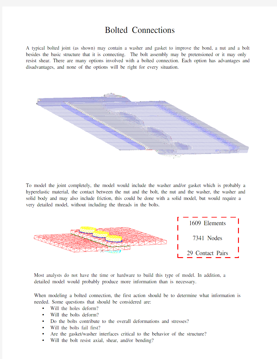
A typical bolted joint (as shown) may contain a washer and gasket to improve the bond, a nut and a bolt besides the basic structure that it is connecting. The bolt assembly may be pretensioned or it may only resist shear. There are many options involved with a bolted connection. Each option has advantages and disadvantages, and none of the options will be right for every situation.
Gasket Bolt
Nut
Washer
To model the joint completely, the model would include the washer and/or gasket which is probably a hyperelastic material, the contact between the nut and the bolt, the nut and the washer, the washer and solid body and may also include friction, this could be done with a solid model, but would require a very detailed model, without including the threads in the bolts.
1609 Elements 7341 Nodes 29 Contact Pairs
Most analysts do not have the time or hardware to build this type of model. In addition, a detailed model would probably produce more information than is necessary. When modeling a bolted connection, the first action should be to determine what information is needed. Some questions that should be considered are: ? Will the holes deform? ? Will the bolts deform? ? Do the bolts contribute to the overall deformations and stresses? ? Will the bolts fail first? ? Are the gasket/washer interfaces critical to the behavior of the structure? ? Will the bolt resist axial, shear, and/or bending?
Determining the required information would then determine the type of model that could be used. For instance, if joint forces are needed, the bolt must be modeled with an element that can recover forces.. Different element types will result in different behavior of the bolt. There are local effects that could be modeled with a break out model or submodel. Some local effects are: ? Bolts can prevent the hole from changing shape. ? The interaction of the hole and the bolt is usually a local effect. ? A sub model would be needed to find bolt failure, if the failure mode is known. ? The gasket and washers generally contribute to only localized effects. There are many modeling options. None of the options will produce exactly the behavior of the connection. The decision of which option to choose is dependent on required results and time available to produce results. Some of the modeling options include: ? Merge Nodes ? Rigid Connection ? Spring Element ? Beam Element ? Constraint Element ? Coupled DOF
This paper will discuss some of the modeling options. It is intended as an introduction to the topic and is not the final answer to modeling beam connections. The results presented were calculated using I-DEAS as the post processor and Model Solution as the solver. The paper will present some of the advantages and disadvantages of using different modeling options. It will discuss merging nodes, rigid connections (using rigid elements), spring elements and beam elements. The constraint element and coupled DOF will be left to another paper.
Merge Nodes:
Considerations: ? Connecting two bodies represented by solid elements. (Shells would not have coincident nodes) ? All forces are transferred. ? No localized behavior is considered. Concerns: ? It can be difficult to get the nodes to match. (Section meshing can help) ? No joint forces available. ? The contact between the surfaces would be very friction dependent.
There are two possible methods of merging nodes: 1. All nodes on the connecting surfaces could be merged Behavior would be the same as one body 2. Only the nodes representing the bolts could be merged
-
Contact between the surfaces should be considered
Merge Nodes – Using I-DEAS 1. Pick Nodes Select nodes to be considered For all nodes, use MB3 “All done” 2. Enter distance between nodes to be considered coincident (0.0003937008) Enter distance between nodes, the default is 1mm 3. Enter method to select coincident node Lower Number is the default 4. Ok to list element labels? (No) 5. Ok to merge coincident nodes? (No) Default is NO Select Yes to merge the nodes 6. Ok to delete nodes that have been replaced (Yes)
Rigid Elements:
Considerations: ? Selected DOF’s can be transferred. ? No localized behavior calculated. ? The hole’s shape can be maintained. Concerns: ? Joint Forces can be recovered. ? May add numeric stiffness around the hole. ? If the nodes are not coincident, a moment will be induced.
There are three possible methods using rigid elements to model the bolts.
One rigid element connecting all the nodes to one central node
Two rigid elements connected with one rigid bar
One rigid element connecting a node at the center of the hole
Rigid Elements – Using I-DEAS ? Two types of rigid elements: – RBARs - connect only 2 nodes – RBEs – connect multiple nodes – The first node is the independent node. ? Rigid elements can be created: – Manually using “create element” – Geometry-based Elements using reference points or center points ? Section meshing will automatically suppress the hole.
Recovering Joint Forces using Rigid Elements: 1. Constraint forces must be stored. They may be listed. It is recommended that element forces also be stored and listed. 2. Select constraint forces in display results. 3. Select arrow plots in display template. The forces may be listed using the report writer and similar to Arrow plot.
Spring Elements:
Considerations: ? Nodes should be coincident. ? Selected DOF can be transferred. ? Some calculations prior to the FE model would required to obtain the equivalent bolt stiffness. ? No localized behavior considered. Concerns: ? Joint Forces can be recovered. ? If nodes are not coincident a moment may be introduced. - For Ideas, it is suggested that the uniaxial flag be turned on. - For Nastran, the nodes should be coincident. ? To have no stiffness for a given DOF, set the stiffness to zero. - Ideas defaults to 3 DOF, either translational or rotational. - Nastran uses 1 DOF, multiple springs may be required to resist different forces.
There are two possible methods for modeling spring elements: 1. Connecting nodes at the center of the hole. 2. Model the hole using a rigid element and connecting the rigid elements with a spring. 3. If midsurface data is used for shell models, the spring element may induce a moment.
Spring Elements – Using I-DEAS ? Springs elements can be created: – Manually using “create element” – Geometry-based Elements using reference points or center points ? Set the solver mask before creating the physical property table entry.
Recovering Joint Forces using Spring Elements: 1. Create a group of the spring elements. 2. Store Element Forces. 3. Select Arrow Display. In Visualizer, arrows can be set to show either 1 direction or 3 directions The forces may be listed using the report writer and similar to XY graph. An XY graph must first be created.
Beam Elements:
Considerations: ? Nodes should be coincident ? Stiffness in axial, shear and bending are included based on beam section ? Forces can be transferred in selected DOF ? Localized behavior can considered ? Preload may be included Concerns: ? Joint Forces can be recovered ? A beam or a rod element can be used... - Beams model all 6 DOF - Rods model translation only ? In short beams the shear deflection will control the overall deflection of the bolt.
The beams are modeled connecting nodes at the center of the hole. The hole is not modeled, because the beam section models the bolt volume.
Beam Elements – Using I-DEAS 1. Create a beam section that represents the bolt. 2. Create beams between the center nodes of the holes. 3. The holes may be suppressed (using section meshing) OR 3. Use a rigid element to connect the edges of the hole with the beam. 4. Store Element Forces