DFL1501S中文资料
DFL15005S thru DFL1514S
Document Number 8887416-Nov-04
Vishay Semiconductors
https://www.360docs.net/doc/9e3348294.html,
1
~
~N e w P
r o d u c t
Low Profile Miniature Glass Passivated Single-Phase Surface Mount Bridge Rectifiers
Major Ratings and Characteristics
I F(AV) 1.5 A V RRM 50 V to 1400 V
I FSM 50 A I R 5 μA V F 1.1 V T j max.
150 °C
Features
?Low Profile: Typical height of 2.5 mm ?UL Recognition, file number E54214 ?Ideal for automated placement ?High surge current capability
?
Meets MSL level 1, per J-STD-020C
Typical Applications
General purpose use in ac-to-dc bridge full wave rec-tification for SMPS, Lighting Ballaster, Adapter, Bat-tery Charger, Home Appliances, Office Equipment,and Telecommunication applications
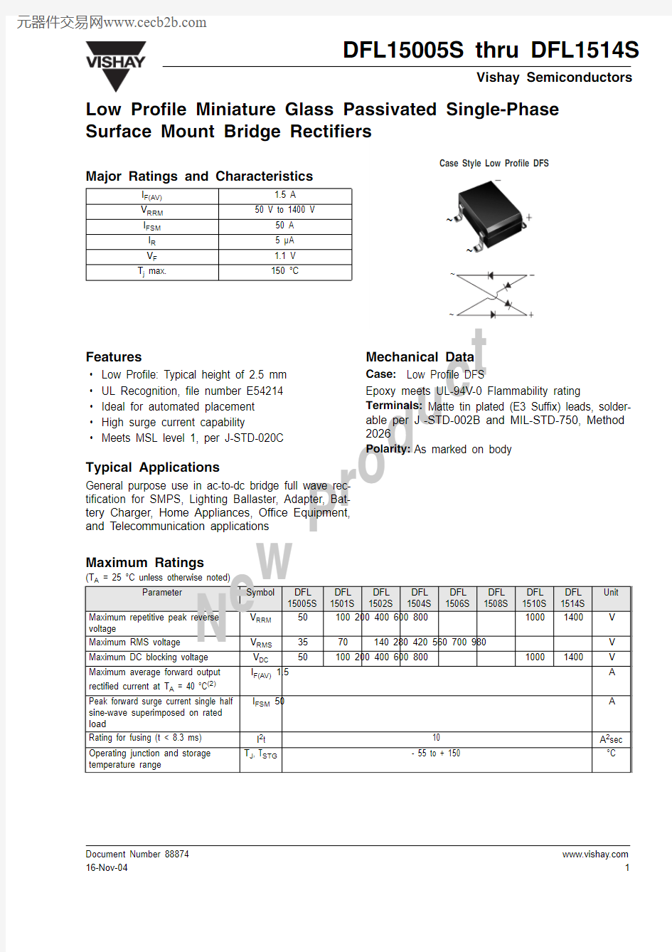
Mechanical Data
Case: Low Profile DFS
Epoxy meets UL-94V-0 Flammability rating
Terminals: Matte tin plated (E3 Suffix) leads, solder-able per J -STD-002B and MIL-STD-750, Method 2026
Polarity: As marked on body
Maximum Ratings
(T A = 25 °C unless otherwise noted)
Parameter
Symbol DFL 15005S DFL 1501S
DFL 1502S
DFL 1504S
DFL 1506S
DFL 1508S
DFL 1510S DFL 1514S
Unit
Maximum repetitive peak reverse voltage
V RRM
50 100 200 400 600 800 1000 1400 V
Maximum RMS voltage V RMS 35 70 140 280 420 560 700 980 V Maximum DC blocking voltage
V DC
50 100 200 400 600 800 1000 1400 V
Maximum average forward output rectified current at T A = 40 °C (2)
I F(AV) 1.5
A Peak forward surge current single half
sine-wave superimposed on rated load
I FSM 50 A
Rating for fusing (t < 8.3 ms) I 2t 10 A 2sec Operating junction and storage temperature range
T J , T STG
- 55 to + 150
°C
DFL15005S thru DFL1514S
Vishay Semiconductors
Electrical Characteristics
(T A = 25 °C unless otherwise noted)
Thermal Characteristics
(T A = 25 °C unless otherwise noted)
Parameter
T est condition Symbol
DFL 15005S DFL 1501S DFL 1502S DFL 1504S DFL 1506S DFL 1508S DFL 1510S DFL 1514S
Unit Max. instantaneous forward voltage drop per leg
at 1.5 A
V F 1.1 V Maximum DC reverse current at rated DC blocking voltage per leg
T A = 25 °C T A = 125 °C I R 5.0 500
μA
Typical junction capacitance per leg (1)
C J 16 pF
Parameter
Symbol DFL 15005S DFL 1501S
DFL 1502S
DFL 1504S
DFL 1506S
DFL 1508S
DFL 1510S
DFL 1514S
Unit Typical thermal resistance per leg (2) R θJA
R θJL
40 15
°C/W
DFL15005S thru DFL1514S
Document Number 8887416-Nov-04
Vishay Semiconductors
https://www.360docs.net/doc/9e3348294.html,
3
Package outline dimensions in inches (millimeters)
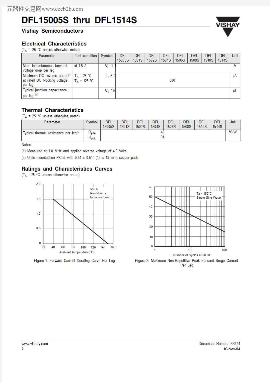
Figure 4. Typical Reverse Characteristics Per Leg