LTC3780EVM_1

QUICK START GUIDE FOR DEMONSTRATION CIRCUIT 1046A
HIGH EFFICIENCY 48V BUCK BOOST DC/DC SUPPLY
LTC3780EG/LTC4440ES6 DESCRIPTION
Demonstration circuit 1046A is a non-isolated, high
efficiency buck-boost DC/DC supply featuring LTC?3780EG and LTC?4440ES6. The LTC3780 is a high performance 4-switch synchronous buck boost
regulator and the LTC4440 is a 100V-rated FET driver. The input voltage of the demo board is de-signed for 36V to 72V. The output voltage is 48V. At 25C° room temperature, the maximum output cur-rent is 5A without a cooling fan and 6A with 150LFM air flow for cooling. An optional 12V bias flyback supply using the LTC3803 is stuffed on the board to power the LTC3780 and LTC4440.
Design files for this circuit board are available. Call the LTC factory.
, LTC and LT are registered trademarks of Linear Technology Corporation.
Table 1. Performance Summary (T A = 25°C)
PARAMETER CONDITION VALUE
Input Voltage Min / Max 36V-72V Output Voltage V OUT I OUT = 0A to 6A 48V ± 2%
VIN = 36V to 72V, no fan, at room T A=25C° 5A Maximum Output Current
VIN = 36V to 72V, 150LFM air flow, at room T A=25C° 6A Switching frequency 36V to 72V input, typical 300kHz
V IN = 36V, V OUT = 48V, I OUT = 6A 96.8% Typical
V IN = 48V, V OUT = 48V, I OUT = 6A 96.6 % Typical Full Load Efficiency
V IN = 72V, V OUT = 48V, I OUT = 6A 96.4 % Typical QUICK START PROCEDURE
Demonstration circuit 1046A is easy to set up to evaluate the performance of the LTC3780EG. Refer to Figure 1 for proper measurement equipment setup and follow the procedure below:
NOTE:When measuring the input or output voltage ripple, care must be taken to avoid a long ground lead on the oscilloscope probe. Measure the input or output voltage ripple by touching the probe tip directly across the Vin or Vout and GND terminals. See Figure 2 for proper scope probe technique.
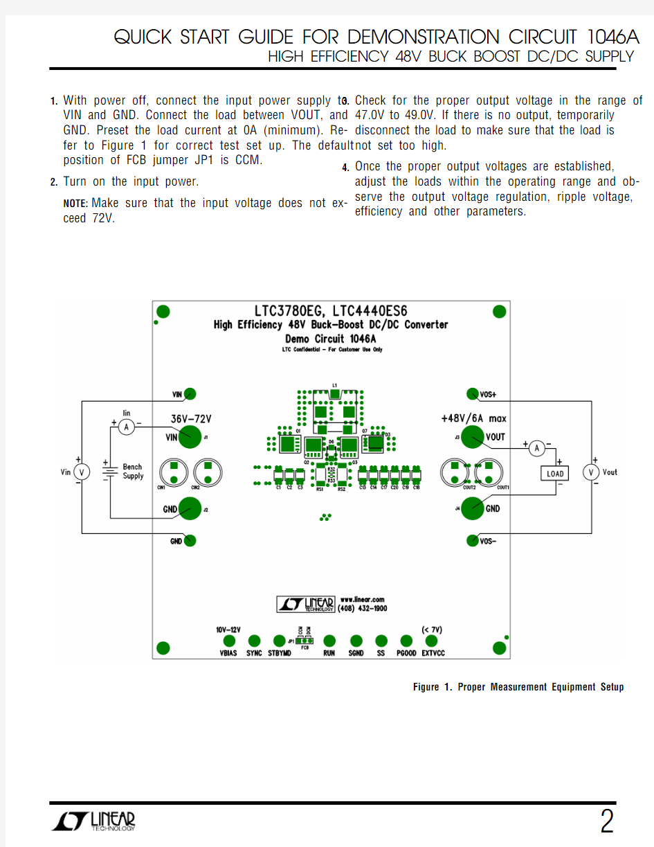
1.With power off, connect the input power supply to VIN and GND. Connect the load between VOUT, and GND. Preset the load current at 0A (minimum). Re-fer to Figure 1 for correct test set up. The default position of FCB jumper JP1 is CCM.
2.Turn on the input power.
NOTE:Make sure that the input voltage does not ex-ceed 72V. 3.Check for the proper output voltage in the range of 47.0V to 49.0V. If there is no output, temporarily disconnect the load to make sure that the load is not set too high.
4.Once the proper output voltages are established, adjust the loads within the operating range and ob-serve the output voltage regulation, ripple voltage, efficiency and other parameters.
Figure 1. Proper Measurement Equipment Setup
Figure 2. Measuring Input or Output Ripple
Figure 3. Typical Supply Efficiency vs Load Current at 36V, 48V and 72V input