D300RW中文资料
Key Features:
? 3W Output Power
? 2:1 Input Voltage Range ? 1,500 VDC Isolation ? Short Circuit Protected ? Miniature SIP Case ? Single & Dual Outputs ? 1.0 MH MTBF
? Industry Standard Pin-Out
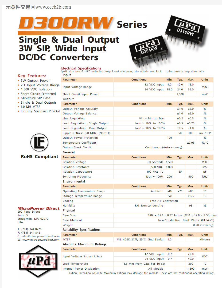
D300RW
Single & Dual Output 3W SIP , Wide Input DC/DC Con v ert e rs
Series
Input
Parameter
Conditions
Min.Typ.Max.Units Input Voltage Range 12 VDC Input 9.012.018.0VDC 24 VDC Input
18.0
24.036.0
Short Circuit Input Power
1,500
mW Output
Parameter
Conditions
Min.
Typ.Max.Units Output Voltage Accuracy ±1.0±3.0%Output Voltage Balance ±1.0
±2.0%Line Regulation
Vin = Min to Max ±0.2±0.5%Load Regulation , Single Output Iout = 10% to 100%±0.5±0.75%Load Regulation , Dual Output Iout = 10% to 100%
±0.5±1.0%Ripple & Noise (20 MHz) (Note 1)50
100mV P - P Output Power Protection 120
%Temperature Coef? cient ±0.03
%/°C
Output Short Circuit
Continuous (Autorecovery)
General
Parameter Conditions
Min.Typ.
Max.
Units Isolation Voltage 60 Seconds 1,500VDC Isolation Resistance 500 VDC 1,000
M ΩIsolation Capacitance 100 kHz, 1V 80
pF Switching Frequency
Iout = 100%
200500kHz Environmental
Parameter
Conditions
Min.Typ.Max.Units Operating Temperature Range Ambient
-40+25
+85°C Storage Temperature Range -50
+125
°C
Cooling Free Air Convection
Humidity
RH, Non-condensing
95
%
Physical
Case Size 0.87 x 0.47 x 0.37 Inches (22.0 x 12.0 x 9.50 mm)
Case Material Non-Conductive Black Plastic (UL94-V0)
Weight
0.20 Oz (6.0g)
Reliability Speci? cations
Parameter Conditions
Min.Typ.
Max.
Units MTBF
MIL HDBK 217F , 25°C, Gnd Benign
1.0MHours Absolute Maximum Ratings
Parameter
Conditions
Min.Typ.
Max.Units Input Voltage Surge (1 Sec)12 VDC Input -0.722.0VDC 24 VDC Input
-0.7
40.0Lead Temperature 1.5 mm From Case For 10 Sec
300°C Internal Power Dissipation
All Models
1,800
mW
Caution: Exceeding Absolute Maximum Ratings may damage the module. These are not continuous operating ratings.
Electrical Speci? cations
Speci? cations typical @ +25°C, nominal input voltage & rated output current, unless otherwise noted. Speci? cations subject to change without notice.
MicroPower Direct
292 Page Street
Suite D
Stoughton, MA 02072USA
T: (781) 344-8226F: (781) 344-8481
E: sales@https://www.360docs.net/doc/9f10892715.html, W: https://www.360docs.net/doc/9f10892715.html,
RoHS Compliant
Model Selection Guide
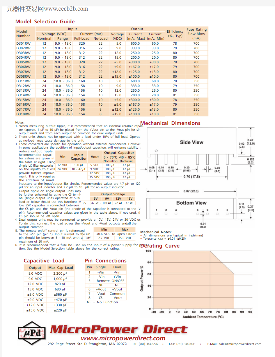
Mechanical Dimensions
Model Number Input
Output
Ef? ciency
(%, Typ)
Fuse Rating
Slow-Blow (mA)Voltage (VDC)Current (mA)Voltage (VDC)Current (mA, Max)Current
(mA, Min)Nominal Range Full-Load No-Load D301RW 129.0 - 18.032022 5.0600.060.078700D302RW 129.0 - 18.0316229.0333.033.079700D303RW 129.0 - 18.03122212.0250.025.080700D304RW 129.0 - 18.03122215.0200.020.080700D305RW 129.0 - 18.032022±5.0±300.0±30.078700D306RW 129.0 - 18.031622±9.0±167.0±17.079700D307RW 129.0 - 18.031222±12.0±125.0±13.080700D308RW 129.0 - 18.031222±15.0±100.0±10.080700D311RW 2418.0 - 36.016010 5.0600.060.078350D312RW 2418.0 - 36.0158109.0333.033.079350D313RW 2418.0 - 36.01561012.0250.025.080350D314RW 2418.0 - 36.01541015.0200.020.081350D315RW 2418.0 - 36.016010±5.0±300.0±30.078350D316RW 2418.0 - 36.015810±9.0±167.0±17.079350D317RW 2418.0 - 36.01568±12.0±125.0±13.080350D318RW
2418.0 - 36.0
1548±15.0±100.0±10.081
350
Pin Single Dual 1-Vin -Vin 2+Vin +Vin 3Remote ON/OFF 5NF NF 6+Vout +Vout 7-Vout Common 8CS -Vout NF = No Function
Pin Connections
Notes:
1. When measuring output ripple, it is recommended that an external ceramic capaci-tor (approx. 1 μF to 10 μF) be placed from the +Vout pin to the -Vout pin for single output units and from each output to common for dual output units.
2. T hese units should not be operated with a load under 10% of full load. Operation at no-load may cause damage to the unit.
3. These converters are speci? ed for operation without external components. However, in some applications the addition of input/output capacitors will enhance stability and reduce output ripple.
Recommended capaci-tor values are given in the table at right. Using
simple LC ? lter networks
on the input/output will provide further improve-ment. This only requires the addition of small
inductors to the input/output ? lter circuits. Recommended values are 4.7 μH to 120 μH for an input inductor and 2.2 μH to 10 μH for an output inductor. Output ripple on single output units may
be further enhanced by using the CS termi-nal (single output units operated at 50% load or below should use this function). A low ESR capacitor is connected between
the CS pin and the -Vout pin (the anode of the capacitor is connected to the -Vout pin). Recommended capacitor values are given in the table above. If not used, the CS pin should be left open.
4. D ual output units may be connected to provide a 10V, 18V, 24V or 30 VDC output. To do this, connect the load across the +Vout and -Vout outputs and ? oat the output common.
5. The remote on/off control pin is referenced
to the -Vin pin (pin 1). Input current to the
pin should be between 5 - 10 mA with a maximum of 20 mA.
6. It is recommended that a fuse be used on the input of a power supply for protec-
tion. See the Model Selection table above for the correct rating.
Vin Input
Capacitor
Vout Output Capacitor
0 - 70oC (Electrolitic)-40 - 85oC (Tantalum)12 VDC 100 μF 5 VDC 100 μF 47 μF 24 VDC 10 - 47 μF 9 VDC
100 μF 47 μF 12 VDC 100 μF 47 μF
15 VDC 100 μF 47 μ
F Output Voltage 5V 9V 12V 15V
CS 47 μF - 100 μF 22 μF - 47 μF Min Max On <0.6 VDC to Open Circuit Off 2.7 VDC 15.0 VDC Mechanical Notes:
? All dimensions are typical in inch e s (mm)? Tolerance x.xx = ±0.01 (±0.25)
MicroPower Direct
https://www.360docs.net/doc/9f10892715.html,
292 Page Street Ste D Stoughton, MA 02072 ? TEL: (781) 344-8226 ? FAX: (781) 344-8481 ? E-Mail: sales@https://www.360docs.net/doc/9f10892715.html,
Output Max Cap Load 5.0 VDC 2,200 μF 9.0 VDC 1,000 μF 12.0 VDC 820 μF 15.0 VDC 680 μF ±5.0 VDC ±560 μF ±9.0 VDC ±470 μF ±12.0 VDC ±330 μF ±15.0 VDC
±220 μF
Capacitive Load
Derating Curve