How_to_Estimate_Current_Drive_Strength_For_OCT

How-To Estimate Current Drive Strength for OCT
Introduction. Many Altera? FPGAs have output pin configuration options which allow you to select either a current drive strength or series on chip termination (OCT). Although these have different settings in the Quartus? II software, they use the same structures in the output buffer to implement the desired setting.
This How-To document describes how you can use IBIS models to estimate the current strength of the series OCT settings.
1. Set Up
The examples in this document use the following:
Stratix? IV device IBIS models version 2.0
HyperLynx Visual IBIS Editor Version 4.0
2. Current Drive Strength and Series OCT
The output buffers consist of pull up and pull down transistors. As you select higher drive strengths for your output and bidirectional pins in the Quartus II software, more pull up and pull down transistors are enabled in the output buffer. As the drive strength increases, the output impedance of the output buffer decreases. High current drive strength settings have a lower output impedance than low current drive strength settings.
When using series OCT, a combination of pull up and pull down transistors are enabled to provide the desired output impedance. For non-calibrated series OCT, this is a setting determined by Altera during device characterization. The non-calibrated OCT setting has a variation over process, voltage, and temperature, and this variance is provided in the respective device Datasheet. Calibrated series OCT will compare the output impedance of the output buffer with the resistance applied to the RUP and RDN pins, and dynamically enables and disables the pull up and pull down transistors until the output impedance of the buffer matches the impedance sensed on the RUP and RDN pins.
As a designer, you may want to know the approximate current drive strength when you select series OCT for output and bidirectional pins. You can use IBIS models and any IBIS viewer to generate IV curves.
3. IV Curves
The following example will show how to estimate the current drive strength of a Stratix IV device 2.5V output buffer configured for 50 ohm non-calibrated OCT located on a row I/O bank (left or right side of the device).
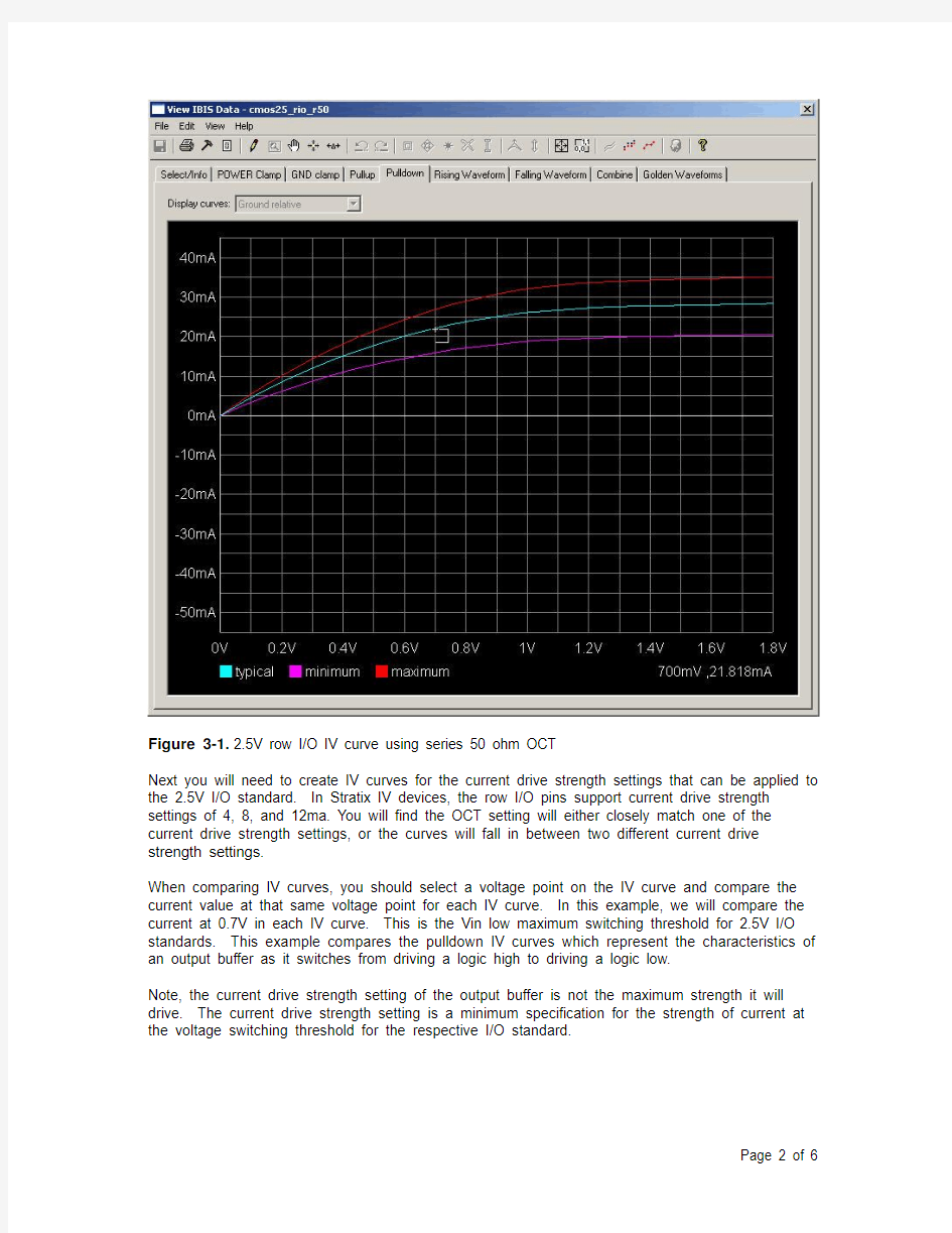
First, view the IV curve of the cmos25_rio_r50 model, this is the 50 ohm series non-calibrated OCT model for a 2.5V standard. In this example, the Pulldown curve will be used. (Note, Altera IBIS models use either “cmos” or “ttl” for I/O standards at or below 3.0V. The terms are interchangeable. See Knowledge Database Solution rd03272006_586 for further information.
Figure 3-1. 2.5V row I/O IV curve using series 50 ohm OCT
Next you will need to create IV curves for the current drive strength settings that can be applied to the 2.5V I/O standard. In Stratix IV devices, the row I/O pins support current drive strength settings of 4, 8, and 12ma. You will find the OCT setting will either closely match one of the current drive strength settings, or the curves will fall in between two different current drive strength settings.
When comparing IV curves, you should select a voltage point on the IV curve and compare the current value at that same voltage point for each IV curve. In this example, we will compare the current at 0.7V in each IV curve. This is the Vin low maximum switching threshold for 2.5V I/O standards. This example compares the pulldown IV curves which represent the characteristics of an output buffer as it switches from driving a logic high to driving a logic low.
Note, the current drive strength setting of the output buffer is not the maximum strength it will drive. The current drive strength setting is a minimum specification for the strength of current at
the voltage switching threshold for the respective I/O standard.
Figure 3-2. 2.5V row I/O IV curve using a current drive strength of 4ma
By comparing figures 3-1 and 3-2, it is easy to see the current drive strength of the 50 ohm OCT setting is higher than the 4mA setting.
T he 50 ohm OCT “typical” IV curve has 21.8mA at 0.7V, and the 4mA “typical” IV curve has
11.9mA at 0.7V.
Figure 3-3. 2.5V row I/O IV curve using a current drive strength of 8ma
By comparing figures 3-1 and 3-3, the current drive strength of the 50 ohm OCT setting is still higher than the 8mA setting.
The 50 ohm OCT “typical” IV curve has 21.8mA at 0.7V, and the 8mA “typical” IV curve has
18.1mA at 0.7V.
Figure 3-4. 2.5V row I/O IV curve using a current drive strength of 12ma
By comparing figures 3-1 and 3-4, the current drive strength of the 50 ohm OCT setting is less than the 12mA setting.
The 50 ohm OCT “typical” IV curve has 21.8mA at 0.7V, and the 12mA “typical” IV curve has 28.0mA at 0.7V.
4. Conclusion
By comparing the IV curves for each output buffer configuration using 2.5V, the current drive strength of the 50 ohm series OCT configuration is between 8mA and 12mA. When comparing the data points at the same place on the curve, the 50 ohm series OCT setting appears to be below the mid-point between the 8mA and 12mA current drive strength settings. Thus you can
estimate the current drive strength to be approximately 9 to 10mA.
5. Revision History
? 2010 Altera Corporation. All rights reserved. Altera, The Programmable Solutions Company, the stylized Altera logo, specific device designations, and all other words and logos that are identified as trademarks and/or service marks are, unless noted otherwise, the trademarks and service marks of Altera Corporation in the U.S. and other countries. All other product or service names are the property of their respective holders. Altera products are protected under numerous U.S. and foreign patents and pending applications, maskwork rights, and copyrights. Altera warrants performance of its semiconductor products to current specifications in accordance with Altera’s standard warranty, but reserves the right to make changes to any products and services at any time without notice. Altera assumes no responsibility or liability arising out of the application or use of any information, product, or service described herein except as expressly agreed to in writing by Altera. Altera customers are advised to obtain the latest version of device specifications before relying on any published information and before placing orders for products or services.