delay-locked loop
ECE658Project-Delay Locked Loop Design
Y.Sinan Hanay
December20,2007
Chapter1
Introduction
Generation and distribution of clock signals inside the VLSI systems is one of the most important problems in the design of VLSI systems.Because of the process variations and interconnect parasitics,clock signals delays vary for di erent paths.The clock signals should have zero clock skew,that is to say all the clock signals should arrive at the inputs of registers at the same time.Otherwise latches and ip- ops get clock signal at di erent time instances.In order to circuit to operate correctly these di erences should be eliminated,ideally to zero.However it is not possible practically and10%of the clock cycle is expended in order to compensate for clock skew[1].To handle this problem,several solutions are proposed.One of which is usage of H-tree clock networks,in which con guration the distance to all circuit blocks is same thus the clock delay would be same.But this technique is hard to implement since the di erent fan-out requirements for di erent blocks and routing constraints.Also some CAD techniques and heuristics are used in the routing of the clock trees[6].
The reduction of clock skew is one of the important problems in the VLSI design.Passive techniques such as clock network optimization techniques cannot completely reduce the clock skew[2].Phase-locked loops and delay-locked loops(DLL)are extensively used in VLSI circuits in order to decrease clock screw in the clock networks.DLL is a rst order loop that compares it`s input with a reference signal,than delay it`s output so that it can synchronize with the reference signal in a feedback fashion.
DLL consists of4units:
1.Phase Detector
2.Charge Pump
3.Filter
4.Voltage Controlled Delay Line(VCDL)
It`s working principle is as follows:First,phase detect block compares the reference clock signal with the output signal,depending on the di erence,if reference signal is leading the output Up(U)signal,else if the reference signal lagging the output signal Down(D)signal is asserted,and thus controls the delay line appropriately.VCDL adjusts the phase of the output signal proportional to the di erence between reference signal until the output signal is high%50
of the time.In the gure below this principle is illustrated
DLL Design
DLLs are notoriously di cult to build correctly.They require expertise in both feedback control systems and analog design.
(N.Weste,D.Harris,A.Banerjee,2005:490[14])
In this project some part of the design required Analog design and control systems background. DLLs can be classi ed in two groups:Analog and Digital DLLs.Digital DLLs have the advantage of higher exibility on supply voltage and low design complexity,while Analog DLLs o er better jitter[9],smaller area,low noise sensitivity and power consumption[8].The DLL consists of four main components,and they will be discussed in the following sections.
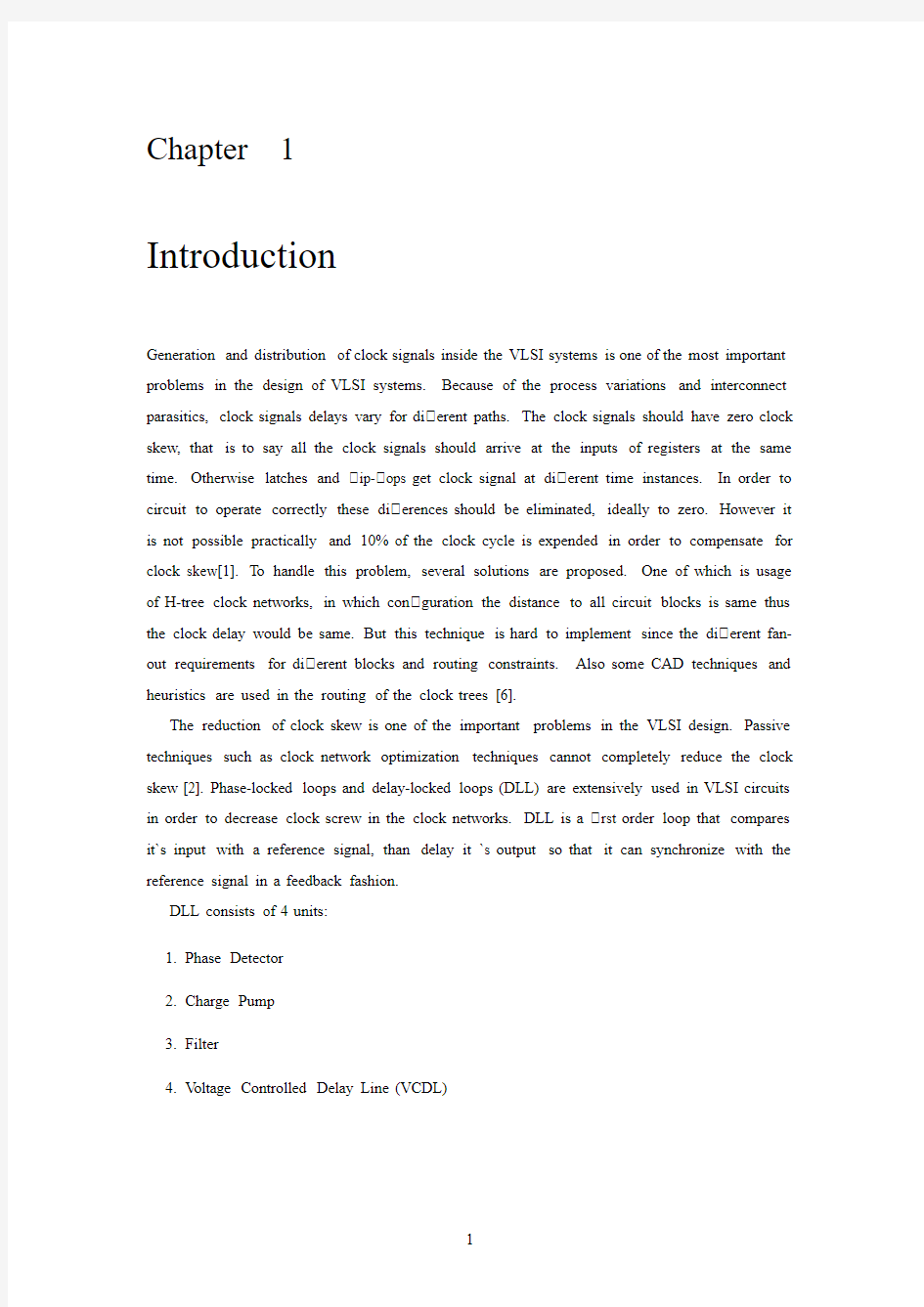
1.1Phase Detector
In order to deskew the clock, rst of all the skew must be known.This skew can be detected by the phase detectors.Its function is to detect the phase di erence between reference clock signal with the input clock signal.It takes these clock signals as input and produces an output that is proportional to the phase di erence.Phase detectors can be analog or digital.The rst phase detectors used in locked-loops was the linear multiplier phase detector,but as the PLLs became to implemented by digital components,digital phase detectors become popular[7].Simplest digital detector is an XOR gate,of which output is zero if the two inputs have same phase, and one as long as they are not equal.Phase detectors can be implemented digitally by J-K ip- ops.In this work,linear phase detector proposed in[4]is implemented is shown in Figure 1.1.Schematic and layout of the phase detector are shown in Figure1.2and1.3.
Figure1.2:Phase Detector
Figure1.3:Layout of the Phase Detector
1.2Charge Pump
Charge pump design was one of the most complicated part of the DLL.The zero-o set charge pump that was mentioned in[5]was used.Figures1.4and1.5shows the schematic and layout of the charge pump.
1.3Filter
Figure1.4:Schematic of the Charge Pump
eleminating the higher frequency terms(odd-harmonics)in the product.This elemination,or ltering,is done by a low pass lter.In DLLs there is no need to include a low pass lter, instead a capacitor is used in order to integrate the phase error mainly,and thus increasing control voltage appropriately.So lter block is simply a capacitor,and a100fF capacitor was used.Increasing capacitor increases the lock time while decreases the bandwidth and the ripples on the control voltage,and decreasing it decreases lock time and increases the ripples.
1.4Voltage Controlled Delay Line
The function of Voltage Controlled Delay Line(VCDL)is to delay the reference signal so that there is no skew between the output clock and reference signal.Its transfer function is simply, t d=κDL V filter
where V filter is the ltered control input to the VCDL fromcharge pump,t d is the delay(the output)andκis the gain of VCDL.The minimum and maximum delay should be T c
and1.5×T c
2 For the voltage controlled line,there are several di erent techniques can be employed by analog or digital circuitry.The most common techniques use cascaded inverters.Inverters are used speci cally for the highest delay resolution.Two main usage of cascaded inverters are called: 1)Current-Starved Inverter Delay Line(in Figure1.6)and2)Shunt Capacitor Delay Stage(or Capacitor-Loaded Inverter Delay Line in Figure1.7[10].
The delay range of Current-starved inverter circuit is higher than Shunt-capacitor circuit, however Shunt-capacitor transfer function is more linear and has lower gain than the that of Current-starved one[11,10].Lower gain is important because higher gain also ampli es the
Figure1.5:Layout of the Charge Pump
the VCDL is modeled as linear with gainκdl.In this project I used a two-stage shunt-capacitor delay circuit for the reasons mentioned above.The reason for using two stage is because its noise immunity is higher.Increasing delay stages increasesκd,and which in turn will increase the jitter[13].I also implemented8stage VCDL but did not get satisfactory results.Figure1.8 shows the implemented VCDL`s transfer characteristics.Maximum achievable delay is around
1.4ns.
Figure1.6:Current-Starved Inverter Delay Line[10]
Figure1.7:Shunt Capacitor Delay Stage[12]
Figure1.8:Implemented VCDL`s Transfer Characteristics
1.5Simulations
Figure1.11shows the simulation results for250MHz.As it can be seen from the gure,the locking is achieved aroung14th cycle with a static phase error of194ps when the clock is leading the reference signal.By decreasing charge pump`s output resistance it is possible to delay in a shorter time and suppressing the phase error.The results of decreasing charge pump`s output resistance is show in Figure1.12.It reveals that locking is achieved at6th clock cycle,but drawback here is the pulse-width of the clock is decreased too.Figures also show that in the lock state,both UP and DOWN signals are asserted for same duration,and the charge pump current rst increases then decreases by the same amount,e ectively putting no net charge to lter.Figure1.13shows the static error of192ps for DLL running at1GHz,when the clock is lagging the reference signal.
Figure1.9:Layout of the VCDL
Figure1.10:Layout of the DLL
Figure1.11:DLL at250MHz
Figure1.12:DLL at250MHz
Figure1.13:DLL at1GHz
Results and Conclusions
In this section implemented DLL`s performance is compared with some previous works.
This Work JSSC99[9]Thesis[8]
Process0.25μm CMOS0.40μm CMOS0.18μm CMOS Max Operating Frequency800MHz667MHz700MHz
Min Operating Frequency200MHz250MHz160MHz
Lock Time14cycles 2.9μs11cycles Static Phase Error192ps 80ps The DLL`s noise immunity can be improved by employing Self Biased techniques mentioned in which the process dependent variables in the system dynamics are eliminated[5].In another work,noise immunity is increased by using regulated Supply CMOS Bu ers[4].However since these techniques require di erential elements it increases the circuit complexity
Appendix
L VS Reports
1)L VS Report of the Phase Detector
@(#)$CDS:LVS version5.0.006/02/200321:50(cds11620)$
Like matching is https://www.360docs.net/doc/a91609595.html, swapping is https://www.360docs.net/doc/a91609595.html,ing terminal names as correspondence https://www.360docs.net/doc/a91609595.html,piling Diva LVS rules...
Net-list summary for/grads/h/hanay/Dokuman/proje/LVS/layout/netlist count18nets6 terminals14pmos16nmos
Net-list summary for/grads/h/hanay/Dokuman/proje/LVS/schematic/netlist count18nets 6terminals14pmos16nmos
Terminal correspondence points1DN2UP3ckin4ckref5gnd!6vdd!
The net-lists match.
instances layout schematic
un-matched00
rewired00
size errors00
pruned00
active3030
total3030
nets un-matched00merged00pruned00active1818total1818
terminals un-matched00matched but di erent type00total66
Probe les from/grads/h/hanay/Dokuman/proje/LVS/schematic
devbad.out:
netbad.out:
mergenet.out:
termbad.out:
prunenet.out:
prunedev.out:
audit.out:
prunenet.out:
prunedev.out:
audit.out:
2)L VS Report of the Charge Pump
@(#)$CDS:LVS version5.0.006/02/200321:50(cds11620)$
Like matching is https://www.360docs.net/doc/a91609595.html, swapping is https://www.360docs.net/doc/a91609595.html,ing terminal names as correspondence https://www.360docs.net/doc/a91609595.html,piling Diva LVS rules...
Net-list summary for/grads/h/hanay/LVS/layout/netlist
count
13nets
6terminals
10pmos
8nmos
Net-list summary for/grads/h/hanay/LVS/schematic/netlist
count
13nets
6terminals
10pmos
8nmos
Terminal correspondence points1DN2OUT3UP4VBN5gnd!6vdd!
The net-lists match.
instances layout schematic
un-matched00
rewired00
size errors00
pruned00
active1818
total1818
nets un-matched00merged00pruned00active1313total1313
terminals un-matched00matched but di erent type00total66
Probe les from/grads/h/hanay/LVS/schematic
devbad.out:
netbad.out:
Probe les from/grads/h/hanay/LVS/layout
devbad.out:
netbad.out:
mergenet.out:
termbad.out:
prunenet.out:
prunedev.out:
audit.out:
2)L VS Report of the Voltage Controlled Delay Line
@(#)$CDS:LVS version5.0.006/02/200321:50(cds11620)$
Like matching is https://www.360docs.net/doc/a91609595.html, swapping is https://www.360docs.net/doc/a91609595.html,ing terminal names as correspondence https://www.360docs.net/doc/a91609595.html,piling Diva LVS rules...
Net-list summary for/grads/h/hanay/LVS/layout/netlist count8nets5terminals2pmos 14nmos
Net-list summary for/grads/h/hanay/LVS/schematic/netlist count8nets5terminals2pmos 6nmos
Terminal correspondence points1gnd!2out3vctrl4vdd!5vin
The net-lists match.
instances layout schematic
un-matched00
rewired00
size errors00
pruned00
active168
total168
nets un-matched00merged00pruned00active88total88
terminals un-matched00matched but di erent type00total55
Probe les from/grads/h/hanay/LVS/schematic
devbad.out:
netbad.out:
mergenet.out:
termbad.out:
prunenet.out:
Probe les from/grads/h/hanay/LVS/layout devbad.out:
netbad.out:
mergenet.out:
termbad.out:
prunenet.out:
prunedev.out:
audit.out:
Bibliography
[1]S.M.Kang,Y.Leblebici,CMOS Digital Integrated Circuits,McGraw Hill,2003.
[2]Z.Zilic,Phase-and Delay-Locked Loop Clock Control in Digital Systems,
https://www.360docs.net/doc/a91609595.html,.
[3]J.M.Rabaey,A.Chandrakasan,and B.Nikolic,Digital Integrated Circuits,2nd ed.,Prentice
Hall,2003.
[4]S.Sidiropoulos,D.Liu,J.Kim,G.Wei,and M.Horowitz.Adaptive bandwidth DLLs and
PLLs using regulated supply CMOS bu ers.In Proc.IEEE Symposium on VLSI Circuits, pages124 127,June2000.
[5]Maneatis,et al.,"Low-Jitter Process-Independent DLL and PLL Based on Self-Biased Tech-
niques,"IEEE Journal of Solid-State Circuits,Vol.31,No.11,November1996.
[6]N.Menezes,S.Pullela,A.Balivada and L.T.Pillage,Skew Reduction in Clock Trees Using
Wire Width Optimization,Proceedings Custom Integrated Circuits Conference,May1993.
[7]R.E.Best,Phase-Locked Loops,6th Edition,McGraw Hill,2007.
[8]C.Jia,A Delay-Locked Loop for Multiple Clock Phases/Delays Generation,Doctoral Thesis,
Georgia Institute of Technology,2005.
[9]B.W.Garlepp,K.S.Donnelly,J.Kim,P.S.Chau,J.L.Zerbe,C.Huang,C.V.Tran,C.
L.Portmann,D.Stark,Y.-F.Chan,T.H.Leen,and M.A.Horowitz, A Portable Digital DLL for High-Speed CMOS Interface Circuits, IEEE J.Solid-State Circuits,vol.34,pp.
632 644,May1999.
[10]M.G.Johnson and M.E.Hudson, A variable delay line PLL for CPUcoprocessor synchro-
nization, IEEE J.Solid-State Circuits,vol.23,pp.1218 1223,Oct.1988.
[11]W.J.Dally and J.W.Poulton, Digital Systems Engineering ,Cambridge University Press,
1998.
[12]S.Liu,J.Lee and H.Tsao,"Low-power clock-deskew bu er for high-speed digital circuits",
IEEE Journal of Solid-State Circuits,SC-34,pp.554-558,April1999.
[14]N.H.E.Weste,D.Harris and A.Banerjee, CMOS VLSI Design A Circuits and Systems
Perspective ,Pearson Addison-Wesley,2005.
[15]B.Razavi, Design of CMOS Analog Integrated Circuits ,McGraw Hill,2001.
[16]P.Gray,P.J.Hurst,S.H.Lewis,R.G.Meyer, Analysis and Design of Analog Integrated
Circuits ,John Wiley Sons,Inc,2001.
51单片机汇编指令集(附记忆方法)
51单片机汇编指令集 一、数据传送类指令(7种助记符) MOV(英文为Move):对内部数据寄存器RAM和特殊功能寄存器SFR的数据进行传送; MOVC(Move Code)读取程序存储器数据表格的数据传送; MOVX (Move External RAM) 对外部RAM的数据传送; XCH (Exchange) 字节交换; XCHD (Exchange low-order Digit) 低半字节交换; PUSH (Push onto Stack) 入栈; POP (Pop from Stack) 出栈; 二、算术运算类指令(8种助记符) ADD(Addition) 加法; ADDC(Add with Carry) 带进位加法; SUBB(Subtract with Borrow) 带借位减法; DA(Decimal Adjust) 十进制调整; INC(Increment) 加1; DEC(Decrement) 减1; MUL(Multiplication、Multiply) 乘法; DIV(Division、Divide) 除法; 三、逻辑运算类指令(10种助记符) ANL(AND Logic) 逻辑与; ORL(OR Logic) 逻辑或; XRL(Exclusive-OR Logic) 逻辑异或; CLR(Clear) 清零; CPL(Complement) 取反; RL(Rotate left) 循环左移; RLC(Rotate Left throught the Carry flag) 带进位循环左移; RR(Rotate Right) 循环右移; RRC (Rotate Right throught the Carry flag) 带进位循环右移; SWAP (Swap) 低4位与高4位交换; 四、控制转移类指令(17种助记符) ACALL(Absolute subroutine Call)子程序绝对调用; LCALL(Long subroutine Call)子程序长调用; RET(Return from subroutine)子程序返回; RETI(Return from Interruption)中断返回; SJMP(Short Jump)短转移; AJMP(Absolute Jump)绝对转移; LJMP(Long Jump)长转移; CJNE (Compare Jump if Not Equal)比较不相等则转移;
dowhile循环教学设计
《Do/while条件循环语句》教学设计 教学对象:高一课时:1学时执教教师:信息技术教研组金子芬一、设计思想 本课主要采用多元智能理论得技术融入生活得教学宗旨,以任务驱动、讲练结合得教学模式,多角度应用循环思想解决实际问题,以求高效编程;多元化学习体验,以flash展现实验过程应用循环语句,以信息技术网站形式进行在线测试式进行学情调查与课堂反馈;应用比较、观察等多维求知方法深入理解程序执行过程与编程语法规则. 二、教材分析 1.教材内容:所属高一年级必修内容《信息技术基础》第三章信息得加工中得3、4算法及其实现之语句——条件do/while循环。采用vb语言编程,共 1学时40分钟。 2.教材地位: ⑴循环就是设计与实现较为复杂算法得基础。本课在学习for循环基础上理解do循环; ⑵学会do语句基本格式与表示方法,理解执行要求与应用环境。实现for与do转换。 三、学情分析 1。学生在学会for循环语句得基础上理解do循环语句,应更注重实际问题得应用. 2.避免“轻算法、重程序”,应利用流程图在熟悉书写规则得基础上设置循环条件,应注重算法与程序得结合。从专业化角度强调语句书写与表达得规范性。 四、教学目标 (一)知识与技能 1、掌握do/while循环语句得基本格式、功能与执行流程;; 2、结合流程图学会使用do/while循环语句解决实际问题,学会调试运行。 (二)方法与过程 通过实例引导与任务驱动得方式,多角度应用循环思想解决实际问题、多元化学习体验、多维求知方法以信息技术在线测试等手段巩固理论知识,反馈课堂效果. (三)情感态度与价值 1、培养学生分析、解决问题得能力,将编程思想融入生活,解决生活实际问题; 2、强化对技术与理论知识规范表达,提高专业化技能,提高信息素养。 五、重点难点
51单片机指令表汇总
51单片机指令表 助记符指令说明字节数周期数 (数据传递类指令) MOV A,Rn 寄存器内容传送到累加器 1 1 MOV A,direct 直接地址内容传送到累加器 2 1 MOV A,@Ri 间接RAM内容传送到累加器 1 1 MOV A,#data 立即数传送到累加器 2 1 MOV Rn,A 累加器内容传送到寄存器 1 1 MOV Rn,direct 直接地址内容传送到寄存器 2 2 MOV Rn,#data 立即数传送到寄存器 2 1 MOV direct,Rn 寄存器内容传送到直接地址 2 2 MOV direct,direct 直接地址传内容传送到直接地址 3 2 MOV direct,A 累加器内容传送到直接地址 2 1 MOV direct,@Ri 间接RAM内容传送到直接地址 2 2 MOV direct,#data 立即数传送到直接地址 3 2 MOV @Ri,A 累加器内容传送到间接RAM 1 1 MOV @Ri,direct 直接地址内容传送到间接RAM 2 2 MOV @Ri,#data 立即数传送到间接RAM 2 1 MOV DPTR,#data16 16 位地址传送到数据指针 3 2 MOVC A,@A+DPTR 代码字节传送到累加器 1 2 MOVC A,@A+PC 代码字节传送到累加器 1 2 MOVX A,@Ri 外部RAM(8位地址)内容传送到累加器 1 2 MOVX A,@DPTR 外部RAM(16位地址)内容传送到累加器 1 2 MOVX @Ri,A 累加器内容传送到外部RAM(8位地址) 1 2 MOVX @DPTR,A 累加器内容传送到外部RAM(16 地址) 1 2 PUSH direct 直接地址内容压入堆栈 2 2 POP direct 堆栈内容弹出到直接地址 2 2 XCH A,Rn 寄存器和累加器交换 1 1 XCH A, direct 直接地址和累加器交换 2 1
循环结构(While_Do循环)
四. While循环 1.While循环的格式: While <条件表达式> 循环体 Wend 说明:<条件表达式>为关系或逻辑表达式。 2.执行过程:判断条件;条件满足,执行循环体语句;再继续判断条件,继续执行循环; 直到条件不满足,结束循环。 结合下面我们熟悉的For程序,来说明: For I = 1 To 10 S = S + I Next I Print I 改用While循环表示: I = 1 ‘初值 While I<=10 ‘循环条件 S=S+I I=I+1 ‘变量自增,加步长 Wend Print S 3.While循环的说明 For循环语句必须给出初值、终值、步长值;循环条件也就给出了。 While循环语句中只给出循环条件和终值,所以一定要注意给出初值和增量。如上面程序段中的3处颜色部分语句。 例如:以下程序段循环几次,y值结果如何。 y = 2 While y < = 8 y = y + y Wend Print y 分析: 循环条件:y<=8 执行过程如下: Y=2,y<=8 满足,执行语句:y = y + y,y=4;遇到Wend返回继续判断条件。 Y=4,y<=8 满足,执行语句:y = y + y,y=8;遇到Wend返回继续判断条件。 Y=8,y<=8 满足,执行语句:y = y + y ,y=16;遇到Wend返回继续判断条件。 Y=16,y<=8 不满足,结束循环。 循环执行了3次。
五.Do循环 Do循环是在While循环基础上做了一点修改。整个格式结构和执行过程基本一样。 但增加了一种格式:条件不满足就循环,满足就结束循环。 格式1:Do While (条件) 循环体 Loop I=1 Do While I<4 S=S+1 I=I+1 Loop Print S I=1 Do Until I>=40 S=S+1 I=I+1 Loop 格式2:Do 循环体 Loop While (条件) 说明:格式1、格式2和While基本一样,格式2不同在于先执行一次循环,再判断条件是否满足。 格式3:Do Until(条件) 循环体 Loop 格式4:Do 循环体 Loop Until(条件) 说明:Until和While的不同在于条件不满足才循环。 注意:为了避免循环条件的混淆,我们一般是将Until 循环转换为While 循环做题。即将Until改为While,后面的条件改取相反值条件。
(完整版)51单片机汇编指令(全)
指令中常用符号说明 Rn当前寄存器区的8个工作寄存器R0~R7(n=0~7) Ri当前寄存器区可作为地址寄存器的2个工作寄存器R0和R1(i=0,1) Direct8位内部数据寄存器单元的地址及特殊功能寄存器的地址 #data表示8位常数(立即数) #data16表示16位常数 Add16表示16位地址 Addr11表示11位地址 Rel8位代符号的地址偏移量 Bit表示位地址 @间接寻址寄存器或基址寄存器的前缀 ( )表示括号中单元的内容 (( ))表示间接寻址的内容 指令系统 数据传送指令(8个助记符) 助记符中英文注释 MOV Move 移动 MOV A , Rn;Rn→A,寄存器Rn的内容送到累加器A MOV A , Direct;(direct)→A,直接地址的内容送A MOV A ,@ Ri;(Ri)→A,RI间址的内容送A MOV A , #data;data→A,立即数送A MOV Rn , A;A→Rn,累加器A的内容送寄存器Rn MOV Rn ,direct;(direct)→Rn,直接地址中的内容送Rn MOV Rn , #data;data→Rn,立即数送Rn MOV direct , A;A→(direct),累加器A中的内容送直接地址中 MOV direct , Rn;(Rn)→direct,寄存器的内容送到直接地址 MOV direct , direct;(direct)→direct,直接地址的内容送到直接地址 MOV direct , @Ri;((Ri))→direct,间址的内容送到直接地址 MOV direct , #data;8位立即数送到直接地址中 MOV @Ri , A;(A)→@Ri,累加器的内容送到间址中 MOV @Ri , direct;direct→@Ri,直接地址中的内容送到间址中 MOV @Ri , #data; data→@Ri ,8位立即数送到间址中 MOV DPTR , #data16;data16→DPTR,16位常数送入数据指针寄存器,高8位送入DPH,低8位送入DPL中(单片机中唯一一条16位数据传送指令) (MOV类指令共16条)
C51单片机指令集大全
格式功能简述字节数周期 一、数据传送类指令 MOV A, Rn 寄存器送累加器 1 1 MOV Rn,A 累加器送寄存器 1 1 MOV A ,@Ri 内部RAM单元送累加器 1 1 MOV @Ri ,A 累加器送内部RAM单元 1 1 MOV A ,#data 立即数送累加器 2 1 MOV A ,direct 直接寻址单元送累加器 2 1 MOV direct ,A 累加器送直接寻址单元 2 1 MOV Rn,#data 立即数送寄存器 2 1 MOV direct ,#data 立即数送直接寻址单元 3 2 MOV @Ri ,#data 立即数送内部RAM单元 2 1 MOV direct ,Rn 寄存器送直接寻址单元 2 2 MOV Rn ,direct 直接寻址单元送寄存器 2 2 MOV direct ,@Ri 内部RAM单元送直接寻址单元 2 2 MOV @Ri ,direct 直接寻址单元送内部RAM单元 2 2 MOV direct2,direct1 直接寻址单元送直接寻址单元 3 2 MOV DPTR ,#data16 16位立即数送数据指针 3 2 MOVX A ,@Ri 外部RAM单元送累加器(8位地址) 1 2 MOVX @Ri ,A 累加器送外部RAM单元(8位地址) 1 2 MOVX A ,@DPTR 外部RAM单元送累加器(16位地址) 1 2 MOVX @DPTR ,A 累加器送外部RAM单元(16位地址) 1 2 MOVC A ,@A+DPTR 查表数据送累加器(DPTR为基址) 1 2 MOVC A ,@A+PC 查表数据送累加器(PC为基址) 1 2 XCH A ,Rn 累加器与寄存器交换 1 1 XCH A ,@Ri 累加器与内部RAM单元交换 1 1 XCHD A ,direct 累加器与直接寻址单元交换 2 1 XCHD A ,@Ri 累加器与内部RAM单元低4位交换 1 1 SWAP A 累加器高4位与低4位交换 1 1 POP direct 栈顶弹出指令直接寻址单元 2 2 PUSH direct 直接寻址单元压入栈顶 2 2 二、算术运算类指令 ADD A, Rn 累加器加寄存器 1 1 ADD A,@Ri 累加器加内部RAM单元 1 1 ADD A, direct 累加器加直接寻址单元 2 1 ADD A, #data 累加器加立即数 2 1 ADDC A, Rn 累加器加寄存器和进位标志 1 1 ADDC A,@Ri 累加器加内部RAM单元和进位标志 1 1 ADDC A, #data 累加器加立即数和进位标志 2 1 ADDC A, direct 累加器加直接寻址单元和进位标志 2 1 INC A 累加器加1 1 1 INC Rn 寄存器加1 1 1
While循环和dowhile循环
while循环和do while循环 教学目标:①熟记while 与do while 的语法; ②领会while 与do while 的执行过程; ③分清while 与do while 的区别。 水平目标:会使用while与do while 解决实际问题 重点: ② ③ 难点:③ 教学方法:讲练结合法、自学指导法、操作演示法 教学过程: 前提测评: 1、循环的种类有哪些? 2、用for循环求1到100之间所有偶数之和? 导入新课: 新课讲授: 一、While 循环 一般形式: While(表达式) { 语句; } 流程图:
例:main() { int i; i=0; while(i<=10) { Printf(“i=%d\n”,i); i++; } getch(); } 注: ①循环体如果包含一个以上的语句,应该用花括弧括起来,以复合语句形式出现,如果 不加花括弧,则while语句的范围只到while后面第一个分号处。 ②在循环体中,应有使循环趋向结束的语句。 ③循环变量初始化的操作应在while语句之前完成。 练:用while 循环求1到100之间所有偶数之和。 参考答案: #include stdio.h Main() { int i,sum; clrscr(); i=0; sum=0; while(i<=100) { if (i%2==0) sum=sum+i; i++; } printf(“sum=%d”,sum); getch(); } 二、do while 循环(自学) 要求:1、记住do while 循环的语法 2、会依流程图解释do while 的执行过程 一般形式:题:以下do while语句准确的是()。 do (A) do (B)do { sum+=i { sum+=i; 语句;i++ i++; }while(i<10) }while(表达式);(C) do (D) do sum+=i; { i++; sum+=i; While(i<10); i++;
常用51单片机汇编指令
常用单片机汇编指令: 1 .MOV A,Rn寄存器内容送入累加器 2 .MOV A,direct 直接地址单元中的数据送入累加器 3 .MOV A,@Ri (i=0,1) 间接RAM中的数据送入累加器 4 .MOV A,#data 立即数送入累加器 5 .MOV Rn,A累加器内容送入寄存器 6 .MOV Rn,direct 直接地址单元中的数据送入寄存器 7 .MOV Rn,#data 立即数送入寄存器 8 .MOV direct,A 累加器内容送入直接地址单元 9 .MOV direct,Rn 寄存器内容送入直接地址单元 10. MOV direct,direct 直接地址单元中的数据送入另一个 直接地址单元 11 .MOV direct,@Ri (i=0,1) 间接RAM中的数据送入直接地址单元 12 MOV direct,#data 立即数送入直接地址单元 13 .MOV @Ri,A (i=0,1) 累加器内容送间接RAM单元 14 .MOV@Ri,direct (i=0,1)直接地址单元数据送入间接RAM 单元 15 .MOV @Ri,#data (i=0,1) 立即数送入间接RAM单元 16 .MOV DPTR,#data16 16 位立即数送入地址寄存器 17 .MOVC A,@A+DPTR以DPTR^基地址变址寻址单元中的数 据送入累加器
18 .MOVC A,@A+PC以PC为基地址变址寻址单元中的数据送入累加器 19 .MOVX A,@Ri (i=0,1) 外部RAM(8位地址)送入累加器 20 .MOVX A,@DPTR外部RAM(16位地址)送入累加器 21 .MOVX @Ri,A (i=0,1) 累计器送外部RAM(8位地址) 22 .MOVX @DPTR,A累计器送外部RAM( 16位地址) 23 .PUSH direct 直接地址单元中的数据压入堆栈 24 .POP direct 弹栈送直接地址单元 25 .XCH A,Rn 寄存器与累加器交换 26 .XCH A,direct 直接地址单元与累加器交换 27 .XCH A,@Ri (i=0,1) 间接RAM与累加器交换 28 .XCHD A,@Ri (i=0,1) 间接RAM的低半字节与累加器交换算术操作类指令: 1. ADD A,Rn 寄存器内容加到累加器 2 .ADD A,direct 直接地址单元的内容加到累加器 3 A.DD A,@Ri (i=0,1) 间接ROM的内容加到累加器 4 .ADD A,#data 立即数加到累加器 5 .ADDC A,Rn寄存器内容带进位加到累加器 6 .ADDC A,direct 直接地址单元的内容带进位加到累加器 7 .ADDC A,@Ri(i=0,1) 间接ROM的内容带进位加到累加器 8 .ADDC A,#data 立即数带进位加到累加器
51单片机指令表
此表主要是为了方便大家查阅每条指令的作用,写法以及字节数和周期数,建议大家保存为书签。 助记符指令说明字节数周期数 (数据传递类指令) MOV A,Rn 寄存器传送到累加器 1 1 MOV A,direct 直接地址传送到累加器 2 1 MOV A,@Ri 累加器传送到外部RAM(8 地址) 1 1 MOV A,#data 立即数传送到累加器 2 1 MOV Rn,A 累加器传送到寄存器 1 1 MOV Rn,direct 直接地址传送到寄存器 2 2 MOV Rn,#data 累加器传送到直接地址 2 1 MOV direct,Rn 寄存器传送到直接地址 2 1 MOV direct,direct 直接地址传送到直接地址 3 2 MOV direct,A 累加器传送到直接地址 2 1 MOV direct,@Ri 间接RAM 传送到直接地址 2 2 MOV direct,#data 立即数传送到直接地址 3 2 MOV @Ri,A 直接地址传送到直接地址 1 2 MOV @Ri,direct 直接地址传送到间接RAM 2 1 MOV @Ri,#data 立即数传送到间接RAM 2 2 MOV DPTR,#data16 16 位常数加载到数据指针 3 1 MOVC A,@A+DPTR 代码字节传送到累加器 1 2 MOVC A,@A+PC 代码字节传送到累加器 1 2 MOVX A,@Ri 外部RAM(8 地址)传送到累加器 1 2 MOVX A,@DPTR 外部RAM(16 地址)传送到累加器 1 2 MOVX @Ri,A 累加器传送到外部RAM(8 地址) 1 2 MOVX @DPTR,A 累加器传送到外部RAM(16 地址) 1 2 PUSH direct 直接地址压入堆栈 2 2 POP direct 直接地址弹出堆栈 2 2 XCH A,Rn 寄存器和累加器交换 1 1
MCS51单片机指令大全
MCS-51系列单片机指令大全 以字母的顺序排列(A--Z) A: -------------------------------------------------------------------- 1、ACALL addr11 指令名称:绝对调用指令 指令代码: A10 A9 A9 1 0 0 0 1 A7 A6 A5 A4 A3 A2 A1 A0 指令功能:构造目的地址,进行子程序调用其方法是以指令提供的11位地址(al0~a0),取代PC的低11位,PC的高5位不变。 操作内容: PC←(PC)+2 SP←(SP)+1 (SP)←(PC)7~0 SP←(SP)+1 (SP)←(PC)15~8 PC10~0←addr l0~0 字节数: 2 机器周期:2 使用说明:由于指令只给出子程序入口地址的低11位,因此调用范围是2KB。 2、ADD A,Rn
指令代码:28H~2FH 指令功能:累加器内容与寄存器内容相加 操作内容:A←(A)+(R n), n=0~7 字节数: 1 机器周期;1 影响标志位:C,AC,OV 3、ADD A,direct 指令名称:直接寻址加法指令 指令代码:25H 指令功能:累加器内容与内部RAM单元或专用寄存器内容相加操作内容:A←(A)+(direct) 字节数: 2 机器周期:1 影响标志位:C,AC,OV 4、ADD A,@Ri 指令名称:间接寻址加法指令 指令代码:26H~27H 指令功能:累加器内容与内部RAM低128单元内容相加 操作内容:A←(A)+((Ri)), i=0,1 字节数: 1 机器周期:1 影响标志位:C,AC,OV 5、ADD A,#data
MCS-51单片机汇编指令详解
MCS-51单片机汇编指令详解 以累加器为目的操作数的指令 MOV A,Rn MOV A,direct MOV A,@Ri MOV A,#data 第一条指令中,Rn代表的是R0-R7。第二条指令中,direct 就是指的直接地址,而第三条指令中,就是我们刚才讲过的。第四条指令是将立即数data送到A中。 下面我们通过一些例子加以说明: MOV A,R1 ;将工作寄存器R1中的值送入A,R1中的值保持不变。 MOV A,30H ;将内存30H单元中的值送入A,30H单元中的值保持不变。 MOV A,@R1 ;先看R1中是什么值,把这个值作为地址,并将这个地址单元中的值送入A中。如执行命令前R1中的值为20H,则是将20H单元中的值 送入A 中。
MOV A,#34H ;将立即数34H送入A中,执行完本条指令后,A中的值是34H。 以寄存器Rn为目的操作的指令 MOV Rn,A MOV Rn,direct MOV Rn,#data 这组指令功能是把源地址单元中的内容送入工作寄存器,源操作数不变。 以直接地址为目的操作数的指令 MOV direct,A 例: MOV 20H,A MOV direct,Rn MOV 20H,R1 MOV direct1,direct2 MOV 20H,30H MOV direct,@Ri MOV 20H,@R1 MOV direct,#data MOV 20H,#34H 以间接地址为目的操作数的指令 MOV @Ri,A 例:MOV @R0,A MOV @Ri,direct MOV @R1,20H MOV @Ri,#data MOV @R0,#34H
51单片机汇编指令集
1)数据传送类指令(7种助记符) MOV(英文为Move):对内部数据寄存器RAM和特殊功能寄存器SFR的数据进行传送; MOVC(Move Code)读取程序存储器数据表格的数据传送; MOVX (Move External RAM) 对外部RAM的数据传送; XCH (Exchange) 字节交换; XCHD (Exchange low-order Digit) 低半字节交换; PUSH (Push onto Stack) 入栈; POP (Pop from Stack) 出栈; (2)算术运算类指令(8种助记符) ADD(Addition) 加法; ADDC(Add with Carry) 带进位加法; SUBB(Subtract with Borrow) 带借位减法; DA(Decimal Adjust) 十进制调整; INC(Increment) 加1; DEC(Decrement) 减1; MUL(Multiplication、Multiply) 乘法; DIV(Division、Divide) 除法; (3)逻辑运算类指令(10种助记符) ANL(AND Logic) 逻辑与; ORL(OR Logic) 逻辑或; XRL(Exclusive-OR Logic) 逻辑异或; CLR(Clear) 清零; CPL(Complement) 取反; RL(Rotate left) 循环左移; RLC(Rotate Left throught the Carry flag) 带进位循环左移; RR(Rotate Right) 循环右移; RRC (Rotate Right throught the Carry flag) 带进位循环右移; SWAP (Swap) 低4位与高4位交换; (4)控制转移类指令(17种助记符) ACALL(Absolute subroutine Call)子程序绝对调用; LCALL(Long subroutine Call)子程序长调用; RET(Return from subroutine)子程序返回; RETI(Return from Interruption)中断返回; SJMP(Short Jump)短转移; AJMP(Absolute Jump)绝对转移; LJMP(Long Jump)长转移; CJNE (Compare Jump if Not Equal)比较不相等则转移; DJNZ (Decrement Jump if Not Zero)减1后不为0则转移; JZ (Jump if Zero)结果为0则转移; JNZ (Jump if Not Zero) 结果不为0则转移;
Do...Loop语句
Do...Loop语句 使用循环语句可以重复执行一组语句,这组语句也称为循环体。循环语句分为三类:一类在条件为False 之前重复执行语句;一类在条件变为True 之前重复执行语句;另一类按照指定的次数重复执行语句。 在VBScript中,可以使用下列循环语句。 ?Do...Loop语句,当(或直到)条件为True时执行循环体。 ?While...Wend语句,当条件为True时执行循环体。 ?For...Next语句,指定循环次数,使用计数器重复执行一组语句。 ?For Each...Next语句,对于集合中的每项或数组中的每个元素,重复执行一组语句。 1、Do While(Until)…Loop Do While(Until)...Loop语句当条件为True 时或条件变为True 之前重复执行某语句块。根据循环条件出现的位置,Do...Loop语句的语法格式分为两种形式。 在第1种语法格式中,循环条件出现在语句首部,即 Do [{While | Until } <条件> ] [ <语句列1> ] [Exit Do] [ <语句列2> ] Loop 注解: ?Do While...Loop是前测型循环语句,当条件为真(True)时执行循环体,条件为假时终止循环体,Do Until...Loop是当条件为假是执行循环体,直到条件为真时终止。 ?"条件"是条件表达式,为循环的条件。其值为True或False。 ?"语句列"是一条或多条命令(即循环体),它们将被重复执行,直到条件变为False或True。 ?"Exit Do"语句将控制权转移到紧接在Loop命令之后的语句。如果Exit Do使用在嵌套的Do...loop语句中,则Exit Do会将控制权转移到Exit Do所在位置的外层循环。可以在Do...Loop 中的任何位置放置任意个Exit Do语句。 2、简单实例1: