粉坯的起泡能力和压缩性
Foamability and compressive properties of AlSi7–3vol.%
SiC –0.5wt.%TiH 2powder compact
S.Esmaeelzadeh a ,A.Simchi a,b,?
a Department of Material Science and Engineering,Sharif University of Technology,P .O.Box:11365-9466,Azadi Avenue,Tehran,Iran b
Institute for Nanoscience and Nanotechnology,Sharif University of Technology,P .O.Box:11365-9466,Azadi Avenue,Tehran,Iran
Received 16January 2007;accepted 14September 2007
Available online 11October 2007
Abstract
This paper presents experimental results on the foaming behavior and compressive properties of AlSi7-3vol.%SiC metal foam.Elemental powders of Al,Si,SiC and TiH 2were mixed,hot compacted and foamed at 750,780and 810°C.It was shown that the addition of fine SiC particles (mean diameter of 3μm)increases the melt expansion and improves the stability of AlSi7foam.A less drainage in the cell structure was also noticed.Meanwhile,large irregular cells in the macrostructure and a slight degradation of the mechanical properties under compressive load were observed.?2007Elsevier B.V .All rights reserved.
Keywords:Metal foam;AlSi7;Cell structure;Foaming behavior;Mechanical properties;Composite material
1.Introduction
Metal foams are uniform dispersion of a gaseous phase in the solid metal with low densities and novel physical and mechanical properties [1].Direct foaming of metallic melts [2]or indirect foaming of powder compacts [3]are two common and cost effective methods for fabrication of metal foams.In the both routes,the stability of the foamed melt during process is of crucial importance [4].It is known that the melt stability can be improved by adjusting the liquid metal viscosity and its surface tension by adding fine ceramic particles or introducing alloying elements into the melt [5].When the powder compact melting process is employed,the metal oxides covered the initial powder particles or the solid component of the particular alloy can also induce foam stabilization [6].By adding fine ceramic particles,further improvement in the foam stability may be obtained.For instance,Elbir et al.[7]have showed that addition of SiC particles to Al
foams increases linear expansion and compressive strength whereas drainage and cell coarsening rates are reduced.Other researchers [6,8,9]have also reported that the amount of expansion and drainage as well as the cell structure are influenced by the addition of ceramic particles.In this context,it has been found [10]that the metal matrix composition and the ceramic type have vital roles on the foaming response.For instance,while the drainage rate of aluminum foam is significantly reduced by SiC particles,it is not affected by TiB 2[9].The parameters of foaming process such as the foaming temperature and heating rate are also effective.Since the density and cell size of the foams are affected by the ceramic particles,the mechanical properties should also be influenced.Apparently,more research is still required to explore the effect of ceramic particles addition on the foaming behavior in the powder compact melting process.This paper presents experiments on foamability,foam stability and cell structure of AlSi7metal foam mixed with 3vol.%SiC particles.The effect of ceramic particle addition on the compressive mechanical prop-erties is also addressed.2.Experimental
AlSi7and AlSi7-3vol.%SiC metal foams were produced by the powder compact melting process.The detail of the production
Available online at https://www.360docs.net/doc/a115762802.html,
Materials Letters 62(2008)1561–
1564
https://www.360docs.net/doc/a115762802.html,/locate/matlet
Corresponding author.Institute for Nanoscience and Nanotechnology,Sharif University of Technology,P.O.Box:11365-9466,Azadi Avenue,Tehran,Iran.Tel.:+982166165261;fax:+982166165262.
E-mail addresses:s_esmaeelzadeh@https://www.360docs.net/doc/a115762802.html, (S.Esmaeelzadeh),simchi@https://www.360docs.net/doc/a115762802.html, (A.Simchi).
0167-577X/$-see front matter ?2007Elsevier B.V .All rights reserved.doi:10.1016/j.matlet.2007.09.044
process was described elsewhere [11].Air atomized aluminum powder (ECKA Granules,Germany)with particle size b 160μm,elemental Si powder (Rave,Germany)with particle size b 150μm,and fine SiC powder (Saint-Gobain,Germany)with mean diameter of 3μm were used as the starting materials.TiH 2powder was supplied from Chemetall,Germany and used as the foaming agent.7wt.%Si,0.5wt.%TiH 2and 3vol.%SiC powders were blended with the base aluminum powder in a Tumbler mixer for 45min.The powder mixture was hot compacted at 450°C at pressure of 112MPa to prepare cylindrical specimens with diameter of 32mm and height of 30mm.Electro discharge machining (EDM)was used to prepare the required specimens for studying the foaming behavior and compressive mechanical properties.A mechanical expandometer [12]was employed for in-situ examination of the foaming process during heating up the specimens.The foaming process was also performed in a small laboratory furnace at a temperature in the range of 750to 810°C to prepare samples for structural analysis and evaluation of mechanical properties.Here,a closed mold with diameter of 41mm was used to produce foams with identical porosity of 87%.Five samples were performed for each foamability test to assess repeatability of the data.For analysis of the cell structure,the specimens were cut by EDM along the foaming direction and the sections were colored by black color and grind by emery papers.For the compression test,cylindrical specimens with diameter of 30mm and height of 40mm were prepared from the center of the foams.An initial strain rate of 1.1×10?3s ?1was applied and the true strain –stress curves were recorded by a Instron tensile/compression test machine.Each test was repeated three times and the average of the results are reported.
3.Results and discussion 3.1.Melt expansion and drainage
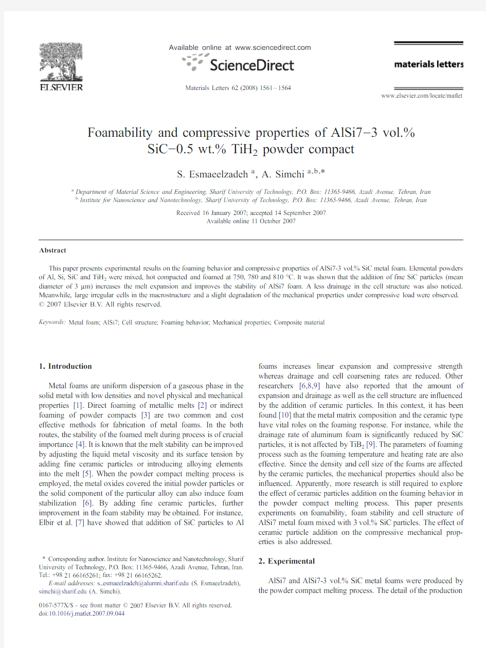
Fig.1shows the expansion of AlSi7and AlSi7-SiC precursors versus time at different foaming temperatures obtained by the expandometer
instrument.Each graph is reproduced by averaging five foaming tests at any given condition.The maximum error of measurement is b 8%.It is seen that the addition of 3vol.%SiC particles significantly improved the maximum expansion of the AlSi7foam,and the effect became less pronounced as the foaming temperature increases.This observation is linked to the melt viscosity.It is known that the presence of solid particles increases the bulk viscosity of liquids [13].Therefore,the higher viscosity of the melt containing ceramic particles improves capturing of the released gas from the foaming agent.Since the viscosity of aluminum melt decreases with increasing temperature,the positive influence of SiC particles should be lower at higher foaming temperatures.
Fig.1also shows that in the all examined foaming experiments,a drop in the expansion curve occurred after passing the maximum expansion time.This drop is an indicator of melt drainage and cell structure collapse during processing.Evidently,metal foams are more stable when the amount of the reduced expansion decreases.Therefore,it becomes apparent that the addition of SiC particles not only enhances the amount of maximum expansion,but also improves the foam stability.To characterize the stability of different foams quantitatively,the amount of reduced expansion was determined.This could be done by calculating the difference between the integral of expansion –time curve of the examined foams and fully stable foams (without any collapse)[14].If the stability parameter (S )is defined as the difference between these two integrals,the higher S-value means worse stability because it indicates a higher melt drainage occurring upon processing.Based on the data presented in Fig.1,the stability parameter (S )of different examined foams was determined.The results are reported in Table 1.First at all,it appears that the stability parameter of AlSi7-SiC composite foams is lower than that of AlSi7(ΔS N 0);the stability of AlSi7foams is improved by introducing SiC particles.On the other hand,it is seen that with increasing temperature,the amount of ΔS increases,i.e.the difference between the stability parameter of the AlSi7foam with and without SiC becomes higher.This indicates that the effect of solid particle addition at higher temperatures is more pronounced.The other point that should be noticed is the dependency of S -value to temperature.While the stability of AlSi7-SiC foam is improved as the temperature increases (lower S value at higher temperature),the stability of AlSi7foam is decreased (higher S value at higher temperature).3.2.Cell structure
The effect of SiC addition on the cell structure of AlSi7foam is shown in Fig.2.The structure of AlSi7illustrates relatively uniform cells.A dense layer at the bottom of the specimen,which shows the melt drainage,is also visible.When 3vol.%SiC particles were introduced,larger irregular cells were formed and the amount of drainage decreased.It was shown elsewhere [14]that in AlSi7-SiC foams,SiC particles are gathered within the cell walls during foaming.This observation indicates that the aluminum melt wetted the ceramic particles;otherwise,the particles should be located at the gas-metal interface.It is known that the wettability of SiC particles by pure aluminum melt is low,i.e.the contact angle is 150°at 900°C [15].A better wettability of AlSi7is related to the dissolved Si,which reduces the surface tension of aluminum [15]
and
Fig.1.AlSi7and AlSi7-SiC expansion at different foaming temperatures.
Table 1
Effect of SiC addition on the stability parameter (S )of AlSi7metal foam Temperature (°C)AlSi7AlSi7-SiC ΔS Improvement (%)750135±11123±7129780199±25104±189548810
225±17
72±20
153
68
1562S.Esmaeelzadeh,A.Simchi /Materials Letters 62(2008)1561–1564
prevent formation of Al 4C 3at the interface [16].If Al melt wets the ceramic particles,the presence of the solid particles increases the viscosity of the system,thereby contributing in foaming by decreasing the melt drainage.On the other hand,the particles increase the cell wall thinning rate [17],and as a consequence,larger cells are formed.
3.3.Mechanical properties
Fig.3shows the compressive stress –strain curves of AlSi7and AlSi7-SiC foams produced,respectively,at 750and 810°C.These tests were repeated three times to check the reproducibility and reliability of the results.As it is seen,the addition of SiC particles increased the yield strength of AlSi7for about 18%.The slope of the semi-plateau region was also increased whereas the densification strain was decreased.Although higher strength was achieved,the maximum energy absorption efficiency [18]was slightly reduced (~5%).The stress –strain curve of the AlSi7-SiC foam exhibits more fluctuations in the semi-plateau region,indicating non-uniformity in the plastic deformation during loading [19].
This can be due to non-uniform cell structure of the composite foam compared with that of AlSi7(Fig.2).
4.Conclusion
Effects of SiC addition on the cell structure,foaming behavior and mechanical properties of AlSi7metal foams were studied.It was found that SiC particles are gathered within the cell walls.Under this condition,the particles increase the bulk viscosity of the metal melt and improve the maximum expansion and the foam stability.It was also shown that SiC particles influence the cell structure of AlSi7foam.While the drainage is reduced,the cells became larger and non-uniform.The composite foam exhibits more brittle and non-uniform deformation with less energy absorption efficiency as compared with AlSi7foam.Acknowledgment
The authors sincerely acknowledge with thank Dr. D.Lehmhus (Fraunhofer Institute IFAM,Bremen,Germany)for his assistance in the experimental work and advice during valu-able discussion.References
[1]J.Banhart,Prog.Mater.Sci.46(2001)559.
[2]G.Kaptay,in:J.Banhart,M.Ashby,N.Fleck (Eds.),Cellular Metals and
Metal Foaming Technology,MIT,Berlin,2001,p.117.[3]I.Duarte,J.Banhart,Acta Mater.48(2000)23349.
[4]J.Banhart,in:H.Nakajimat,N.Kanetake (Eds.),Porous Metals and Metal
Foaming Technology (MetFoam2005/JIMIC-4),Kyoto,21–23September 2005,The Japan Institute of Metals,2006,pp.75–86.
[5]J.Banhart,J.Baumeister,M.Weber,Advanced PM Materials,1995,p.201,
Birmingham.
[6]M.Arnold,C.K?rner,R.F.Singer,in:J.Banhart,N.Fleck,A.Mortensen
(Eds.),Cellular Metals-Manufacture,Production,Application,MIT,Berlin,2003,p.
71.
Fig.2.Optical macrographs show the cell structure of AlSi7(a)and AlSi7-SiC
(b).
https://www.360docs.net/doc/a115762802.html,pressive stress –strain curves of the examined foams.The foaming temperature for AlSi7and AlSi7-3vol%SiC foams were 750and 810°C,respectively.The foaming time was about 15min.
1563
S.Esmaeelzadeh,A.Simchi /Materials Letters 62(2008)1561–1564
[7]E.Elbir,S.Yilmaz,A.K.Toksoy,M.Guden,I.W.Hall,J.Mater.Sci.38
(2003)4745.
[8]A.R.Kennedy,S.Asavavisithchai,in:J.Banhart,N.Fleck,A.Mortensen
(Eds.),Cellular Metals-Manufacture,Production,Application,MIT, Berlin,2003,p.147.
[9]A.R.Kennedy,S.Asavavisithchai,Scripta Mater.50(2004)115.
[10]P.Weigand,Ph.D.Thesis,IFAM,Bremen(1999).
[11]S.Esmaeelzadeh,A.Simchi,D.Lehmhus,Porous Metals and Metal
Foaming Technology,JIMIC,Osaka,2006,in print.
[12]D.Lehmhus,G.Rausch,Adv.Eng.Mater.6(5)(2004)313.
[13]R.M.German,A.Bose,Injection Molding of Metals and Ceramics,Metal
Powder Industries Federation,NY,USA,1997.[14]S.Esmaeelzadeh,A.Simchi,D.Lehmhus,Mater.Sci.Eng.A424(2006)
290.
[15]J.Hashim,L.Loony,M.S.J.Hashmi,J.Mat.Proc.Tech.119(2001)324.
[16]https://www.360docs.net/doc/a115762802.html,urent,D.Chatain,N.Eustathopoulos,J.Mater.Sci.22(1987)244.
[17]V.Gergely,H.P.Degischer,T.W.Clyne,https://www.360docs.net/doc/a115762802.html,pos.Mater.3(2000)
797.
[18]S.W.Ip,Y.Wang,J.M.Toguri,Can.Metall.Q.27(1)(1999)81.
[19]B.Foroughi,B.Kriszt,H.P.Degischer,in:J.Banhart,M.Ashby,N.Fleck
(Eds.),Cellular Metals and Metal Foaming Technology,MIT,Bremen, 2001,p.265.
1564S.Esmaeelzadeh,A.Simchi/Materials Letters62(2008)1561–1564
土的压缩性实验报告doc
土的压缩性实验报告 篇一:土力学实验报告 土力学实验报告 班级:姓名:学号:小组成员: 中国矿业大学建筑工程学院岩土工程研究所二〇一四年十二月 试验一含水量试验 一、目的 本试验之目的在于测定土的含水量,借与其它试验相配合计隙比及饱和度等;并查表确定地基土的容许承载力。 二、解释 (1)含水量w是土中水的质量与干土颗粒质量之比,用百分数表示。 (2)本方法适用于有机物含量不超过干土重5%的土。若土中有机物含量在5~l0%之间,应将烘干温度控制在65-70℃,并在记录中注明)。 三、设备 (1)有盖的称量盒数只;(2)天平,感量0.01克;(3)烘箱(温度100~110℃)(4)干燥器(内有干燥剂CaCl2)。 四、操作步骤 (1)选取具有代表性的土样l5-30克(砂土适当多取)
放入称量盒。盖好盒盖,称盒加湿土质量。 (2)打开盒盖,放入烘箱。在105~110℃下烘至恒重。烘干的时间一般为:粘土、粉土不得少于8小时;砂土不得少于6小时。 (3)将烘好的试样连同称量盒一并放入干燥器内,让其冷却至室温。(4)从干燥器内取出试样,称盒加干土质量。 (5)实验称量应准确至0.01克以上并进行2次平行测定,取平均值。(6)按下式计算含水量: 12 w?2??100% 式中: w——含水量,%; m1——称量盒加湿土质量,g; m2——称量盒加干土质量,g: m——称量盒质量,g(根据盒上标号查表)。 本试验须进行2次平行测定,其平行误差允许值;当含水量w小于5%时,允许平行误差为0.3%; 当含水量w等于或大于5%而小于40%时允许平行误差为l%;当含水量w等于或大于40% 时,允许平行误差为2%。 五、注意事项 (1)称量盒使用前应先检查盒盖与盒体号码是否一致,
骨质疏松椎体压缩性骨折 诊疗指南及技术操作规范
骨质疏松症椎体压缩性骨折诊疗指南 骨质疏松症是指:骨量减少、骨组织显微结构破坏、骨脆性增加、骨强度下降、骨折风险性增加为特征的全身性、代谢性骨骼系统疾病;当骨质疏松症导致骨密度和骨质量下降,骨强度减低时,轻微外力即可发生的骨折,该骨折累计脊柱时,称为骨折疏松椎体压缩性骨折(OVF),脊柱是骨质疏松症骨折的常发部位。(附:诊疗流程与诊疗指南、PVP技术规范) 一、OVF诊疗流程
二.OVF诊治指南 (一)临床特点 疼痛、脊柱变形和发生脆性骨折是骨质疏松症最典型的临床表现。但许多骨质疏松症患者早期常无明显的自觉症状,往往在骨折发生后经X线或骨密度检查时才发现已有骨质疏松改变。 1、疼痛:患者可有腰背酸痛或周身酸痛,负荷增加时疼痛加重或活动受限,严重时翻身、起坐及行走有困难。 2、脊柱变形:骨质疏松严重者可有身高缩短和驼背。椎体压缩性骨折会导致胸廓畸形,腹部受压,影响心肺功能等。 3、骨折:轻度外伤或日常活动后发生骨折为脆性骨折。发生脆性骨折的常见部位为胸、腰椎。发生过一次脆性骨折后,再次发生骨折的风险明显增加。 (二)实验室检查 1. 根据鉴别诊断需要可选择检测血、尿常规,肝、肾功能,血糖、钙、磷、碱性磷酸酶、性激素、25(OH)D和甲状旁腺激素等。 2. 根据病情、药物选择、疗效观察和鉴别诊断需要,有条件的单位可分别选择下列骨代谢和骨转换的指标(包括骨形成和骨吸收指标)。这类指标有助于骨转换的分型、骨丢失速率及老年妇女骨折的风险性评估、病情进展和干预措施的选择和评估。临床常用检测指标:血清钙、磷、25-羟维生素D和1,25-双羟维生素D。骨形成指标:血清碱性磷酸酶(ALP),骨钙素(OC)、骨源性碱性磷酸酶(BALP),l 型前胶原C端肽(PICP)、N端肽(PINP);骨吸收指标:空腹2小时的尿钙/肌酐比值,或血浆抗酒石酸酸性磷酸酶(TPACP)及l型胶原C端肽(S-CTX),尿吡啶啉(Pyr)和脱氧吡啶啉(d-Pyr),尿I型胶原C端肽(U-CTX)和N端肽(U-NTX)等。 (三)物理学检查 1. 骨质疏松症的物理学检查 骨密度检测:X线、单光子吸收骨密度仪、双光子吸收骨密度仪、双能骨密度仪、定量CT和PET—CT。
详解骨质疏松性椎体骨折骨不连
详解骨质疏松性椎体骨折骨不连 骨质疏松性椎体骨折骨不连(osteoporotic vertebral fracture nonunion)最早由德国医生Kummel首先描述该病的发病过程,并命名为Kummel病。其典型特征是受到轻微损伤后,经过数周无症状期逐渐出现的腰背部疼痛、椎体塌陷和进行性加重的后凸畸形。回顾文献,既往有多种称谓表示这一含义,如“椎体内裂隙征”、“椎体内真空征”、“椎体内裂隙真空征”、“创伤后椎体骨坏死”等,大部分均与椎体内的真空征相关。 危险因素 骨质疏松性椎体骨折骨不连的发病机制尚不完全明了,有学者认为其源于血管损伤,是一种椎体迟发性的缺血性坏死。感染、服用类固醇类药物、放疗、脉管炎、胰腺炎、肝硬化、动脉硬化、酗酒、高龄与骨质疏松等被认为是这种疾病的高危因素。另外,骨折椎体磁共振T2加权像呈现局限的高信号或弥散的低信号是发生椎体骨不连的危险因素。 发病率 过去认为骨质疏松性椎体骨折骨不连较为少见,但近年来随着医学影像技术的发展,其诊断率不断提高。有人报道骨质疏松性椎体骨折患者行6个月非手术治疗后骨不连的发生率为 13.5%。 临床表现 骨质疏松性椎体骨折骨不连呈进行性进展,难以自行愈合,可引起患者长期腰痛不适,卧床休息时腰痛消失或明显减轻,但翻身可引起疼痛,坐、立、走时时疼痛加重。患者常表述“只要整天躺在床上就是一个健康的人”。另外,塌陷的椎体还会压迫脊髓,甚至导致瘫痪。一般骨质疏松性椎体骨折骨不连早期阶段椎体完好无损或轻微骨折,中期出现椎体塌陷与活动性不稳,后期出现明显的椎体塌陷与进展性后凸畸形。 诊断标准 诊断骨质疏松性椎体骨折骨不连应满足以下几个特点:1.持续数周或数月的腰背部疼痛;2.MRI显示椎体内有界限清晰的液性信号区域,见图4;3.X 线、CT检查显示椎体裂隙征,边缘硬化甚至假关节形成,CT 更明显;4.动力位 X 线显示终板相对运动和 /或椎体前壁高度改变,假关节形成,见图1和图2。椎体骨折骨不连X线片或CT上呈典型裂隙样改变,见图3,当椎体内裂隙内为液体时,MRI表现为界限清晰的T2加权像高信号,增强MRI显示椎体内裂隙状未增强区;当裂隙内为气体时,T1、T2均呈低信号。椎体内裂隙气体和液体量随着病情进展而变化,裂隙内逐渐被液体填充,主要成分为浆液性积液和坏死的肉芽组织,在MRI上显示为典型的气液平面。也有研究发现骨折椎内裂隙在患者脊柱过
流体力学第七章不可压缩流体动力学基础
第七章不可压缩流体动力学基础在前面的章节中,我们学习了理想流体和粘性流体的流动分析,按照水力学的观点,求得平均量。但是,很多问题需要求得更加详细的信息,如流速、压强等流动参数在二个或三个坐标轴方向上的分布情况。本章的内容介绍流体运动的基本规律、基本方程、定解条件和解决流体问题的基本方法。 第一节流体微团的运动分析 运动方式:①移动或单纯的位移(平移)②旋转③线性变形④角变形。位移和旋转可以完全比拟于刚体运动,至于线性变形和脚变形有时统称为变形运动则是基于液体的易流动性而特有的运动形式,在刚体是没有的。 在直角坐标系中取微小立方体进行研究。
一、平移:如果图(a )所示的基体各角点的质点速度向量完全相同时,则构成了液体基体的单纯位移,其移动速度为z y x u u u 、、。基体在运动中可能沿直线也可能沿曲线运动,但其方位与形状都和原来一样(立方基体各边的长度保持不变)。 二、线变形:从图(b )中可以看出,由于沿y 轴的速度分量,B 点和C 点都比A 点和D 点大了 dy y u y ??,而 y u y ??就代表1=dy 时液体基体运动时,在单位时间内沿 y 轴方向的伸长率。 x u x ??,y u y ??,z u z ?? 三、角变形(角变形速度) d d d D C A B C D B A
dt y u dy dt dy y u d x x ??=???=α dt x u dx dt dx x u d y y ??=???=β θβθα+=-d d 2 βαθd d -= ∴ 角变形: ???? ????+??=+=-=x u y u d d d y x z 212βαθαθ ?? ? ????+??= x u z u z x y 21θ ???? ????+??=y u z u z y x 21θ 四、旋转(旋转角速度) ??? ? ????-??=-=y u x u x y z 21θω ??? ? ????-??=z u y u y z x 21ω 即, ?? ? ????-??=x u z u z x y 21ω z y x u u u z y x k j i ??????= 21ω 那么,代入欧拉加速度表达式,得: z x x x x x x z y y z z y y y y y y y x z z x x z z z z z z z y x x y y x x y du u u u u u u u dt t x u u u u u u u u dt t y u u u u u u u u dt t z αθθωωαθθωωαθθωω??? = =++++-???? ????==++++-???? ????==++++-? ??? 各项含义: (1) 平移速度 (2)线变形运动所引起的速度增量
经皮椎体成形术治疗骨质疏松性椎体压缩性骨折的临床疗效分析
经皮椎体成形术治疗骨质疏松性椎体压缩性骨折的临床疗效分析 摘要目的研究分析经皮椎体成形术(PVP)治疗骨质疏松性椎体压缩性骨折(OVCF)的临床疗效。方法116例骨质疏松性椎体压缩性骨折患者,依据治疗方法不同分为研究组(60例)与对照组(56例)。研究组患者实施PVP 治疗,对照组患者实施常规保守治疗。观察比较两组患者的治疗效果。结果治疗后,研究组总有效率95.00%高于对照组的80.36%,差异具有统计学意义(P <0.05)。治疗前两组视觉模拟评分法(V AS)评分比较差异无统计学意义(P>0.05);治疗后研究组V AS评分低于对照组,差异具有统计学意义(P<0.05)。治疗前两组椎体前缘高度、后凸Cobb角比较差异均无统计学意义(P>0.05);治疗后,研究组椎体前缘高度、后凸Cobb角优于对照组,差异均具有统计学意义(P<0.05)。结论骨质疏松性椎体压缩性骨折患者实施PVP治疗,具有良好的临床效果,值得推广。 关键词椎体压缩性骨折;骨质疏松;经皮椎体成形术 【Abstract】Objective To study and analyze the clinical efficacy of percutaneous vertebroplasty (PVP)in the treatment of osteoporotic vertebral compression fractures (OVCF). Methods A total of 116 patients with osteoporotic vertebral compression fractures were divided by different treatment methods into research group (60 cases)and control group (56 cases). The research group received PVP treatment,and the control group received conventional conservative treatment. Treatment effect in two groups was observed and compared. Results After treatment,the research group had higher total effective rate as 95.00% than 80.36% in the control group,and the difference was statistically significant (P<0.05). Before treatment,both groups had no statistically significant difference in visual analogue scale (V AS)score (P>0.05). After treatment,the research group had lower V AS score than the control group,and the difference was statistically significant (P<0.05). Before treatment,both groups had no statistically significant difference in vertebral anterior height and kyphosis Cobb angle (P>0.05). After treatment,the research group had better vertebral anterior height and kyphosis Cobb angle than the control group,and the difference was statistically significant (P<0.05). Conclusion PVP provides remarkable clinical effect for patients with osteoporotic vertebral compression fractures,and it is worthy of promotion. 【Key words】Vertebral compression fractures;Osteoporotic;Percutaneous vertebroplasty 骨质疏松在临床骨科中十分常见,该疾病患者发病后易并发多种并发症,其中椎体压缩性骨折就是该疾病患者常见的一种并发症[1]。而骨质疏松性椎体压缩性骨折对于患者的身体健康状况及生活质量等均具有严重的影响,故及时对患者实施准确的诊治干预等尤为重要。本研究中就对PVP手术治疗骨质疏松性椎体压缩性骨折患者的临床效果进行观察评价,具体报告如下。
30例经皮椎体成形术治疗老年性骨质疏松性椎体压缩性骨折临床观察
龙源期刊网 https://www.360docs.net/doc/a115762802.html, 30例经皮椎体成形术治疗老年性骨质疏松性椎体压缩性骨折临床观察 作者:刘聚红 来源:《中国实用医药》2016年第11期 【摘要】目的观察经皮椎体成形术治疗老年性骨质疏松性椎体压缩性骨折临床效果。方法 30例老年性骨质疏松性椎体压缩性骨折患者,行经皮椎体成形术治疗,分析其临床效果。结果经3个月治疗后,显效17例(56.67%),有效12例(40.00%),无效1例 (3.33%),总有效率为96.67%。结论经皮椎体成形术治疗老年性骨质疏松性椎体压缩性骨折,其治疗效果显著,可有效改善患者的临床症状,提高患者的生活质量,值得在临床上推广使用。 【关键词】老年性椎体压缩性骨折;骨质疏松;经皮椎体成形术;临床效果 DOI:10.14163/https://www.360docs.net/doc/a115762802.html,ki.11-5547/r.2016.11.139 过去传统的治疗老年骨质疏松性椎体压缩性骨折方法,术后患者多表现为骨质脱钙,更进一步增大了骨骼脆性,对老年患者的生活构成严重威胁[1]。本文现选取本院收治的30例经皮椎体成形术治疗老年性骨质疏松性椎体压缩性骨折患者为研究对象,观察经皮椎体成形术 治疗老年性骨质疏松性椎体压缩性骨折临床效果,详情如下。 1 资料与方法 1. 1 一般资料选取本院2013年6月~2015年6月收治的30例老年性骨质疏松性椎体压缩性骨折患者为研究对象,其中男14例,女16例,年龄62~85岁,平均年龄71岁。病情类型:12例患者的椎体压缩性骨折为1处, 11例患者的椎体压缩性骨折为2处, 7例患者的椎体压缩性骨折为3处,其中胸椎体压缩性骨折3例,腰椎椎体压缩性骨折27例。 1. 2 手术方法对患者均行经皮椎体成形术治疗:①术前准备:器械准备,即灌注剂、穿 刺针、数字减影X光机、注射器。调制骨水泥Ⅱ灌注剂比例为2:1;选择合适的13G带蕊穿刺针,穿刺针长度10~15 cm;数字减影X光机型号为C型臂AXIOM-Artis。注射器选择旋 转加压式。②建立静脉通路:术前,建立两条静脉通道,给予浓度为10%的葡萄糖溶液20 ml 混合地塞米松5 mg,静脉注射,为预防过敏及应激反应;用药:浓度为0.9%生理盐水100 ml混合头孢曲松钠针1.0 g,采取术前30 min静脉滴注,其目的为预防局部感染。③经皮椎 体成形术:确认手术室处于无菌环境,患者取俯卧位,行常规消毒铺巾,并采取1%利多卡因与脊柱病变位置行局部麻醉,并于该位置处行穿刺针穿刺,在C型臂透视位置满意后,调制骨水泥Ⅱ灌注剂,使之呈牙膏状,并采取注射器在高压下,通过穿刺针灌注入患者病变椎体内(3~5 ml),灌注结束,拔除穿刺针,再次C型臂透视满意后行包扎止血处理。④术
不可压缩流体动力学基础习题答案
不可压缩流体动力学基础 1.已知平面流场的速度分布为xy x u x +=2,y xy u y 522+=。求在点(1,-1)处流体微团的线变形速度,角变 形速度和旋转角速度。 解:(1)线变形速度: y x x u x x +=??= 2θ 54+=??= xy y u y y θ 角变形速度:()x y y u x u x y z +=??? ? ????+??=222121ε 旋转角速度: ()x y x u x u x y z -=???? ????-??=222 1 21ω 将点(1,-1)代入可得流体微团的 1=x θ,1=y θ;23/z =ε;21/z =ω 2.已知有旋流动的速度场为322+=y u x ,x z u y 32+=,y x u z 32+=。试求旋转角速度,角变形速度和 涡线方程。 解:旋转角速度: 2 1 21=???? ????-??=z u y u y z x ω 2 121=??? ????-??=x u z u z x y ω 2 1 21=???? ????-??=y u x u x y z ω 角变形速度:2 5 21=???? ????+??=z u y u y z x ε 2 521=??? ????-??=x u z u z x y ε 25 21=??? ? ????-??=y u x u x y z ε 由 z y x dz dy dx ωωω= = 积分得涡线的方程为: 1c x y +=,2c x z +=
3.已知有旋流动的速度场为2 2z y c u x +=,0=y u ,0=z u ,式中c 为常数,试求流场的涡量及涡线方程。 解:流场的涡量为: 0=??-??= z u y u y z x Ω 2 2 z y cz x u z u z x y +=??-??= Ω 2 2z y cy y u x u x y z +-=??- ??= Ω 旋转角速度分别为: 0=x ω 2 2 2z y cz y += ω 2 22z y cy z +- =ω 则涡线的方程为: c dz dy z y +=? ?ωω 即 c y dz z dy +-=?? 可得涡线的方程为: c c y =+22 4.求沿封闭曲线 2 22b y x =+,0=z 的速度环量。(1)Ax u x =,0=y u ;(2)Ay u x =,0=y u ;(3) 0=y u ,r A u =θ。其中A 为常数。 解:(1)由封闭曲线方程可知该曲线时在z =0的平面上的圆周线。 在z =0的平面上速度分布为: Ax u x =,0=y u 涡量分布为: 0=z Ω 根据斯托克斯定理得: 0==?z A z s dA ΩΓ (2)涡量分布为: A z -=Ω 根据斯托克斯定理得: 2b A dA z A z s πΩΓ-==?
骨质疏松性椎体压缩骨折的分类及治疗
【关键词】骨质疏松椎体压缩骨折 骨质疏松性椎体压缩骨折临床治疗一般分为保守治疗和手术治疗两大类。保守治疗如卧床休息、口服止痛药物和佩带矫形支具等,由于长时间卧床,易发生褥疮、泌尿系感染等并发症,更重要的是由于长期缺乏有效的锻炼,骨质疏松将进一步加重,又易发生再骨折,形成恶性循环,使疼痛加剧。其他治疗骨质疏松方法如激素疗法、服用钙剂、降钙素等长期有一定效果,但短期镇痛效果却不好。传统的开放手术创伤大,而且因为骨质疏松本身的特点,内固定物极易发生松动。经皮椎体成形术(percutaneous vertebroplasty,pvp)及经皮椎体后凸成形术(percutaneous kyphoplasty,pkp)为ovcfs的治疗提供了新的方法。pvp是在影像设备的监视下,利用微创技术将骨水泥等生物材料经皮肤及椎弓注入椎体,增加病变椎体强度,防止椎体进一步塌陷和再骨折,解除疼痛并改善躯体功能,使患者能早期下床活动[3,4]。1998年美国kyphon公司在pvp的基础上研制出一种可扩张的球囊,经皮经椎弓根将球囊置入椎体,加压球囊膨胀使塌陷椎体复位,并在椎体内形成空腔,再填充骨水泥,矫正后凸畸形,并逐渐完善至现今的pkp技术。其能明显缓解疼痛,维持椎体稳定性,恢复椎体的高度,并且避免了骨水泥渗漏等并发症,临床效果满意,已有很多报道证明其有效性[5]。骨质疏松性椎体压缩骨折的分类方法很多,常用的有genant半定量法。在标准侧位x线片上,如果t4~l4椎体的形态及大小正常,则为0级(正常);椎体高度降低20%~25%和椎体投影面积降低10%~20%,为ⅰ级(轻度变形或ⅰ度骨折);椎体高度降低25%~40%和椎体投影面积降低20%~40%,为2级(中度变形或ⅱ度骨折);椎体高度和椎体投影面积降低大于40%,为3级(严重变形或ⅲ度骨折)。 genant半定量法比较简便、实用,但其单纯的依靠标准侧位x线片进行分级,而同等程度的压缩骨折合并的临床症状可能各不相同。heini结合骨质疏松性患者的临床特征及影像学表现,将骨质疏松性椎体压缩骨折分为四型,ⅰ型:急性或亚急性单纯椎体压缩骨折;ⅱ型:骨折后持续性椎体不稳,骨折不愈合;ⅲ型:多节段椎体压缩骨折合并进行性体位改变;ⅳ型:伴有继发性椎管狭窄,合并神经症状[6]。 目前临床对脊柱压缩骨折的治疗过程中,尚无为广大临床骨科医师所接受的分类方法,但在我们的临床实践中,感受到heini的分类方法更符合临床,故将其分类和一些文献综述如下。 1 急性或亚急性单纯椎体压缩骨折 大多数单纯椎体压缩骨折经保守治疗后疼痛缓解,但仍有1/3以上的患者持续疼痛。若任其发展,有相当部分的椎体将进一步塌陷,导致脊柱后凸畸形,发展成慢性疼痛。 1.1 临床表现急性单纯骨质疏松性椎体压缩骨折的症状基本相同,大多数为低能量骨折,表现为骨折节段的局部背痛,无脊髓和神经根受损的症状和体征。在休息后会有所缓解,但在负重或剧烈活动后会复发或加重。侧位x线片可见椎体楔形变,椎体前缘压缩,ct提示椎体后壁完整。mri检查t1加权像低信号、t2加权像高信号,提示为急性期骨折。 1.2 治疗经保守治疗4~6周无明显改善的疼痛性ovcfs,行pvp或pkp治疗是非常合适的[7,8]。大部分患者在椎体强化术后72 h内疼痛能部分甚至完全缓解。迄今还没有关于比较保守治疗和pvp/pkp治疗效果的随机对照性试验见诸于报道,但是有直接比较保守治疗和pkp疗效非随机对照试验。kasperk等[9]对两组患者的影像学检查、vas评分、日常活动能力进行比较发现,pkp组vas评分明显改善,而保守治疗组没有改变。在随访6个月内,pkp组患者因疼痛而复查的次数平均为每名患者3.3次,而对照组高达8.6次。 在nakano等[10]配对病例对照研究中发现,同保守治疗相比,利用椎体成形术治疗椎体压缩骨折,不论是术后vas评分,还是止痛药物的使用情况,或是后期脊柱后凸畸形的发生率,均有显著的优势。 对于单纯的急性或亚急性椎体压缩骨折,已有大量的研究证实pvp和pkp在缓解疼痛方面都
土的压缩性和固结理论
五 土的压缩性和固结理论 一、填空题 1.土体的压缩性被认为是由于土体中______________减小的结果。 2.土的固结系数表达式为_________,其单位是____________;时间因数的表达式为___________。 3.根据饱和土的一维固结理论,对于一定厚度的饱和软粘土层,当t=0和0≤z ≤H 时,孔隙水压力u=______________;当t=∞和0≤z ≤H 时,孔隙水压力u=__________________。 4.在土的压缩性指标中,s E 和a 的关系为____________________;S E 和0E 的关系为_______。对后者来说,其关系只在理论上成立,对_________土相差很多倍,对__________土则比较接近。 5.土的压缩性是指___________。 6.压缩曲线的坡度越陡,说明随着压力的增加,土孔隙比的减小愈___________,因而土的压缩性愈_________________。反之,压缩曲线的坡度越缓,说明随着压力的增加,土的孔隙比的减小愈___________,因而土的压缩性愈___________。《规范》采用21-a 来评价土的压缩性高低,当21-a _____________时,属低压缩性土;当21-a _____________时,属中压缩性土;21-a _____________时,属高压缩性土。 7.土的压缩指数的定义表达式为___________。 8. 超固结比OCR 指的是______和______之比;根据OCR 的大小可把粘性土分为______、______、______三类;1OCR <的粘性土属______土。 9.压缩系数______,压缩模量______,则土的压缩性越高。这两个指标通过______试验,绘制______曲线得到。 答案:1.孔隙体积 2.w a e k γ) 1(C 1V += 年2m 2T h t c v v = 3.z σ 0 4.a e E s 11+= s E E β=0 硬土 软土 5土在压力作用下体积减小的特征 6.显著 高 小 低 21-a <0.11 M -pa 0.11 M -pa ≤21-a <0.51 M -pa 21-a ≥0.51 M -pa 7.1 2 211 221C lg lg lg p p e e p p e e C -=--= 8.先期固结压力、现在土的自重应力、正常固结土、超 固结土、欠固结土、欠固结土 9.越大、减小、压缩、e p - 二、选择题 1.下列说法中,错误的是( )。 (A )土在压力作用下体积会缩小 (B )土的压缩主要是土中孔隙体积的减小
研究土压缩性的试验及指标
第二节 研究土压缩性的试验及指标 一、室内侧限压缩试验及压缩模量 土的压缩性是指在压力作用下体积压缩小的性能。从理论上,土的压缩变形可能是:(1)土粒本身的压缩变形;(2)孔隙中不同形态的水和气体的压缩变形;(3)孔隙中水和气体有一部分被挤出,土的颗粒相互靠拢使孔隙体积减小。 土的固结——土体在压力作用下其压缩量随时间增长的过程。 侧限压缩试验分为:(1)慢速压缩试验法;(2)快速压缩试验法 侧限——限制土样侧向变形,通过金属环刀来实现。 试验目的——研究测定试样在侧限与轴向排水条件下的变形和压力,或孔隙比和压力的关系,变形和时间的关系,以便计算土的各项压缩指标。 试验设备——固结仪。 (一)e -p 曲线及有关指标 要绘制e -p 曲线,就必须求出各级压力作用下的孔 隙比——e 。 如何求e ?看示意图: 设试样截面积为A ,压缩前孔隙体积为0v V ,土粒体积为0s V ,土样高度为0H ,孔隙比为0e (已测出)。压缩稳定后的孔隙体积为v V ,土粒体积为s V ,土样高度为H H H ?-='0,孔隙比为e ,H Λ为某级压力下样式高度变化(可以测出)。依侧限压缩试验原理可知:土样压缩前后试样截面积A 不变,s s V V =0,则有: e H H e H +Λ-+=11000 则可得:)1(00 0e H H e e +Λ-= 利用上式计算各级荷载P 作用下达到的稳定孔隙比e ,可绘制如图4-3所示的e -p 曲线,该曲线亦被称为压缩曲线。 1、压缩系数α dp de -=α α——压缩系数,MP a -1,负号表e 随P 的增长而减小。 当压力变化范围不大时,土的压缩曲线可近似用图4-4中的M 1M 2割线代替。
土的压缩性及固结理论
第4章土的压缩性及固结理论 基本内容 这是本课程的重点。在学习土的压缩性指标确定方法的基础上,掌握地基最终沉降量计算原理和地基固结问题的分析计算方法。 学习要求: 1. 掌握土的压缩性与压缩性指标确定方法; 2.掌握有效应力原理; 3.掌握太沙基一维固结理论; 4.1 概述(outline) 土在自重应力或附加应力作用下,地基土要产生附加变形,包括体积变形和形状变形。对于土来说,体积变形通常表现为体积缩小。我们把这种在外力作用下土体积缩小得特性称为土的压缩性(compressibility)。 It is well recognized that the deformations will be induced in ground soil under self-weight or net contact pressure. The load-induced soil deformations can be divided into volumetric deformation and deviatoric deformation (namely, angular distortion or deformation in shape). The volumetric deformation is mainly caused by the normal stress, which compact the soil, resulting in soil contraction instead of soil failure. The deviatoric deformation is caused by the shear stress. When the shear stress is large enough, shear failure of the soil will be induced and soil deformation will develop continuously. Usually shear failure over a large area is not allowed to happen in the ground. 土的压缩性主要有两个特点: (1)土的压缩性主要是由于孔隙体积减少而引起的; (2)由于孔隙水的排出而引起的压缩对于饱和粘土来说需要时间,将土的压缩随时间增长的过程称为土的固结。 在建筑物荷载作用下,地基土主要由于压缩而引起的竖直方向的位移称为沉降。 研究建筑物沉降包含两方面的内容: 一是绝对沉降量的大小,亦即最终沉降; 二是沉降与时间的关系,主要介绍太沙基的一维固结理论 土体产生体积缩小的原因: (1)固体颗粒的压缩; (2)孔隙水和孔隙气体的压缩,孔隙气体的溶解;孔隙水和孔隙气体的排出。由于纯水的弹模约为2×10⁶kPa,固体颗粒的弹模为9×l 07kPa,土粒本身和孔隙中水的压缩量,在工程压力(100~600kPa)范围内,不到土体总压缩量的1/400,因此常可略不计。所以,土体压缩主要来自孔隙水和土中孔隙气体的排出。孔隙中水和气体向外排出要有一个时间过程。因此土的压缩亦要一段时间才能完成。把这一与时间有关的压缩过程称为固结。 土体的变形计算,需要取得土的压缩性指标,可以通过室内侧限压缩试验和现场原位试验得到。 室内压缩试验亦称固结试验,是研究土压缩性最基本的方法。 现场载荷试验是在工程现场通过千斤顶逐级对置于地基土上的载荷板施加荷载,观测记录沉降随时间的发展以及稳定时的沉降量s,并绘制成p-s曲线,即获得地基土载荷试验的结果。 反映土的压缩性的指标主要有压缩系数、压缩模量、压缩指数和变形模量。土的压缩性的高低,常用压缩性指标定量表示,压缩性指标,通常由工程地质勘察取天然结构的原状土样进行. Characteristic of soil compression (1)Compression of soil is mainly due to the decrease of void volume. (2)The compression for a clay increases with the times (consolidation) Ground soil will deform vertically due to structure load. The contents on studying structure settlement include 1 The absolute settlement (final settlement) 2 Relationship between settlement and time. Introducing terzaghi’s 1D consolidation theory Reasons of volumetric reduction of soil mass 1 The compressive deformation of the soil particles. 2 The compressive deformation of the pore water and air. The partial discharge of the pore water and air.
骨质疏松性椎体压缩骨折的分类及治疗
[ 字号:大 中 小 ] 骨折是骨质疏松 最常见、最严重的并发症,在美国大约每年有70 000 例骨质疏松性椎体压缩骨折(osteoporotic verterbral compressiou fractures ,OVCFs)发生,而且20%的患者在一年之内继发其他部位骨折。其中2/3的OVCFs 没有明显的临床症状,但仍有1/3的骨折会合并疼痛、后凸畸形、功能障碍等后遗症,严重影响患者的生活质量[1,2]。 骨质疏松性椎体压缩骨折临床治疗一般分为保守治疗和手术治疗两大类。保守治疗如卧床休息、口服止痛药物和佩带矫形支具等,由于长时间卧床,易发生褥疮、泌尿系感染等并发症,更重要的是由于长期缺乏有效的锻炼,骨质疏松将进一步加重,又易发生再骨折,形成恶性循环,使疼痛加剧。其他治疗骨质疏松方法如激素疗法、服用钙剂、降钙素等长期有一定效果,但短期镇痛效果却不好。传统的开放手术创伤大,而且因为骨质疏松本身的特点,内固定物极易发生松动。经皮椎体成形术(percutaneous vertebroplasty ,PVP)及经皮椎体后凸成形术(percutaneous kyphoplasty ,PKP)为OVCFs 的治疗提供了新的方法。PVP 是在影像设备的监视下,利用微创技术将骨水泥等生物材料经皮肤及椎弓注入椎体,增加病变椎体强度,防止椎体进一步塌陷和再骨折,解除疼痛并改善躯体功能,使患者能早期下床活动[3,4]。1998年美国Kyphon 公司在PVP 的基础上研制出一种可扩张的球囊,经皮经椎弓根将球囊置入椎体,加压球囊膨胀使塌陷椎体复位,并在椎体内形成空腔,再填充骨水泥,矫正后凸畸形,并逐渐完善至现今的PKP 技术。其能明显缓解疼痛,维持椎体稳定性,恢复椎体的高度,并且避免了骨水泥渗漏等并发症,临床效果满意,已有很多报道证明其有效性[5]。 骨质疏松性椎体压缩骨折的分类方法很多,常用的有Genant 半定量法。在标准侧位X 线片上,如果T4~L4椎体的形态及大小正常,则为0级(正常);椎体高度降低20%~25%和椎体投影面积降低10%~20%,为Ⅰ级(轻度变形或Ⅰ度骨折);椎体高度降低25%~40%和椎体投影面积降低20%~40%,为2级(中度变形或Ⅱ度骨折);椎体高度和椎体投影面积降低大于40%,为3级(严重变形或Ⅲ度骨折)。 Genant 半定量法比较简便、实用,但其单纯的依靠标准侧位X 线片进行分级,而同等程度的压缩骨折合并的临床症状可能各不相同。Heini 结合骨质疏松性患者的临床特征及影像学表现,将骨质疏松性椎体压缩骨折分为四型,Ⅰ型:急性或亚急性单纯椎体压缩骨折;Ⅱ型:骨折后持续性椎体不稳,骨折不愈合;Ⅲ型:多节段椎体压缩骨折合并进行性体位改变;Ⅳ型:伴有继发性椎管狭窄,合并神经症状[6]。 目前临床对脊柱压缩骨折的治疗过程中,尚无为广大临床骨科医师所接受的分类方法,但在我们的临床实践中,感受到Heini 的分类方法更符合临床,故将其分类和一些文献综述如下。 1 急性或亚急性单纯椎体压缩骨折 大多数单纯椎体压缩骨折经保守治疗后疼痛缓解,但仍有1/3以上的患者持续疼痛。若任其发展,有相当部分的椎体将进一步塌陷,导致脊柱后凸畸形,发展成慢性疼痛。 1.1 临床表现 急性单纯骨质疏松性椎体压缩骨折的症状基本相同,大多数为低能量骨折,表现为骨折节段的局部背痛,无脊髓和神经根受损的症状和体征。在休息后会有所缓解,但在负重或剧烈活动后会复发或加重。侧位X 线片可见椎体楔形变,椎体前缘压缩,CT 提示椎体后壁完整。MRI 检查T1加权像低信号、T2加权像高信号,提示为急性期骨折。 骨质疏松性椎体压缩骨折的分类及治疗 2009-05-06
2015骨质疏松性椎体压缩性骨折的治疗指南
·专家共识 ·*通讯作者:马远征,Email :myzzxq@sina.com 骨质疏松性椎体压缩性骨折的治疗指南 中国老年学学会骨质疏松委员会骨质疏松性骨折治疗学科组印平 1 马远征 2* 马迅 3 陈伯华 4 洪毅 5 刘宝戈 6 王炳强 7 王海蛟 8 邓忠良 9 1.辽宁省本溪市金山医院骨科,辽宁本溪1170002.解放军总参第309医院骨科,北京102628 3.山西省医学科学院山西省大医院骨科,太原0370044.青岛医学院骨科,山东青岛2660035.中国康复中心骨科,北京1000686.天坛医院骨科,北京1000507.友谊医院骨科,北京100050 8.河南漯河市第一人民医院骨科,河南漯河4620009.重庆医科大学附属第二医院骨科,重庆400010中图分类号:R45 文献标识码:A 文章编号:1006- 7108(2015)06-0643-06摘要:骨质疏松性椎体压缩性骨折已经成为骨质疏松性疾病中常见的疾病之一。在治疗方式上有保守治疗及椎体成形术等手术治疗,并且各有其优缺点。保守治疗主要以药物为主;手术治疗需要考虑患者的病情,结合患者的年龄、身体状态和经济条件等因素选择合适的治疗方式。 关键词:骨质疏松;椎体压缩性骨折;保守治疗;椎体成形术 The clinical guideline for osteoporotic compression fractures The Osteoporotic Fracture Treatment Group ,Committee of Osteoporosis ,China Gerontological Society YI Ping 1,MA Yuanzheng 2,MA Xun 3,CHEN Bohua 4,HONG Yi 5,LIU Baoge 6,WANG Bingqiang 7,WANG Haijiao 8,DENG Zhongliang 9 1.Department of Orthopedics ,Benxi Jinshan Hospital ,Benxi Liaoning 1170002.Department of Orthopedics ,The 309Hospital of PLA ,Beijing 100000 3.Department of Orthopedics ,Shanxi Province Hospital ,Shanxi Medical Academy ,Taiyuan 0370044.Department of Orthopedics ,Qingdao Medical College ,Qingdao Shandong 260035.Department of Orthopedics ,China Rehabilitation Center ,Beijing 1000686.Department of Orthopedics ,Tiantan Hospital ,Beijing 1000507.Department of Orthopedics ,Friendship Hospital ,Beijing 100050 8.Department of Orthopedics ,The First People ’s Hospital of Luohe ,Luohe Henan 462000 9.Department of Orthopedics ,The Second Hospital Affiliated to Chongqing Medical University ,Chongqing 400010,China Corresponding author :MA Yuanzheng ,Email :myzzxq@sina.com Abstract :Osteoporotic vertebral compression fractures have become one of the common diseases in osteoporosis.The methods of the treatment include conservative treatment and surgical treatment such as vertebroplasty.Each has its advantages and disadvantages.Conservative treatment mainly uses drugs.In the surgery ,the patient ’s condition ,age ,physical condition ,and economic condition are needed to consider in order to select the appropriate treatment. Key words :Osteoporosis ;Vertebral compression fractures ;Conservative treatment ;Vertebroplasty 随着人口老龄化及人们对生活质量的重视,骨 质疏松症日渐成为困扰老年人的一个社会问题 [1] 。 老年性骨质疏松及其引起的骨折给医学及社会带来 3 46中国骨质疏松杂志2015年6月第21卷第6期Chin J Osteoporos ,June 2015, Vol 21,No.6Published online www.wanfangdate.com.cn doi :10.3969/j.issn.1006-7108.2015.06.001