Controlled-synthesis-of-highly-ordered-LaFeO3-nanowires-using-a-citrate-based-sol-gel-route
Controlled synthesis of highly ordered LaFeO 3nanowires
using a citrate-based sol–gel route
Zhi Yang,Yi Huang,Bin Dong,Hu-Lin Li *
College of Chemistry and Chemical Engineering,Lanzhou University,Gansu,Lanzhou 730000,People’s Republic of China
Received 12March 2005;received in revised form 10August 2005;accepted 26August 2005
Available online 19September 2005
Abstract
Highly ordered LaFeO 3nanowires of complex oxide were controlled synthesized with a porous anodic aluminum oxide (AAO)template by a citrate-based sol–gel route.The results of scanning electron microscopy (SEM)and transmission electron microscopy (TEM)revealed that the LaFeO 3nanowires formed a uniform length and diameter,which were determined by the thickness and the pore diameter of the AAO template,respectively.The results of X-ray diffraction (XRD)and the selected area electron diffraction (SAED)indicated that the LaFeO 3nanowires had a perovskite-type crystal structure.Furthermore,X-ray photoelectron spectro-scopy (XPS)demonstrated that stoichiometric LaFeO 3was formed.
#2005Elsevier Ltd.All rights reserved.
Keywords:A.Inorganic compounds;A.Nanostructures;B.Chemical synthesis;B.Sol–gel chemistry
1.Introduction
One-dimensional materials have received much attention due to their signi?cant technological implications.Much effort has been expended on the synthesis of nanoscale materials of various compounds.Recently,much attention has been paid to the preparation of complex oxides nanowires because of their interesting and distinctive physical and chemical properties that are different from those of conventional bulk materials.Several complex oxides nanowires such as LiNi 0.5Mn 0.5O 2[1],LiMnO 2[2],and LiCoO 2[3]have been successfully synthesized.In this paper,we select perovskite-type complex oxide LaFeO 3as a subject,a well-known material that has been the subject of intensive investigations over the years.
Functional perovskite complex oxides such as LaFeO 3and related compounds,are very promising materials due to their innovative use in advanced technologies.These perovskite-type oxides are active oxidation catalysts [4],environmental monitoring ?lms [5],can be employed as cathodes and membranes in solid oxide fuel cells [6],as electrode materials [7],as a magnetic material [8],and as active materials for chemical sensors for the detection of humidity [9],alcohols [10]and gases [11]such as oxygen [12],CO [13],NO [14]and NO 2[15].
The synthesis of LaFeO 3and related compounds have been achieved by many methods,including solid-state reaction [16],mechanochemical solid reaction [17],sol–gel [18],combustion synthesis [19],hydrothermal synthesis
[20],sonochemical synthesis [21],thermal decomposition of the heteronuclear complex [22],wet chemically co-precipitation [23],a polymerizable complex method [24]and a microemulsion method [25].
https://www.360docs.net/doc/a318245047.html,/locate/matresbu
Materials Research Bulletin 41(2006)274–281
*Corresponding author.Tel.:+869318912517;fax:+869318912582.
E-mail address:lihl@https://www.360docs.net/doc/a318245047.html, (H.-L.Li).
0025-5408/$–see front matter #2005Elsevier Ltd.All rights reserved.
doi:10.1016/j.materresbull.2005.08.022
Z.Yang et al./Materials Research Bulletin41(2006)274–281275 Recent publications mainly focus on the preparation and properties of the LaFeO3?lms or powders.In contrast,the investigations on wire-like LaFeO3nanostructures are quite limited.The properties of the?nal materials obtained are strongly dependent on the preparation method.The controlled synthesis of homogeneous,high purity and high surface area LaFeO3material is necessary in most applications for obtaining reproducible https://www.360docs.net/doc/a318245047.html,FeO3nanowires have higher surface areas compared to LaFeO3?lms and powders,and hence should enhance the effectiveness of the material in many applications,e.g.,catalysis and gas sensitivity.
Up to now,the synthesis of nanowires of multi-component oxides is still a challenging issue.Herein we have successfully combined the concepts of sol–gel synthesis and template preparation of nanomaterials for the?rst time to yield a novel general route for fabricating highly ordered LaFeO3nanowires,which are distinctly different from the results of conventional methods.This was accomplished by conducting sol–gel synthesis within the pores of nanoporous membranes,resulting in the formation of mono-dispersed LaFeO3nanowires were obtained.This process uses inexpensive raw materials and can be performed at room temperature.
2.Experimental
2.1.Membrane preparation
High purity aluminum foil(99.999%)employed in this experiment was ultrasonically degreased in acetone for 10min,etched in1.0mol là1NaOH at room temperature for3min to remove the native oxide,washed thoroughly with distilled water,electropolished in a mixed solution of HClO4:CH3CH2OH=1:4(v/v)for5min to provide a smooth surface and promptly rinsed with distilled water.Afterwards,the resulted clean aluminum foil was anodized at 80V dc for2h in0.5mol là1phosphoric acid solution.Each sample was then placed into a saturated HgCl2solution for 1h to separate the template membrane from the aluminum substrate.The membrane was rinsed with distilled water and immersed in0.5mol là1H3PO4solution for about15min at328K in order to dissolve the barrier-type part of nanoholes on the bottom.The obtained AAO template had a highly ordered porous structure with very uniform and nearly parallel pores,which could be organized in an almost precise hexagonal structure.The AAO template was characterized by using atomic force microscopy(AFM,Solver P47,Russia)and SEM(JSM-5600LV,Japan).
2.2.Preparation of LaFeO3nanowires
The LaFeO3perovskite precursors in this work were prepared by the citrate-based sol–gel method.Analytical grade lanthanum nitrate(La(NO3)3á6H2O),ferric nitrate(Fe(NO3)3á9H2O),citric acid(C6H8O7áH2O)and ammonia water (NH3áH2O)were used as raw materials.According to the stoichiometric composition reactants,0.1mol La(NO3)3á6H2O and0.1mol Fe(NO3)3á9H2O were?rst dissolved in100ml deionized water,then0.2mol citric acid is added to the above solution.The molar amount of citric acid was equal to total molar amount of metal nitrates in solution.Ammonia water was slowly added to adjust the pH value of the solution in the range of6–7and stabilize the nitrate–citrate solution.During this procedure,the solution was kept at a temperature of333K and continuously stirred.Thus,a transparent and homogeneous sol was obtained.
The AAO template membrane was immersed into this sol for30min and then removed.Excess sol on the membrane surface was wiped off using a laboratory tissue,followed by drying under vacuum at323K for2h.The membrane surface was carefully wiped again to remove salts crystallized on the surface and then heat treated at953K for3h in the open furnace.As a result,LaFeO3nanowires were formed inside the pores of AAO template.
2.3.Characterization of LaFeO3nanowires
The structure and morphology properties of LaFeO3nanowires were characterized by several techniques.The SEM samples were obtained as following:the alumina membrane was attached to a SEM sample stub with carbon conductive paint and then several drops of3mol là1NaOH were added to the sample to dissolve the partial membrane. Prior to characterization,Au was sputtered onto the samples surface in order to increase their conductivity.TEM images were obtained using a HITACHI-600microscope.It was used to observe the morphology and degree of agglomeration of the nanowires.Before TEM observation,the alumina template membrane was dissolved by using 3mol là1NaOH,and then diluted with distilled water for three times.Droplets of solution containing LaFeO3
nanowires were dropped onto the copper grids.The XRD patterns for LaFeO 3nanowires were recorded with a diffractometer (Rigaku D/MAX-2400,Japan)using Cu K a radiation (l =0.154184nm).The current and voltage during the measurements were 60mA and 40kV,respectively.The scanning rate was 108min à1and the 2u scanning range was from 20to 808.XPS data were obtained with a V .G.ESCA Lab.2201-XL photoelectron spectrometer with Mg K a source,a concentric hemispherical analyzer operating in ?xed analyzer transmission mode and a multi-channel detector.The pressure in the analysis chamber was less than 2?10à10Torr.The spectra were acquired with a 50eV pass energy and a 1mm 2spot (large area mode without using XL lens).The binding energy was calibrated with reference to the C 1s level of carbon (284.8eV).
3.Results and discussion
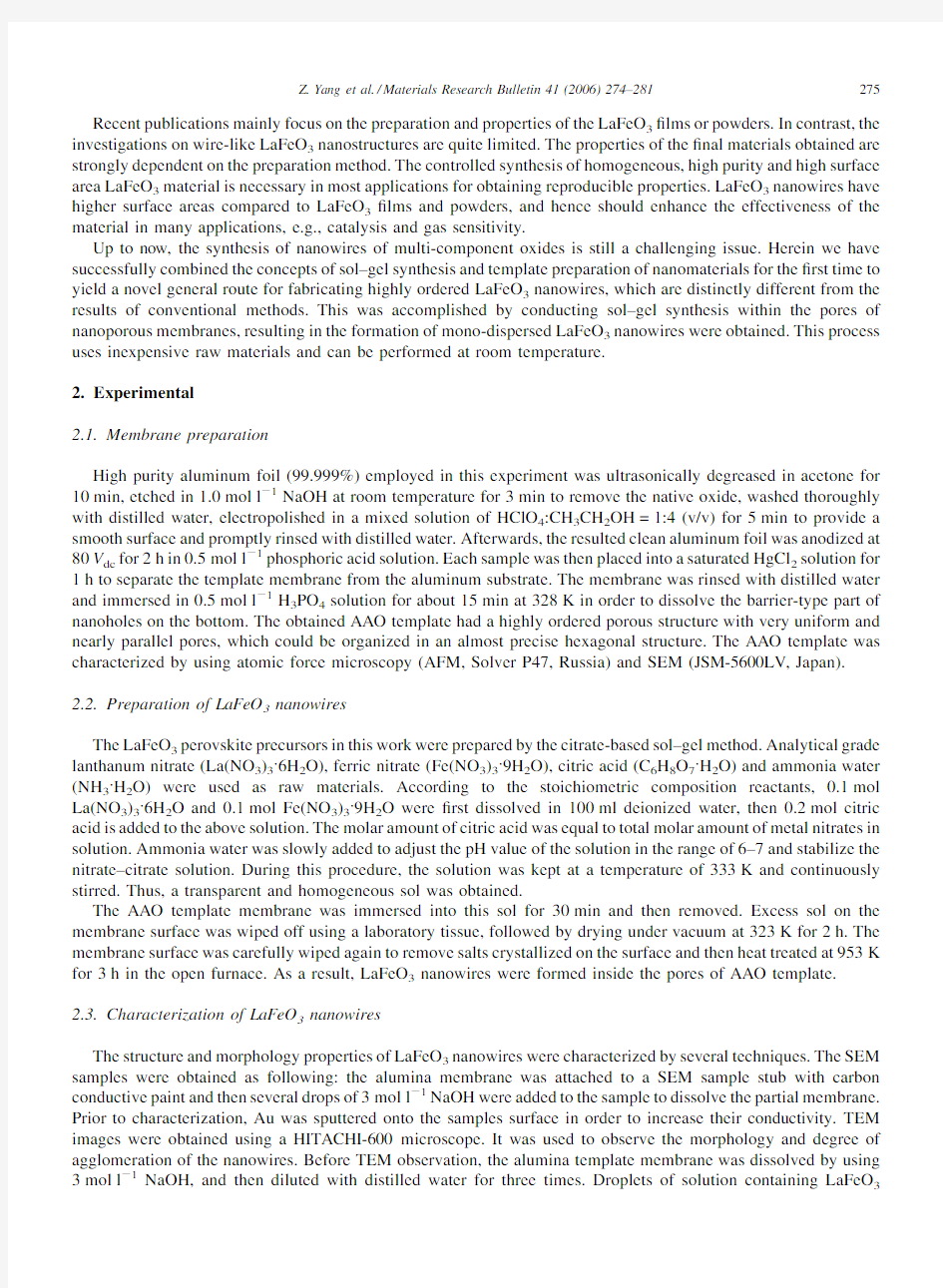
3.1.Characterization of the membrane
When anodized in an acidic electrolyte,aluminum forms a porous oxide with very uniform and parallel pores open at one end and sealed at the other [26–28].Its structure is described as a close-packed array of columnar cells,each containing a central pore of which the size and the interval can be controlled by changing the forming conditions [26–28].As indicated in Fig.1(a),the pores in the membrane are arranged in a regular hexagonal lattice.Perfect hexagonal pore arrays can be observed within domains of microsize,which are separated from neighboring aluminum oxide domains with a different orientation of the pore lattice by grain boundaries.Fig.1(b)depicts the cross-section SEM image of the AAO template with pores parallel to each other and perpendicular to the surface of the membrane.Here,the pores of the membrane are about 100nm in diameter and about 50m m in length with a pore density of about 109–1010cm à2.
3.2.SEM analysis of LaFeO 3nanowires
Fig.2(a–d)shows SEM images of LaFeO 3nanowires grown in AAO template.These photographs show that the nanowires are uniformly distributed,highly ordered,parallel to each other.Few microscopic defects are found in these wires.Fig.2(a)and (b)are planforms from which we can ?nd several clusters of nanowires.The clusters can result from the situation in which the nanowires are uncovered from the framework of the AAO template but freestanding incompletely.When the top alumina of the AAO template is dissolved away,the nanowires embedded in the template release gradually and incline to agglomerate together.It is conceivable that the surface energy of the nanowires causes
Z.Yang et al./Materials Research Bulletin 41(2006)274–281
276Fig.1.(a)AFM image of the surface of AAO template under tapping mode and (b)SEM image of cross-section of AAO template.
277
Z.Yang et al./Materials Research Bulletin41(2006)274–281
this interesting phenomenon.Fig.2(a)and(b)also show that LaFeO3nanowires are abundant,uniform and highly ordered in large area.Fig.2(c)reveals a cross-section where the alumina matrix of the AAO template has been partially dissolved away.It can be seen that the nanowires deposited inside the nanochannel of the AAO template are parallel, tidily aligned and uniformly distributed.It is correlative to that the AAO template had an array of densely parallel nanoholes arranged in a hexagonal fashion.Fig.2(d)shows a split where the alumina matrix of the AAO template has been dissolved away and large quantities of LaFeO3nanowires remain.We can see that these nanowires have a?ber-brush aspect.From these?gures,we?nd that LaFeO3nanowires can be produced in large areas within the pores of the AAO template.At the same time,it also can be estimated that the length of LaFeO3nanowires is about50m m.It is corresponding with the thickness of the AAO template.The outside diameters of these nanowires are about100nm,
which are equivalent to the pore diameter of the template membrane.
Fig.2.SEM images of LaFeO3nanowires with the AAO template partly dissolved:(a,b)top view in low magni?cation and(c,d)cross-section in high magni?cation.
3.3.TEM and SAED analysis of LaFeO 3nanowires
TEM images of LaFeO 3nanowires formed within the AAO template are shown in Fig.3(a)and (b).Fig.3(a)shows several LaFeO 3nanowires,in which some of these nanowires cross and overlap with each other.This image also shows that the diameter of LaFeO 3nanowires is about 100nm,which approximately equals to that of the nanochannels of the AAO template.Although the lengths of nanowires are much less than 50m m,it does not Z.Yang et al./Materials Research Bulletin 41(2006)274–281
278Fig.3.(a)TEM image of several LaFeO 3nanowires after removing AAO;(b)TEM image of one LaFeO 3nanowire and (c)The corresponding selected-area electron diffraction for LaFeO 3nanowires.
imply that the as grown nanowires are really so short,because during the preparation of samples for TEM observation,the nanowires are easily broken by the ultrasonic stirring.These nanowires are uniformly distributed,which indicates that the alumina matrix is dissolved completely.Fig.3(b)shows another image of one LaFeO 3nanowire.It can be seen that the surface of this nanowire is smooth.Fig.3(c)shows the corresponding SAED pattern taken from LaFeO 3nanowires.Lots of individual LaFeO 3nanowires were examined and we always observed diffraction rings.The SAED results indicate that LaFeO 3nanowires are polycrystalline.Generally,the nanowires prepared by the sol–gel method with the AAO templates are polycrystalline [29,30].It should be noted that the diffraction rings are discontinuous and consist of rather sharp spots,which indicates that the nanowires are well crystallized.According to the electron-diffraction formula,the major diffraction spots correspond to the (101),(121),(220),(202),(240),(242)and (204)diffraction planes for LaFeO 3with an orthorhombic perovskite structure.
3.4.XRD analysis of LaFeO 3nanowires
Fig.4shows the XRD patterns of LaFeO 3nanowires after heat treatment at 953K for 3h.The peak positions and their relative intensities are consistent with the standard powder diffraction patterns of perovskite-type LaFeO 3(JCPDS,card number:37–1493).All of the diffraction peaks are assigned to LaFeO 3and no other peaks attributable to La 2O 3and Fe 2O 3are observed.The XRD patterns of LaFeO 3nanowires are characteristic of crystalline perovskite oxides,with an orthorhombic cell,Pnma space group [31].
3.5.XPS analysis of LaFeO 3nanowires
The oxidation state of principal elements of LaFeO 3nanowires in the pores of AAO can be determined by XPS.The binding energies obtained in the XPS analysis are standardized for specimen charging using C 1s as the reference at 284.8eV.Fig.5(a–d)display the XPS spectra of La 3d 5/2,Fe 2p,O 1s and Al 2p core levels for LaFeO 3nanowires embedded in AAO template,respectively.The line of the La 3d 5/2core level has two binding energy peaks located at 839.0and 835.7eV (Fig.5(a)).The peaks located at 709.8and 724.3eV (Fig.5(b))are attributed to the spin–orbit splitting of the Fe (2p)components,Fe 2p 3/2and Fe 2p 1/2,respectively.The line shape of the core levels O 1s and Al 2p are Gaussian-like with a binding energy of 530.7eV (Fig.5(c))and 74.2eV (Fig.5(d)),respectively.We can see that the peak intensities of O 1s and Al 2p are higher than for the other elements.The reason for the weaker peak intensity of La 3d 5/2and Fe 2p derives from the low concentration of LaFeO 3in the AAO template and the LaFeO 3not being covered on the surface of the template.The binding energy values for principal elements of LaFeO 3in the pores of AAO are in good agreement with those of LaFeO 3found in the literature [32,33].XPS spectra further con?rm the main composition of the nanowires in the pores of AAO to be stoichiometric LaFeO 3.
Z.Yang et al./Materials Research Bulletin 41(2006)274–281
279
Fig.4.XRD patterns of LaFeO 3nanowires.
4.Conclusion
In summary,highly ordered LaFeO 3nanowires were successfully fabricated by a citrate-based sol–gel template process.We have also applied SEM,TEM,XRD and XPS techniques to characterize the structure of LaFeO 3nanowires.The SEM and TEM results showed highly ordered LaFeO 3nanowires had a uniform length and diameter,which were determined by the thickness and the pore diameter of the applied AAO template,respectively.XRD patterns indicated that perovskite-type LaFeO 3naowires were orthorhombic symmetry structures.The result of SAED demonstrated that LaFeO 3nanowires were polycrystalline.XPS analysis demonstrated that the stoichiometric LaFeO 3nanowires were formed.We have succeeded in providing a meaningful method to design perovskite-type complex oxide LaFeO 3nanowires.It could be expected that the novel and effective technique presented in this article would be also appropriate for the preparation of nanowires of other monocomponent or multi-component oxides.This facile method of preparing highly ordered LaFeO 3nanowires with a large area might be important for many applications in nanomaterials.
Acknowledgments
This work is supported by the National Natural Science Foundation of China (No.60171004).The authors would like to express our sincere thanks to Researcher Jia-Zheng Zhao of Lanzhou Institute of Chemical Physics of the Chinese Academy of Sciences for SEM measurement,to Chief Engineer Da-Kang Song of Material Department of Lanzhou University for measurement and analysis of XRD data.
Z.Yang et al./Materials Research Bulletin 41(2006)274–281
280
Z.Yang et al./Materials Research Bulletin41(2006)274–281281 References
[1]Y.K.Zhou,H.L.Li,J.Mater.Chem.12(2002)681.
[2]Y.K.Zhou,J.E.Huang,H.L.Li,Appl.Phys.A:Mater.Sci.Process.76(2003)53.
[3]Y.K.Zhou,C.M.Shen,H.L.Li,Solid State Ionics146(2002)81.
[4]A.D.Paoli,A.A.Barresi,Ind.Eng.Chem.Res.40(2001)1460.
[5]G.Martinelli,M.C.Carotta,M.Ferroni,Y.Sadaoka,E.Traversa,Sens.Actuators B55(1999)99.
[6]N.Q.Mih,J.Am.Ceram.Soc.76(1993)563.
[7]T.Inoue,N.Seki,K.Eguchi,H.Arai,J.Electrochem.Soc.137(1990)2523.
[8]H.Tanaka,T.Kawai,Solid State Commun.112(1999)201.
[9]J.P.Lukaszewicz,Sens.Actuators B4(1991)227.
[10]S.Q.Zhao,J.K.O.Sin,B.K.Xu,M.Y.Zhao,Z.Y.Peng,H.Cai,Sens.Actuators B64(2000)83.
[11]X.Ge,Y.Liu,X.Liu,Sens.Actuators B79(2001)171.
[12]T.Arakawa,H.Kurachi,J.Shiokawa,J.Mater.Sci.4(1985)1207.
[13]Y.Takahashi,H.Taguchi,J.Mater.Sci.Lett.3(1984)251.
[14]N.N.Toan,S.Saukko,https://www.360docs.net/doc/a318245047.html,ntto,Physica B327(2003)279.
[15]Y.Matsuura,S.Matsushima,M.Sakamoto,Y.Sadaoka,J.Mater.Chem.3(1993)767.
[16]M.Kakihana,J.Sol–gel Sci.Technol.6(1996)7.
[17]Q.W.Zhang,F.Saito,J.Mater.Sci.36(2001)2287.
[18]C.Va′zquez-Va′zquez,P.Ko¨gerler,M.A.Lo′pez-Quintela,R.D.Sa′nchez,J.Rivas,J.Mater.Res.13(1998)451.
[19]X.W.Qi,J.Zhou,Z.X.Yue,Z.L.Gui,L.T.Li,Ceram.Int.29(2003)347.
[20]W.J.Zheng,R.H.Liu,D.K.Peng,G.Y.Meng,Mater.Lett.43(2000)19.
[21]M.Sivakumar,A.Gedanken,W.Zhong,Y.H.Jiang,Y.W.Du,I.Brukental,D.Bhattacharya,Y.Yeshurun,I.Nowik,J.Mater.Chem.14(2004)
764.
[22]Y.Sadaoka,H.Aono,E.Traversa,M.Sakamoto,J.Alloys Compd.278(1998)135.
[23]J.J.Liang,H.S.Weng,Ind.Eng.Chem.Res.32(1993)2563.
[24]M.Popa,J.Frantti,M.Kakihana,Solid State Ionics154–155(2002)437.
[25]A.E.Giannakas,https://www.360docs.net/doc/a318245047.html,davos,P.J.Pomonis,Appl.Catal.B49(2004)147.
[26]Y.Peng,H.L.Zhang,S.L.Pan,H.L.Li,J.Appl.Phys.87(2000)7405.
[27]S.L.Pan,H.L.Zhang,Y.Peng,Z.Wang,H.L.Li,Chem.J.Chin.Univ.20(1999)1622.
[28]C.A.Huber,T.E.Huber,M.Sadoqi,J.A.Lubin,S.Manalis,C.B.Prater,Science263(1994)800.
[29]Y.Lin,F.Q.Sun,X.Y.Yuan,B.Y.Geng,L.D.Zhang,Appl.Phys.A:Mater.Sci.Process.78(2003)1197.
[30]B.A.Hernandez,K.S.Chang,E.R.Fisher,P.K.Dorhout,Chem.Mater.14(2002)480.
[31]P.Ciambelli,S.Cimino,L.Lisi,M.Faticanti,G.Minelli,I.Pettiti,P.Porta,Appl.Catal.B33(2001)193.
[32]X.Li,H.B.Zhang,X.X.Liu,S.J.Li,M.Y.Zhao,Mater.Chem.Phys.38(1994)355.
[33]X.Li,X.X.Liu,B.Xu,M.Y.Zhao,J.Alloys Compd.186(1992)315.