CAT320DL液压挖掘机

320D L
?Hydraulic Excavator
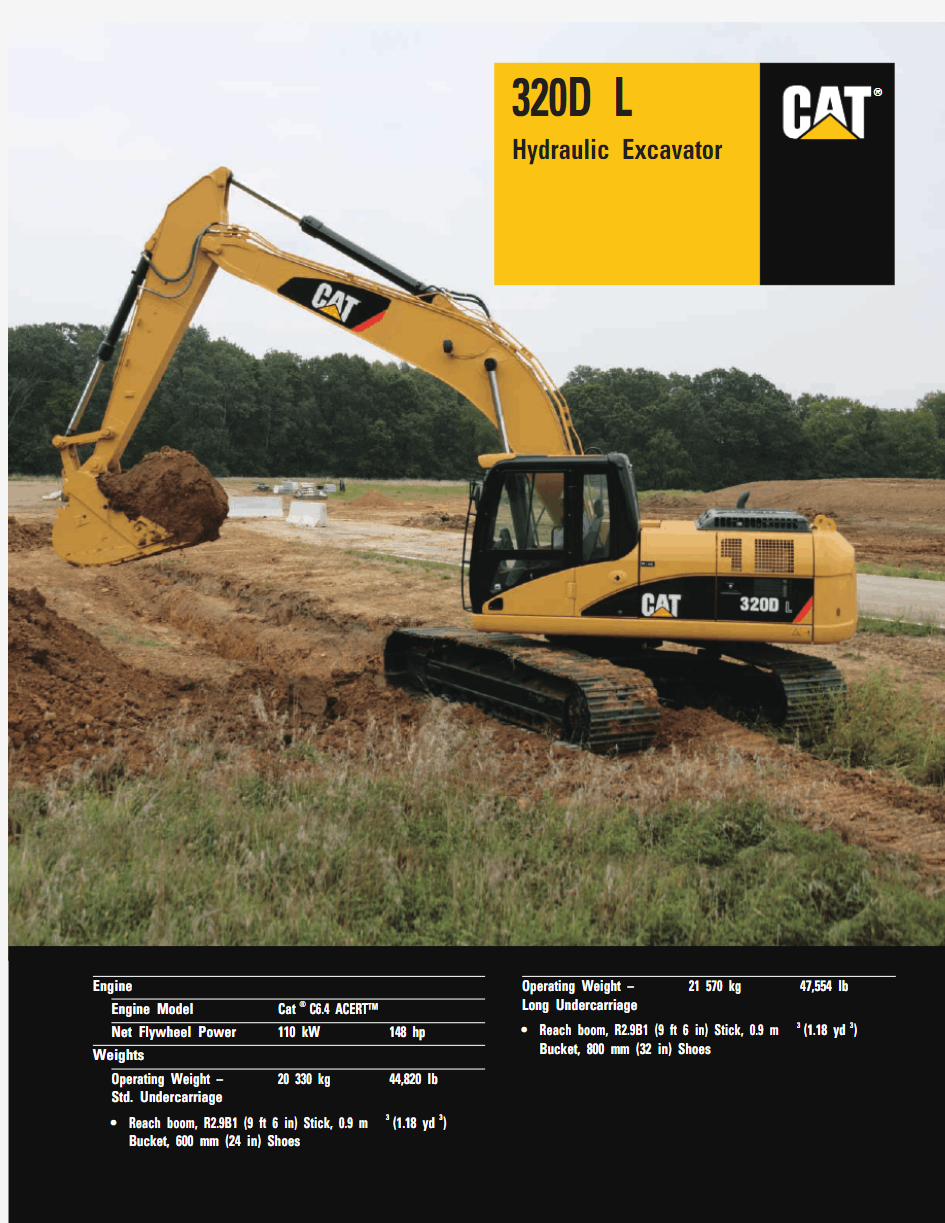
320D L Hydraulic Excavator
The D Series incorporates innovations for improved performance and versatility.
it
got
operating costs.
Service and Maintenance
Fast, easy service has been designed
with extended service intervals,
advanced filtration, convenient filter
access and user-friendly electronic
diagnostics for increased productivity and reduced maintenance costs. pg. 12?
Versatility
Caterpillar offers a wide variety of factory-installed attachments that enhance performance and job site management.pg. 11
Operator Comfort
Provides maximum space, wider
visibility and easy access to switches.
The monitor is a full-color graphical
display that allows the operator to
understand the machine information
easily. Overall, the new cab provides
a comfortable environment for the
operator.pg. 6
?
Hydraulics
The hydraulic system has been designed
to provide reliability and outstanding
controllability. An optional Tool
Control System provides enhanced
flexibility.pg. 5
C6.4 with ACERT? Technology
ACERT?Technology works at the
point of combustion to optimize engine performance and provide low exhaust
emissions to meet U.S. EPA Tier 3
emission regulations, with exceptional performance capabilities and proven
reliability.pg. 4
?
2
?New Feature
3
Complete Customer Support
Your Cat ?dealer offers a wide range of services that can be set up under a customer support agreement when you purchase your equipment. The dealer will help you choose a plan that can cover everything from machine
configuration to eventual replacement.pg. 13
Work Tools – Attachments
A variety of work tools, including
buckets, couplers, hammers, and shears are available through Cat ?Work Tools.pg. 10
?Booms, Sticks and Bucket Linkages The bucket linkage pins on the mass excavation configuration have been enlarged to improve reliability and durability.pg. 9
Structures
Caterpillar ?design and manufacturing techniques assure outstanding durability and service life from these important components.pg. 8
Cat C6.4.The Cat C6.4 with ACERT?Technology introduces a series of
evolutionary, incremental improvements that provide breakthrough engine technology. The building blocks of ACERT Technology are fuel delivery,air management and electronic control.ACERT Technology optimizes engine performance while meeting U.S. EPA Tier 3 emission regulations. With its proven technology, robust components and precision manufacturing, you can count on this engine to power up at start time and keep working productively all shift long.
Performance.The 320D, equipped with the C6.4 engine with ACERT?Technology, provides 7 percent more power as compared to the 3066TA in the 320C L. The additional power delivers a speed and efficiency advantage in high production applications.
Automatic Engine Speed Control.The two-stage, one-touch control
maximizes fuel efficiency and reduces sound levels.
ADEM? A4 Engine Controller.The ADEM A4 electronic control
module manages fuel delivery to get the best performance per liter of fuel used.The engine management system provides flexible fuel mapping, allowing the engine to respond quickly to varying application needs. It tracks engine and machine conditions while keeping the engine operating at peak efficiency.
Electronic Control Module.
The Electronic Control Module (ECM)works as the “brain” of the engine’s control system, responding quickly to operating variables to maximize engine efficiency. Fully integrated with sensors in the engine’s fuel, air, coolant, and exhaust systems, the ECM stores and relays information on conditions such as rpm, fuel consumption, and diagnostic information.
Fuel Delivery.The Cat C6.4 features electronic controls that govern the fuel injection system. Multiple injection fuel delivery involves a high degree of precision. Precisely shaping the combustion cycle lowers combustion chamber temperatures, generating fewer emissions and optimizing fuel combustion. This translates into more work output for your fuel cost.Cooling System.The cooling fan is directly driven from the engine.
An electrically controlled viscous clutch fan is available as an attachment to reduce fan noise. The optimum fan speed is calculated based on the target engine speed, coolant temperature, hydraulic oil temperature and actual fan speed.When fan speed is reduced, there’s more power available for other functions –
and less fuel is burned.
4
C6.4 with ACERT? Technology
The Cat ?C6.4 gives the 320D exceptional power and fuel efficiency unmatched in the
industry for consistently high performance in all applications.
Component Layout.To optimize efficiency of hydraulic performance, the hydraulic components are located close together, which reduces friction loss and pressure drops in the lines. System Pressure.System pressure has been increased to 35,000 kPa (5,076psi), which attributes to improved performance:
?Increased stick and bucket forces (up 7 percent higher than the 320C)
to better handle those tight digging
conditions
?More drawbar pull (206 kN –
46,322lb) to provide more ability
to climb slopes, easier spot turns and improved travel in poor underfoot
conditions
?More lift capacity, generally over the front where you are generally
hydraulically limited
Heavy Lift.The 320D features the addition of a heavy lift, which increases system pressure to 36,000 kPa (5,220psi), giving even more lift capacity over
the front. Heavy Lift is activated be depressing the soft switch on the right hand console. As the pressure increases, the engine speed is reduced, which allows better control while lifting objects. Pilot System.The pilot pump is independent from the main pumps and controls the front linkage, swing and travel operations.Hydraulic Cross Sensing System.
The hydraulic cross sensing system
utilizes each of two hydraulic pumps to
100 percent of engine power, under all
operating conditions. This improves
productivity with faster implement
speeds and quicker, stronger pivot turns.
Boom and Stick Regeneration Circuit.
Boom and stick regeneration circuit
saves energy during boom-down and
stick-in operation which increases
efficiency, reduces cycle times and
pressure loss for higher productivity,
lower operating costs and increased
fuel efficiency.
Auxiliary Hydraulic Valve.The auxiliary
valve is standard on the 320D. Control
Circuits are available as attachments,
allowing for operation of high and
medium pressure tools such as shears,
grapples, hammers, pulverizers,
multi-processors and vibratory plate
compactors.
Hydraulic Cylinder Snubbers.Snubbers
are located at the rod-end of the boom
cylinders and both ends of the stick
cylinders to cushion shocks while
reducing sound levels and extending
component life.
5
Hydraulics
Cat?
hydraulics deliver power and precise control to keep material moving.
Operator Comfort
Caterpillar offers the most intuitive and easy to operate excavators while providing great all around visibility and exceptional operator comfort.
6
Operator Station.The layout of the interior has been redesigned to maximize operator comfort and reduce operator fatigue.?Frequently used switches have been relocated for easier access.?Consoles and armrests have been redesigned for better comfort and
adjustability.
?More seat options – choose from the standard mechanical suspension
seat, or the optional air suspension
seat with heater. Both provide
excellent comfort.
Standard Cab Equipment.To enhance operator comfort and productivity,
the cab includes a lighter, drink holder, coat hook, service meter, literature holder, magazine rack and storage compartment.
Joystick Control.Joystick controls have low lever effort and are designed to
match the operator’s natural wrist and arm position.
Hydraulic Activation Control Lever. For added safety, this lever must be
in the operate position to activate the machine control functions. Automatic Climate Control.Fully automatic climate control adjusts temperature and flow, and determines which air outlet is best in each situation with a touch of a button.
Cab Exterior.The exterior design uses thick steel tubing along the bottom perimeter of the cab, improving the resistance of fatigue and vibration. Cab Mounts.The cab shell is attached to the frame with viscous rubber cab mounts, which dampen vibrations
and sound levels while enhancing operator comfort.Windows.All glass is affixed directly
to the cab for excellent visibility
eliminating window frames.
Wipers.Pillar-mounted wipers increase
the operator’s viewing area and offer
continuous and intermittent modes.
Skylight.An enlarged skylight with
sunshade provides excellent visibility
and ventilation.
Monitor.The monitor is a full color
Liquid Crystal Display that gives
you vital operating and performance
information, alerts in text, all in a
simple, east to navigate format.
Default Display.Three analog gauges,
fuel level, hydraulic oil temperature
and coolant temperature, are displayed
in this area.
Main Menu.Four menu options to
choose from:
Settings – Adjust monitor settings,
select work tool or choose video
mode(when equipped with a camera)
Maintenance – Displays service intervals
and hours accumulated since last serviced.
Performance – Displays machine
performance attributes such as Engine
Speed, Coolant and Hydraulic Oil
Temperature.
Service – Allows access to machine
parameters for service intervals,
diagnostic information and information
related to the machines software.
Event Display.Machine information
is displayed in this area with the icon
and language.
Multi-information Display.This area
is reserved for displaying various
information which is convenient for the
operator. The “CAT” logo is displayed
when no information is available to be
displayed.
7
Robust Undercarriage.A solid
foundation built tough to absorb the stresses of everyday work.?Rollers and idlers are sealed and lubricated to extend service life.?
Track links are assembled and sealed with grease to decrease internal bushing wear and increase life by as much as 25 percent, when
compared to dry seal undercarriages.?
Spring recoil system stroke has been increased to better relieve excess track tension, which can occur when material builds up between the track and sprocket.
Undercarriage Options.Choose the undercarriage option that best matches your application.?
Standard undercarriage – Works well in restricted work spaces and on uneven, rocky terrain. It’s also preferred on jobs that require frequent repositioning of the machine.?
Long undercarriage – Allows for maximum stability and lift capacity.
Rugged Structures.Structural components and the undercarriage are the backbone of the machine’s durability. Caterpillar places a lot of emphasis on the machine’s durability during the designing and manufacturing of its excavators.?
Up to 95 percent of the structural welds are welded by robots, which achieve up to three times the penetration of a manual weld and improving overall durability of the machine.
?
The 320D’s main frame utilizes high-tensile strength steel and a one-piece swing table, which improves strength and reliability.?
The carbody has a X-shaped, box section design to resist bending and twisting forces.
?
Track roller frames are press-formed in a pentagonal shape for additional strength.
8
Structures
320D is designed to handle the most rugged operating conditions, while providing long life
and value.
Front Linkage Options.The Reach Boom allows excellent all-around versatility and a large working
envelope. It can be equipped with the following three sticks:?R3.9B1 – offers maximum reach and digging depth
?R2.9B1 – performs well in a mid-range working envelope ?
R2.5B1 – a good match when the job requires a larger bucket or a hammer
Mass Excavation Boom is designed for heavy-duty, high production earthmoving applications and has a single system-matched stick ?
M2.4CB2 – delivers significantly higher digging forces and allows the use of large buckets.
Super Long Reach Front – with reaches up to 15.2 m (50 ft) this configuration is designed for light duty applications requiring an extra large working envelope.
Linkage Pins.The bucket linkage pins for the Mass Excavator configuration have been enlarged to improve reliability and durability. All the pins in the front linkages have thick chrome plating,giving them high wear and corrosion resistance.
Bucket Linkage.The power link improves durability, increases machine-lifting capability in key lifting positions and with the integrated lift-eye it is easier to use than compared to the previous power link. The lift eye also gives you the optimum lift performance. It allows you to lower the load point, which
maximizes the use of the boom cylinders.
9
Booms, Sticks and Bucket Linkages
Built for Performance and long service life, Caterpillar ?booms and sticks are large, welded,
box-section structures with thick, multi-plate fabrications in high stress areas.
Wide Variety of Work Tools.Caterpillar offers a complete line of work tools to match all of your application needs:?Hammers – matched to Cat
machines for optimum performance ?
Thumbs, Stiff Link, Full Rotation –transforms your 320D into a
versatile material handling machine ?
Grapples – choose from a large variety of grapples that best suit your application
?
Multi-processors – does the work of many types of demolition tools by use of interchangeable jaws ?
Shears – features 360 degree rotation and high force to weight ratio
?Pulverizers – ideally suited for rapid,non-explosive demolition applications ?
Vibratory Plate Compactors –
provide superior compaction force in a reliable, low maintenance package ?
Rippers – perfectly suited for
trenching and pipeline applications where conditions aren’t favorable to traditional ripping methods
Caterpillar Buckets.The most expansive choice of buckets that can optimize machine performance and match your application needs.
?
General Purpose Buckets – for digging in low impact, moderately abrasive materials such as dirt, loam,gravel and clay.
?
Heavy-Duty Buckets – for use in abrasive applications such as mixed dirt, clay and rock.
?
Heavy-Duty power Buckets – for use in abrasive applications where breakout force and cycle times are critical – good for materials such as mixed dirt, clay and rock.?
Ditch Cleaning Buckets – wide and shallow for ditch cleaning, bank forming and finishing.
Caterpillar Ground Engaging Tools (GET).Choose from a wide variety of tips that maximize bucket and machine performance. Sidecutters and sidebar protectors are also available.
Pin Grabber Plus Hydraulic Pin Grabber
Couplers.Multiply the versatility and utility of 320D.?
Hydraulic Pin Grabber Plus – allows quick and easy tool changes without having to leave the cab. Picks up a large variety of tools equipped with standard pins.
?
Dedicated Coupler – no loss of tip radius, maximizing the breakout
forces on your 320D.
10
Work Tools – Attachments
The 320D has an extensive selection of work tools to optimize machine performance.
Auxiliary Hydraulic Options.Allows you to configure your 320D to meet your work tools needs, while increasing its versatility.?
Single Function Circuit – suited for tools that require one-way flow with both pumps, such as hammers,vibratory plate compactors.?
Double Function Circuit – suited for tools that require two-way flow,utilizing one pump, such as thumbs or non-rotation grapples or shears.?
Tool Control System –
accommodates single or double function tools, as well as rotating tools when equipped with medium pressure.
— Stores pressure and flow
information for up to 10 tools — Cat tools selectable that have preset flows and pressures — Shortcut button on right hand
console, making tool selection easier.
Machine Security.An optional Machine Security System is available from the factory on the 320D. This system controls when the machine can be operated and utilizes specific keys to prevent unauthorized machine use, a significant theft deterrent.
More Attachments.The 320D offers the most options available to equip your 320D to best match your application and work environment requirements.From track shoe size to guarding packages to operator comfort options,the 320D offers more options.
Product Link.Both the PL121 and
PL321 are available as factory installed attachments.
PL121 gives you Asset Watch, which includes the following features:?Engine hours ?Machine location
?Time based fences (when the machines can operate)
?
Geo-based fences (boundaries that the machine can operate)
PL321 gives you all of the features listed for PL121, plus the ability to
include Health and Maintenance Watch.?
Health Watch °Codes from on-board EDM’s/Sensors
°Estimated Fuel Consumption °Fuel Watch ?
Maintenance Watch
°Preventative Maintenance Planning °Preventative Maintenance Checklists °Overdue PM Notification °
PM History Recording
11
Versatility
A wide variety of optional factory-installed attachments are available to enhance
performance and improve job site management.
Ground Level Service.The design and layout of the 320D was made with the service technician in mind. Many service locations are easily accessible at ground level allowing critical maintenance to get done quickly and efficiently.Air Filter Compartment.The air filter features a double-element construction for superior cleaning efficiency.
When the air cleaner plugs, a warning is displayed on the monitor screen inside the cab.
Pump Compartment.A service door on the right side allows for ground level access to the hydraulic pump, engine oil filter, case drain and pilot filters.
Radiator Compartment.The air
conditioning condenser swings out to allow access to the engine radiator and oil cooler. The air to air after cooler is fixed in position above the condenser.Greasing Points.A concentrated remote greasing block on the boom delivers grease to hard-to-reach locations on the front.
Capsule Filter.The hydraulic return filter, a capsule filter, is situated outside the hydraulic tank. This filter prevents contaminants from entering the system when hydraulic oil is changed and keeps the operation clean.
Anti-Skid Plate.Anti-skid plate covers top of storage box and upper structure to prevent slipping during maintenance.
Diagnostics and Monitoring.The 320D
is equipped with S?O?S SM
sampling ports and hydraulic test ports for the hydraulic system, engine oil, and for coolant. A test connection for the Cat Electronic Technician (Cat ET)service tool is located in the cab.Extended Service Interval.320D service and maintenance intervals have been extended to reduce machine service
time and increase machine availability.
12
Service and Maintenance
Simplified service and maintenance features save you time and money.
Product Support.You will find nearly all parts at our dealer parts counter. Cat dealers utilize a worldwide computer network to find in-stock parts to minimize machine down time. Save money with remanufactured components. Machine Selection.Make detailed comparisons of the machines you are considering before you buy. What are the job requirements, machine attachments and operating hours? What production is needed? Your Cat dealer can provide recommendations.Customer Support Agreements.
Cat dealers offer a variety of product
support agreements, and work with
customers to develop a plan the best
meets specific needs. These plans can
cover the entire machine, including
attachments, to help protect the
customer’s investment.
Operation.Improving operating
techniques can boost your profits.
Your Cat dealer has videotapes, literature
and other ideas to help you increase
productivity, and Caterpillar offers
certified operator training classes to
help maximize the return on your
investment.
Maintenance Services.Repair option
programs guarantee the cost of repairs
up front. Diagnostic programs such
as Scheduled Oil Sampling, Coolant
Sampling and Technical Analysis help
you avoid unscheduled repairs.
Replacement.Repair, rebuild, or replace?
Your Cat dealer can help you evaluate
the cost involved so you can make the
right choice.
https://www.360docs.net/doc/a118820095.html,?.
13
Complete Customer Support
Cat?
dealer services help you operate longer with lower costs.
14320D L Hydraulic Excavator specifications
Drive
Maximum Drawbar Pull
205 kN 46,311 lb Maximum Travel Speed
5.5 kph
3.4 mph
Hydraulic System
Main Implement System – 205 L/min 54 gal/min Maximum Flow (2x)
Max. pressure – Equipment 35 000 kPa 5,076 psi Max. pressure – Equipment – 35 000 kPa 5,076 psi Heavy
Max. pressure – Travel 35 000 kPa 5,076 psi Max. pressure – Swing
24 500 kPa 3,553 psi Pilot System – Maximum flow 32.4 L/min 9 gal/min Pilot System – Maximum pressure 3900 kPa 566 psi Boom Cylinder – Bore 120 mm 4.7 in Boom Cylinder – Stroke 1260 mm 49.6 in Reach Stick Cylinder – Bore 140 mm 5.5 in Mass Stick Cylinder – Bore 140 mm 5.5 in Reach Stick Cylinder – Stroke 1518 mm 59.8 in Mass Stick Cylinder – Stroke 1504 mm 59.2 in B1 Family Bucket Cylinder – 120 mm 4.7 in Bore
B1 Family Bucket Cylinder – 1104 mm 43.5 in Stroke
CB2 Family Bucket Cylinder – 135 mm 5.3 in Bore
CB2 Family Bucket Cylinder – 1156 mm
45.5 in
Stroke
Sound Performance
Performance
ANSI/SAE J1166 APR 90
?When properly installed and maintained, the cab offered by Caterpillar, when tested with doors and windows closed according to ANSI/SAE J1166 OCT 98, meets OSHA and MSHA requirements for operator sound exposure limits in effect at time of manufacture.
?Hearing protection may be needed when operating with an open operator station and cab (when not properly maintained or doors/windows open) for extended periods or in noisy environment.
Standards
Brakes SAE J1026 APR90Cab/FOGS
SAE J1356 FEB88
Engine
Engine Model
Cat C6.4 ACERT? Net Flywheel Power 110 kW 148 hp Net Power – ISO 9249110 kW 148 hp Net Power – SAE J1349110 kW 148 hp Net Power – EEC 80/1269110 kW 148 hp Bore 102 mm 4.02 in Stroke
130 mm 5.12 in Displacement
6.4 L 389 in ?The 320D meets U.S. EPA Tier 3 emissions requirements.?Net flywheel power advertised is the power available at the flywheel when the engine is equipped with fan, air cleaner,muffler and alternator.
?No engine power derated below 2300 m (7,500 ft).
Weights
Operating Weight – 20 330 kg
44,820 lb
Std. Undercarriage
?Reach boom, R2.9B1 (9 ft 6 in) Stick, 0.9 m 3(1.18 yd 3
) Bucket,600 mm (24 in) Shoes
Operating Weight – 21 570 kg
47,554 lb
Long Undercarriage
?Reach boom, R2.9B1 (9 ft 6 in) Stick, 0.9 m 3
(1.18 yd 3
) Bucket,800 mm (32 in) Shoes
Service Refill Capacities
Fuel Tank Capacity 410 L 108 gal Cooling System 25 L 6.6 gal Engine Oil 30 L 8 gal Swing Drive
8 L 2.1 gal Final Drive (each)
8 L 2.1 gal Hydraulic System (including tank)260 L 69 gal Hydraulic Tank
120 L 32 gal Hydraulic Tank (Including 138 L
36 gal
suction pipe)
Swing Mechanism
Swing Speed 11.5 rpm Swing Torque
61.8 kN·m
45,612 lb ft
15
320D L Hydraulic Excavator
specifications
Boom Options Reach Reach Reach Mass Super Long Reach 5.68 (18'7")
5.68 (18'7") 5.68 (18'7") 5.2 m (17'1")8.85 m (29'1")Stick Options R2.9B1 m (9'7")R2.5B1 m (8'2")
R3.9B1 m (12'8")Std/SA Std/SA M2.4CB2 m (7'10") 6.28 m (20'7")1Shipping Height 3740 mm (12'3")3030 mm (9'11")3050 mm (10'0")3280 mm (10'9")3190 mm (10'6")2Shipping Length 9440 mm (31'0")9460 mm (31'0")9460 mm (31'0")9050 mm (29'8")12 680 mm (41'7")3Tail Swing Radius
2750 mm (9'0")2750 mm (9'0")2750 mm (9'0")2750 mm (9'0")
2750 mm (9'0")
4
Length to Center of Rollers Standard 3265 mm (10'9")3265 mm (10'9")3265 mm (10'9")3265 mm (10'9")n/a
Long
3650 mm (12'0")3650 mm (12'0")3650 mm (12'0")3650 mm (12'0")3650 mm (12'0")5Track Length
Standard 4075 mm (13'4")4075 mm (13'4")4075 mm (13'4")4075 mm (13'4")n/a
Long
4455 mm (14'7")4455 mm (14'7")4455 mm (14'7")4455 mm (14'7")4455 mm (14'7")6Ground Clearance 450 mm (1'6")450 mm (1'6")450 mm (1'6")450 mm (1'6")450 mm (1'6")7Track Gauge
Standard 2200 mm (7'3")2200 mm (7'3")2200 mm (7'3")2200 mm (7'3")n/a
Long
2380 mm (7'10")2380 mm (7'10")2380 mm (7'10")2380 mm (7'10")2380 mm (7'10")8Transport Width
800 mm Shoes 700 mm Shoes 600 mm Shoes 800 mm Shoes Standard 3000 mm (9'10")2900 mm (9'6")2800 mm (9'2")2800 mm (9'2")2800 mm (9'2")Long 3180 mm (10'5")3080 mm (10'1")2980 mm (9'9")2980 mm (9'9")2980 mm (9'9")9Cab Height
2950 mm (9'8")2950 mm (9'8")2950 mm (9'8")2950 mm (9'8")2950 mm (9'8")10Counterweight Clearance
1020 mm (3'4")1020 mm (3'4")1020 mm (3'4")1020 mm (3'4")1020 mm (3'4")
* Removing the bucket and quick coupler changes the shipping height to 3390 mm (11'1").
Dimensions
All dimensions are approximate.
16
320D L Hydraulic Excavator specifications
Reach Excavator Working Ranges
Reach (R) boom configuration
Boom Options Reach Reach Reach Reach Reach 5.68 m (18'7") 5.68 m (18'7") 5.68 m (18'7") 5.68 m (18'7") 5.68 m (18'7")Stick Options R3.9B1 m (12'8")R2.9B1 m (9'7")R2.5B1 m (8'2")R2.9B1 m (9'7")R2.5B1 m (8'2")Bucket
1.0 m 3(1.31 yd 3) 1.0 m 3(1.31 yd 3) 1.0 m 3(1.31 yd 3)
Pin Grabber Pin Grabber
Quick Quick Coupler with Coupler with
1.0 m 3(1.31 yd 3
) 1.0 m 3(1.31 yd 3)
1Maximum Digging Depth 7660 mm (25'2")6720 mm (22'1")6300 mm (20'8")6980 mm (22'11")6560 mm (21'6")2Maximum Reach at 10 760 mm (35'4")9860 mm (32'4")9460 mm (31'0")10 120 mm (33'2")9730 mm (31'11")Ground Level
3Maximum Cutting Height 9940 mm (32'7")9490 mm (31'2")9290 mm (30'6")9720 mm (31'11")9520 mm (31'0")4Maximum Loading Height 6940 mm (22'9")6490 mm (21'4")6290 mm (20'8")6230 mm (20'5")6030 mm (19'9")5Minimum Loading Height 1230 mm (4'0")2170 mm (7'1")2590 mm (8'6")1910 mm (6'3")2330 mm (7'8")6Maximum Depth Cut for 7270 mm (23'10")
6370 mm (20'11")
5950 mm (19'6")5680 mm (18'8")5290 mm (17'4")
2440 m (8') Level Bottom 7
Maximum Vertical Wall 6970 mm (22'10")6060 mm (19'11")5650 mm (18'6")5380 mm (17'8")4990 mm (16'4")
Digging Depth
All measurements are approximate
01234567891011105
10
15
20
25
30
35
01234
5678910678
5432115102025
5051015
20253035Meters
Feet
Meters
Feet 01
234
5678910678
54321
15102025
50
5
1015
20
253035
Meters
Feet 0123456789101110
5
10
15
20
25
30
35
Meters
Feet
2
3
17
6
4
5
2
3
1
76
4
5 2.9 m (9'7")2.5 m (8'2")Pin Grabber Pin Grabber
17
320D L Hydraulic Excavator specifications
Mass Excavator Working Ranges
Mass (M) boom configuration
Reach Excavator Working Ranges
Reach (R) boom configuration
Boom Options
Mass Super Long Reach 5.2 m (17'1")8.85 m (29'1")Stick Options M2.4CB2 m (7'10") 6.28 m (20'7")Bucket
1.35 m 3(1.77 yd 3)0.46 m 3(0.80 yd 3)1Maximum Digging Depth
5890 mm (19'4")11 740 mm (38'6")2Maximum Reach at Ground Level 8960 mm (29'5")15 590 mm (51'2")3Maximum Cutting Height 8930 mm (29'4")13 240 mm (43'5")4Maximum Loading Height 5720 mm (18'9")11 150 mm (36'7")5Minimum Loading Height 2230 mm (7'4")2100 mm (6'11")
6Maximum Depth Cut for 5660 mm (18'7")—2440 m (8') Level Bottom
7Maximum Vertical Wall Digging Depth
5360 mm (17'7")
11 300 mm (37'1")
All measurements are approximate
Meters
Feet 012345678910111Meters
Feet
5
10
15
20
25
30
35
01234
5678910678
54321s
15102025
5051015
20253035
Meter Feet 2
3
1
7
6
4
53
17
2
54
320D Bucket and Stick Forces
General Purpose Buckets
Stick R3.9B1R2.9B1R2.9B1 w/Coupler R2.5B1R2.5B1 w/Coupler M2.4CB2
kN lb kN lb kN lb kN lb kN lb kN lb Bucket Digging Force (ISO)14031,36114031,36111626,14514031,36111626,14517539,319 Stick Digging Force (ISO)8920,09810623,89710022,43611826,46011024,70612728,438 Bucket Digging Force (SAE)12528,07912528,07910824,18912528,07910824,18915835,452 Stick Digging Force (SAE)8719,64810323,2239822,00911425,62810724,14412327,539
Power Buckets
Stick R3.9B1R2.9B1R2.9B1 w/Coupler R2.5B1R2.5B1 w/Coupler M2.4CB2
kN lb kN lb kN lb kN lb kN lb kN lb Bucket Digging Force (ISO)16336,71116336,71112427,80916336,71112427,80919644,040 Stick Digging Force (ISO)9120,50310924,48210222,86312127,20211225,22413029,180 Bucket Digging Force (SAE)14432,41714432,41711325,49314432,41711325,49317238,645 Stick Digging Force (SAE)8919,96310623,7179922,30111726,23510924,52712528,034
Heavy Duty/Rock Buckets
Stick R3.9B1R2.9B1R2.9B1 w/Coupler R2.5B1R2.5B1 w/Coupler M2.4CB2
kN lb kN lb kN lb kN lb kN lb kN lb Bucket Digging Force (ISO)14031,56314031,56311726,25814031,56311726,25817539,319 Stick Digging Force (ISO)9020,12010623,92010022,45811826,50511024,72912728,438 Bucket Digging Force (SAE)12528,07912528,07910724,14412528,07910824,21215534,800 Stick Digging Force (SAE)8719,62610323,2009821,96411425,60610724,10012227,359
Major Component Weights
kg lb Base machine with counterweight (without front linkage)STD undercarriage with 600 mm shoe16 26035,847
L undercarriage with 800 mm shoe17 47038,515 Two boom cylinders (Each)182401 Counterweight
Standard38608,510 Super Long Reach483010,648 Boom (includes lines, pins and stick cylinder)
Reach boom 5.7 m (18'5")16403,616 Mass boom 5.2 m (17'1")16703,682 Super Long Reach Boom – 8.85 m (29'1")21804,806 Stick (includes lines, pins, bucket cylinder and linkage)
R3.9 (12'8")10632,344 R2.9 (9'7")8181,803 R2.5 (8'2")7791,717 M2.4 (7'10")9852,172 Super Long Reach Stick – 6.82 m (20'7")16003,527 Undercarriage [includes Carbody, Swing bearing, STD undercarriage with 600 mm shoe667014,705 Track frame, Rollers, Idlers, Steps, Guards, Final drive]L undercarriage with 800 mm shoe788017,372 18320D L Hydraulic Excavator specifications
19
320D L Hydraulic Excavator specifications
320D L Bucket Specifications and Compatibility
Adapter Capacity*
Width
Tip Radius
Weight
Teeth
Reach Boom Stick
Mass (w/o tips)Boom
R2.9B1
R2.5B1Stick m
3
yd
3
mm
in
mm
in
kg
lb
Qty
R3.9B1R2.9B1w/QC R2.5B1w/QC M2.4CB2
B Family
General K 80
0.550.7261024156561.66291,3873s s s s s —Purpose –K800.750.9876230156561.67181,5834s s s s s —Capacity K80
0.95 1.2491436156561.67901,7425n s s s s —K80 1.17 1.53106742156561.68521,8785*n n s n —K80 1.39 1.82121948156561.69262,0416g **n *—K80
1.57
2.05137254156561.610002,2056∴g g *g —Heavy K 900.470.6161024157862.16501,4333s s s s s —Duty K90
0.640.8476230157862.17431,6384s s s s s —K900.82 1.0791436157862.18131,7925s s s s s —K90 1.00 1.31106742157862.18661,9095*s s s s —K90 1.19 1.56121948157862.19562,1086g n *s n —K90
1.38 1.8013725415786
2.110302,2716∴*g n *—Heavy K 900.540.7061024157862.16961,5343s s s s s —Duty K 90
0.77 1.0076230157862.17811,7224s s s s s —Rock K90
0.84 1.1091436157862.18631,9035s s s s s —K90
1.07 1.4010674215786
2.19332,0575*s n s s —Heavy K
90
0.79 1.0391436145857.48111,7885s s s s s —Duty K 900.96 1.26106742145857.48751,9295n s s s s —Power K90 1.14 1.49121948145857.49542,1036g n n s n —Ditch n/a
1.02 1.33152460113944.87261,6010n s s s s —Cleaning n/a 1.24 1.62183072113944.88231,8140*n n s n —CB Family
General K
900.630.8261024165665.27001,5433—————s Purpose –K900.86 1.1276230165665.28091,7844—————s Capacity K90
1.09 1.4391436165665.29031,9925—————s K90 1.34 1.75106742165665.29772,1535—————s K90 1.58
2.07121948165665.210642,3456—————*K90
1.83
2.39137254165665.211512,5377—————g Heavy K 1000.530.6961024168666.47511,6573—————s Duty K100
0.730.9576230168666.48291,8283—————s K1000.93 1.2291436168666.49442,0804—————s K100 1.14 1.49106742168666.410252,2595—————s K100 1.35 1.77121948168666.410952,4145—————n K100 1.57 2.05137254168666.411812,6046—————*K100 1.78 2.33152460168666.412682,7947—————g K100
1.99
2.60167666168666.413402,9547—————g Heavy K 1000.730.9576230168666.49362,0643—————s Duty K 1000.93 1.2291436168666.410352,2814—————s Rock K100
1.14 1.49106742168666.411262,4835—————s K100
1.35 1.77121948168666.412112,6705—————n Heavy K
100 1.12 1.46106742159262.710132,2325—————s Duty K 100 1.33 1.74121948159262.710892,4015—————s Power K100 1.53 2.00137254159262.711802,6016—————*Ditch n/a 1.25 1.63152460126249.77391,629——————s Cleaning n/a
1.53
2.00
1830
72
1262
49.7
837
1,845
—
—
—
—
—
—
n
s 2100 kg/m 3(3,500 lb/yd 3) max material density n 1800 kg/m 3(3,000 lb/yd 3) max material density *1500 kg/m 3(2,500 lb/yd 3) max material density g 1200 kg/m 3(2,000 lb/yd 3) max material density ∴Not Recommended
—
Not Available/Recommended
Assumptions for maximum material density rating:1. Front linkage fully extended at ground line 2. Machine positioned 90 degrees over the side 3. Bucket curled
4. 100% Bucket Fill Factor
Please consult with your Caterpillar dealer personnel for optimum selection of buckets and work tools that best match your application.
*Based on SAE J296, some calculations of capacity specs fall on borderlines.
Rounding may allow two buckets to have the same English rating, but different metric ratings.
20
320D L Hydraulic Excavator specifications
320D Bucket Specifications and Compatibility
Adapter Capacity*
Width
Tip Radius
Weight
Teeth
Reach Boom Mass (w/o tips)Stick
Boom Stick m 3
yd 3
mm
in
mm
in
kg
lb
Qty
R3.9B1R2.9B1R2.5B1M2.4CB2
B Family
General Purpose – K
800.550.7261024156561.662913873s s s —Capacity K80
0.750.9876230156561.671815834n s s —K800.95 1.2491436156561.679017425*s s —K80 1.17 1.53106742156561.685218785**n —K80 1.39 1.82121948156561.692620416∴g *—K80
1.57
2.05137254156561.6100022056∴∴g —Heavy Duty K90
0.470.6161024157862.165014333s s s —K900.640.8476230157862.174316384s s s —K900.82 1.0791436157862.181317925*s s —K90 1.00 1.31106742157862.186619095g n s —K90 1.19 1.56121948157862.195621086∴**—K90
1.38 1.8013725415786
2.1103022716∴g g —Heavy Duty Rock K90
0.540.7061024157862.169615343s s s —K900.77 1.0076230157862.178117224n s s —K900.84 1.1091436157862.186319035*s s —K90
1.07 1.4010674215786
2.193320575g *n —Heavy Duty Power K90
0.79 1.0391436145857.481117885n s s —K900.96 1.26106742145857.487519295*n s —K90
1.14 1.49121948145857.495421036∴*n —n/a
1.02 1.33152460113944.872616010*s s —n/a
1.24 1.62183072113944.882318140g *n —CB Family
General Purpose –K900.630.8261024165665.270015433———s Capacity K90
0.86 1.1276230165665.280917844———s K90 1.09 1.4391436165665.290319925———s K90 1.34 1.75106742165665.297721535———*K90 1.58 2.07121948165665.2106423456———g K90
1.83
2.39137254165665.2115125377———∴Heavy Duty K1000.530.6961024168666.47511657 3 ———s K1000.730.9576230168666.482918283———s K1000.93 1.2291436168666.494420804———s K100 1.14 1.49106742168666.4102522595———n K100 1.35 1.77121948168666.4109524145———*K100 1.57 2.05137254168666.4118126046———g K100 1.78 2.33152460168666.4126827947———∴K100
1.99
2.60167666168666.4134029547———∴Heavy Duty Rock K100
0.730.9576230168666.493620643———s K1000.93 1.2291436168666.4103522814———s K100 1.14 1.49106742168666.4112624835———n K100
1.35 1.77121948168666.4121126705———*Heavy Duty Power K100
1.12 1.4610674215926
2.7101322325———n K100 1.33 1.74121948159262.7108924015———*K100
1.53
2.00137254159262.7118026016———g n/a
1.25 1.63152460126249.77391629————s n/a
1.53
2.00
1830
72
1262
49.7
837
1845
—
—
—
—
*
s 2100 kg/m 3(3,500 lb/yd 3) max material density n 1800 kg/m 3(3,000 lb/yd 3) max material density *1500 kg/m 3(2,500 lb/yd 3) max material density g 1200 kg/m 3(2,000 lb/yd 3) max material density ∴Not Recommended
—
Not Available/Recommended
Assumptions for maximum material density rating:1. Front linkage fully extended at ground line 2. Machine positioned 90 degrees over the side 3. Bucket curled
4. 100% Bucket Fill Factor
Please consult with your Caterpillar dealer personnel for optimum selection of buckets and work tools that best match your application.
*Based on SAE J296, some calculations of capacity specs fall on borderlines.
Rounding may allow two buckets to have the same English rating, but different metric ratings.
国外液压挖掘机目前水平及发展趋势解读
国外液压挖掘机目前水平及发展趋势 工程机械液压网 2011年02月09日评论? 41 views 字体: 小中大 工业发达国家的挖掘机生产较早,法国、德国、美国、俄罗斯、日本是斗容量3.5-40m3单斗液压挖掘机的主要生产国,从20世纪80年代开始生产特大型挖掘机。例如,美国马利昂公司生产的斗容量50-150m3剥离用挖掘机,斗容量132m 3的步行式拉铲挖掘机;B-E(布比赛路斯-伊利)公司生产的斗容量168.2m3的步行式拉铲挖掘机,斗容量107m3的剥离用挖掘机等,是世界上目前最大的挖掘机。 从20世纪后期开始,国际上挖掘机的生产向大型化、微型化、多功能化、专用化和自动化的方向发展。 1)开发多品种、多功能、高质量及高效率的挖掘机。为满足市政建设和农田建设的需要,国外发展了斗容量在0.25m3以下的微型挖掘机,最小的斗容量仅在 0.01m3。另外,数量最的的中、小型挖掘机趋向于一机多能,配备了多种工作装置——除正铲、反铲外,还配备了起重、抓斗、平坡斗、装载斗、耙齿、破碎锥、麻花钻、电磁吸盘、振捣器、推土板、冲击铲、集装叉、高空作业架、铰盘及拉铲等,以满足各种施工的需要。与此同时,发展专门用途的特种挖掘机,如低比压、低嗓声、水下专用和水陆两用挖掘机等。 2)迅速发展全液压挖掘机,不断改进和革新控制方式,使挖掘机由简单的杠杆操纵发展到液压操纵、气压操纵、液压伺服操纵和电气控制、无线电遥控、电子计算机综合程序控制。在危险地区或水下作业采用无线电操纵,利用电子计算机控制接收器和激光导向相结合,实现了挖掘机作业操纵的完全自动化。所有这一切,挖掘机的全液压化为其奠定了基础和创造了良好的前提。 3)重视采用新技术、新工艺、新结构,加快标准化、系列化、通用化发展速度。例如,德国阿特拉斯公司生产的挖掘机装有新型的发动机转速调节装置,使挖掘机按最适合其作业要求的速度来工作;美国林肯贝尔特公司新C系列LS-5800 型液压挖掘机安装了全自动控制液压系统,可自动调节流量,避免了驱动功率的浪费。还安装了CAPS(计算机辅助功率系统),提高挖掘机的作业功率,更好地发挥液压系统的功能;日本住友公司生产的FJ系列五种新型号挖掘机配有与液压回路连接的计算机辅助功率控制系统,利用精控模式选择系统,减少燃油、发动机功率和液压功率的消耗,并处长了零部件的使用寿命;德国奥加凯(O&K)公司生产的挖掘机的油泵调节系统具有合流特性,使油泵具有最大的工作效率;日本神钢公司在新型的904、905、907、909型液压挖掘机上采用智能型控制系统,即使无经验的驾驶员也能进行复杂的作业操作;德国利勃海尔公司开发了ECO(电子控制作业)的操纵装置,可根据作业要求调节挖掘机的作业性能,取得了高效率、低油耗的效果;美国卡特匹勒公司在新型B系统挖掘机上采用最新的3114T型柴油机以及扭矩载荷传感压力系统、功率方式选择器等,进一步提高了挖掘机的作业效率和稳定性。
国内外小型挖掘机发展综述外文文献翻译、中英文翻译、外文翻译
中国地质大学长城学院 本科毕业设计外文资料翻译 系别:工程技术系 专业:机械设计制造及其自动化 姓名:吴宝生 学号: 05211615 2015 年 1 月 22 日
国内外小型挖掘机发展综述 1液压挖掘机简介 液压挖掘机是由发动机、液压系统、工作装置、行走装置和电气控制等部分组成。液压系统由液压泵、控制阀、液压缸、液压马达、管路、油箱等组成。电气控制系统包括监控盘、发动机控制系统、泵控制系统、各类传感器、电磁阀等。液压挖掘机一般由工作装置、回转装置和行走装置三大部分组成。根据其构造和用途可以区分为:履带式、轮胎式、步履式、全液压、半液压、全回转、非全回转、通用型、专用型、铰接式、伸缩臂式等多种类型。 工作装置是直接完成挖掘任务的装置。它由动臂、斗杆、铲斗等三部分铰接而成。动臂起落、斗杆伸缩和铲斗转动都用往复式双作用液压缸控制。为了适应各种不同施工作业的需要,液压挖掘机可以配装多种工作装置,如挖掘、起重、装载、平整、夹钳、推土、冲击锤等多种作业机具。 回转与行走装置是液压挖掘机的机体,转台上部设有动力装置和传动系统。发动机是液压挖掘机的动力源,大多采用柴油要在方便的场地,也可改用电动机。 液压传动系统通过液压泵将发动机的动力传递给液压马达、液压缸等执行元件,推动工作装置动作,从而完成各种作业。以工地使用较多的PV-200型液压挖掘机为例。该机采用改进型的开式中心负荷传感系统(OLSS)。该系统用控制斜盘式变量柱塞泵斜盘角(输出流量)的方法,减少了发动机的功率输出,从而减少燃油消耗,是一种节能型系统。这种液压系统的特点是:定转矩控制,能维持液压泵驱动转矩不变,载断控制,可以减少作业时间的卸荷损失;油量控制,可减少空挡和小调控制时液压泵的输出流量,减少功率损失。 械到电力驱动和内燃机驱动回转挖掘机、应用机电液一体化技术的全自动液压挖掘机的逐步发展过程。由于液压技术的应用,20世纪40年代有了在拖拉机上配装液压反铲的悬挂式机械,20世纪50年代初期和中期相继研制出拖式全回转液压挖掘机和履带式全液压机械。初期试制的液压挖掘机是采用飞机和机床的液压技术,缺少适用于机械各种工况的液压元件,制造质量不够稳定,配套件也不齐全。从20世纪60年代起,液压挖掘机进入推广和蓬勃发展阶段,各国机械制造厂和品种增加很快,产量猛增。1968-1970年间,液压挖掘机产量已占机械总产量的83%,目前已接近100%。 2小型挖掘机的发展及其趋势 20 世纪80~90 年代小型挖掘机在市政工程、交通、管道等施工中发挥了较大优势并得以迅速发展。它在城市的土建施工工程中为节省人力、物力出了较大贡献 , 逐步成为城市施工中具有代表性的施工机械。 小型挖掘机的发展主要依赖于城市建设的发展,由于城市的改造、建设施工较多,要求施工时间短、施工机械对周围环境影响小、安全、低污染、回转半径小、便于运输以
挖掘机操作规程(新编版)
挖掘机操作规程(新编版) The safety operation procedure is a very detailed operation description of the work content in the form of work flow, and each action is described in words. ( 安全管理 ) 单位:______________________ 姓名:______________________ 日期:______________________ 编号:YK-AQ-0313
挖掘机操作规程(新编版) 1.挖掘机驾驶员及有关人员在使用挖掘机之前,必须认真仔细地阅读制造企业随机提供的使用维护说明书或操作维护保养手册,按资料规定的事项去做。否则会带来严重重果和不必要的损失。 2.检查并确保所有灯具的照明及各显示灯能正常显示。特别要检查转向灯及制动显示灯的正常显示。 3.作业前,应查明施工场地明、暗设置物(电线、地下电缆、管道、坑道等)的地点及走向,并采用明显记号表示。严禁在离电缆1m距离以内作业。 4.挖掘作业前应先将朝地,并使前轮稍离开地面,踏下并锁住制动踏板,然后伸出支腿,使后轮离地并保持水平位置。 5.作业时,操纵手柄应平稳,不得急剧移动;动臂下降时不得中途制动。挖掘时不得使用高速挡。
6.回转应平稳,不得撞击并用于砸实沟槽的侧面。 7.动臂后端的缓冲块应保持完好;如有损坏时,应修复后方可使用。 8.移位时,应将挖掘装置处于中间运输状态,收起支腿,提起提升臂后方可进行。 9.装载作业前,应将挖掘装置的回转机构置于中间位置,并用拉板固定。 10.挖掘作业,应使用低速挡。 11.铲斗提升臂在举升时,不应使用阀的浮动位置。 12.在前四阀工作时,后四阀不得同时进行工作。 13.在行驶或作业中,除驾驶室外,挖掘装载机任何地方均严禁乘坐或站立人员。 14.行驶中,不应高速和急转弯。下坡时不得空挡滑行。 15.行驶时,支腿应完全收回,挖掘装置应固定牢靠,装载装置宜放低,铲斗和斗柄液压活塞杆应保持完全伸张位置。 16.当停放时间超过1h时,应支起支腿,使后轮离地;停放时
液压挖掘机工作装置在ADAMS中的运动仿真解析
液压挖掘机工作装置在ADAMS中的运动 仿真解析 姓名:XXX 部门:XXX 日期:XXX
液压挖掘机工作装置在ADAMS中的运动仿真解析虚拟样机技术在使用过程中为液压挖掘机设计提供了有效的方法 和手段,在使用过程中受到了条件限制,较少的单位会对运行学进行仿真研究,降低了色剂方案可行性。文章基于动力学仿真软件ADAMS建立起了挖掘机工作装置虚拟系统,更好的完成了前期处理工作,使得建模正确性更高。 液压缸顺序工作的运动仿真分析 1.1.基于尺寸确定 当液压的挖掘机工作装置尺寸以及基本结构都确定下来之后,该挖掘机的工作范围也基本确定下来。简单理解就是挖掘机铲斗齿尖轨迹的包络图得以确定。在包括图中,有些部分区间靠近的比较紧密,有的会深入到挖掘机停点底部下,这一个位置虽然还可以挖掘到,但是在挖掘过程中会引起土壤坍塌,从而影响机械运行稳定,使得施工安全性受到影响。在以上动臂液压缸、斗杆液压缸和铲斗液压缸运动仿真分析过程中,选择的挖掘机工作顺序和方式一般都是在装置范畴内,这里讲解的顺序指的是,挖掘工作进行时,各个油缸都是根据一定顺序进行收缩或者伸出。例如:挖掘进行时,需要先下降动动臂,再收回斗杆,这个动作完成之后,在使用铲斗进行挖掘。 1.2.顺序工作运动仿真实现的路线 仿真路线是,在斗杆液压缸、动臂液压缸、铲斗液压缸上进行设置,一般在不同的时间段内,它的运动驱动函数都不同,需要进行调节处理,使得各缸在相应的工作极限范围内相互运行,这样就可以获得挖掘机的工作范围。可以在液压缸移动副约束处添加移动驱动,改变运动方式, 第 2 页共 5 页
将其更换成位移运动方式。运动的函数输入时,需要注意相匹配的的STEP函数。对液压缸进行STEP函数值设置时,应该满足运动函数需求。当完成了函数值输入之后,在运行状态下可以启动ADAMS软件的仿真模块。 1.3.仿真过程 当工作面从最初的范围逐渐移动时,一般最初的指的是停机状态下。可以适当的对斗杆、铲斗液压缸进行调整,将其保持在全缩的状态中,逐渐对动臂液压缸拉伸,将其缩小到CD弧线上。这个伸缩过程需要得到弧线支撑,基于保障弧线运动轨迹基础上做好控制工作。其中在进行一次姿态调整之后,作业范围会缩小,而且包络图中的各个点会逐渐深入挖掘机的底部,在这个范围上可以实现挖掘,但是可能出现塌陷实现,导致机械无法正常施工。因此,一般除了有条件的挖沟作业之外进行使用,其他施工一般都不会使用。可以在模型中建立起一个处于回转中心轴的三维坐标,将坐标点确定为(608,.0,0.0,1254.3306),这样就可以测量出方向移动值,可以得出这个位置的位移,这样便可以达到最大高度值,其实这个测量方法比较简单,也比较容易掌握。根据曲线变化得出,从得到的曲线中得出最终的数值,可以查看到最大值,平均值以及最小值等。 工作装置模型的运动学仿真分析 2.1.参数范围 运动学仿真中的参数范围确定一般都包含速度、位移以及加速度,这些参数会有一个变化范围。在进行运动学仿真分析中,需要基于ADAMS/Solver求解,就可以得出代数方程。因此,在进行仿真系统自由度确认时,一般自由度的必须为零。如果这个时候会考虑到物体的惯性 第 3 页共 5 页
液压挖掘机设计开题报告
目录 目录 (1) 一、选题的目的和意义: (2) 二、国内外研究现状(文献综述) (2) 2.1挖掘机的机器人化 (2) 2.2遥控挖掘机的研究 (3) 2.3挖掘机节能技术的研究 (4) 2.4振动挖掘机理研究 (5) 三、市场发展状况(市场分析) (6) 3.1挖掘机的多功能化 (6) 3.2挖掘机的智能化 (7) 3.3挖掘机的实用型设计 (8) 四、选题研究的内容: (8) 五、选题研究的技术路线、研究方法和要解决的主要问题: (8) 六、研究工作进度: (9) 七、参考文献: (9) 1
一、选题的目的和意义: 挖掘机械是一种集土方挖掘、装载、平整、拆除、抢险等作业的工程机械,广泛应用于各类土石方工程施工、民用建筑、道路建设和市政工程场所。近年来伴随着我国经济的快速增长,大规模的基础设施建设对挖掘机提出了强劲的市场需求,我国挖掘机械的产销量每年均有15%~30%的爆炸式增长,2011年更是达到了70%,另一方面,挖掘机作为技术复杂的终端机械产品,其开发和制造涉及机械、液压传动、冶金、石油化工、电气等众多行业,已经形成了一个庞大的产业集群。因此,大力开展对液压挖掘机的研究和探索,对于提升国家整体工业水平和加速国民经济的发展具有重大的促进意义。 二、国内外研究现状(文献综述) 2.1挖掘机的机器人化 为延伸人类在复杂、恶劣、危险环境中的作业,世界各国对机器人化挖掘机的研发工作非常重视,国外在这方面研究比较早,较为典型的有: ①Carnegie Mellon大学的自主装载系统(Au—tonomous Loading System,ALS)t'Jt~ALS系统使用两个激光扫描测距仪,对车辆进行确认和准确定位、观测土壤表面情况、识别障碍物等。该系统还提出一种用于实时轨迹规划和执行复杂挖掘机器人运动的参数化控制方法。相同情况下,普通挖掘机熟练的操作手装满一卡车需要120S,而使用该系统也不超过150S,完成一个装载循环的时间小于1min,与熟练的操作手的操作速度基本相当。因此该系统能满足连续重复挖掘装载的工况要求。关于该系统的具体说明见于下面两篇论文:Peyret F,Jurasz J.The Compu~r Integrated Road Construction pmject[J].Automation in Construction,2000(9)Singh S,Cannon H_Multi-Resolution Planning for Earthmoving.Proceedings International Conference on Robotics and Automation[C].Leuven,Belgium,1998 ②国内机器人化挖掘机的研究国内在这方面研究相对较迟,浙江大学冯培恩教授从上世纪80年代开始率先着手研究挖掘机机电一体化技术,首先实现挖掘机器人作业过程的分级规划和局部自主控制圈。但是他们在任务 2
挖掘机操作手册 修改
一、目的 为规范挖掘机的操作,特制定本操作手册。 二、适用范围 适用于公司所有施工项目挖掘机操作人员管理。 三、岗位职责 1、负责挖掘机的操作; 2、负责挖掘机的维护保养和修理; 3、负责根据生产任务完成采装任务; 4、负责本岗位存在的危险源以及管控措施。 四、上岗准备 1、劳保用品的配备 佩戴安全帽,穿工作服,戴防尘口罩,夜班作业人员要穿反光衣、佩戴手电筒、和对讲机 2、检查对讲机工作状态是否正常,每班下班后要将对讲机进行充电; 3、携带上岗证、特种作业操作证。 五、管理内容 1.挖掘机的操作及安全注意事项 .操作之前 1.1.1启动发动机前必须做到:检查燃油、机油和润滑油,检修或调整机械,铲斗必须搁在地面上,轻轻摇晃控制杆以释放液压系统中的压力,将所有控制杆置于中位; 操作过程中: 1.2.1严禁在铲斗支起机身时进入机身下面; 1.2.2当人离开司机室时,铲斗必须搁至地面; 1.2.3当暂时停车于斜坡时,需放下铲斗,在履带下垫斜块,各控制杆置于中位。 1.2.4当挖掘机行驶或工作时,禁止上下车; 1.2.5不得借助铲斗顶住地面以推动挖掘机或利用挖掘机自重来挖掘; 1.2.6当铲斗在地面上受到阻力的时候不要进行行走或回转; 1.2.7不要利用设备的自重增加设备的挖掘力;
1.2.8当在靠近悬崖边作业时,确保机械所处的地面坚固,应使行走马达在设备的后方; 1.2.9机械与空中的供电线间应保持足够的距离; 1.2.10在高速行走挡内,不要快速操作行走杆,①避免突然的启动;②在倒车以前,必须先使前进方向的动作完全停止,前后操作行走杆时,不要使挖掘机受到冲击;③避免突然的制动手动控制杆回至中位不要让其自动弹回中位。 1.2.6不要用回转力来刮平地面或撞击物体,也不要将铲斗作为锤子或打桩器使用,如此操作将损坏挖掘机或缩短其寿命。 1.2.7不要使液压油缸连续全部伸出,如果油缸完全地伸缩会使机器发生损坏。 2.挖掘机的维护保养和修理; 维护保养的主要内容: 2.1.1清洁:随时擦洗,清除机器上的油污和尘土,保持外观清洁;同时定期清洗滤清器; 检查:在挖掘机作业前、中、后进行常规性的看、听、摸和试操作,判断各部分是否工作正常; 紧固:挖掘机工作过程中产生振动,使联接螺栓、销等松动,甚至出现扭断、分离、失控等事故。一旦发现联接松动,必须及时拧紧; 调整:各零部件配合有关间隙要及时进行调节和修整,使其保持灵活可靠。如履带的张紧度、机罩门盖等; 润滑:根据挖掘机各润滑点的要求,按时加注或更换润滑油,使零件运行摩擦最小; 防腐:做到防水、防酸、防潮和防火等,防止机器各部分遭到腐蚀; 更换:液压挖掘机的易损零件,一旦失效应马上更换。如滤清器的纸质滤芯、铲斗斗齿、O型圈、胶管等易损件。 维护保养的类型 液压挖掘机的维护保养分为例行保养、定期保养和特定保养三种。 例行保养:也叫日常保养,是在工作前、中、后进行的保养,以外部清洁、检查、紧固为重点;
液压挖掘机工作装置在ADAMS中的运动仿真解析正式版
Through the reasonable organization of the production process, effective use of production resources to carry out production activities, to achieve the desired goal. 液压挖掘机工作装置在ADAMS中的运动仿真解析 正式版
液压挖掘机工作装置在ADAMS中的运 动仿真解析正式版 下载提示:此安全管理资料适用于生产计划、生产组织以及生产控制环境中,通过合理组织生产过程,有效利用生产资源,经济合理地进行生产活动,以达到预期的生产目标和实现管理工作结果的把控。文档可以直接使用,也可根据实际需要修订后使用。 虚拟样机技术在使用过程中为液压挖掘机设计提供了有效的方法和手段,在使用过程中受到了条件限制,较少的单位会对运行学进行仿真研究,降低了色剂方案可行性。文章基于动力学仿真软件ADAMS 建立起了挖掘机工作装置虚拟系统,更好的完成了前期处理工作,使得建模正确性更高。 液压缸顺序工作的运动仿真分析 1.1.基于尺寸确定 当液压的挖掘机工作装置尺寸以及基本结构都确定下来之后,该挖掘机的工作
范围也基本确定下来。简单理解就是挖掘机铲斗齿尖轨迹的包络图得以确定。在包括图中,有些部分区间靠近的比较紧密,有的会深入到挖掘机停点底部下,这一个位置虽然还可以挖掘到,但是在挖掘过程中会引起土壤坍塌,从而影响机械运行稳定,使得施工安全性受到影响。在以上动臂液压缸、斗杆液压缸和铲斗液压缸运动仿真分析过程中,选择的挖掘机工作顺序和方式一般都是在装置范畴内,这里讲解的顺序指的是,挖掘工作进行时,各个油缸都是根据一定顺序进行收缩或者伸出。例如:挖掘进行时,需要先下降动动臂,再收回斗杆,这个动作完成之后,在使用铲斗进行挖掘。
最新液压挖掘机中的电控系统
液压挖掘机中的电控系统 液压挖掘机作为一种重要的通用型工程机械,其销售量、保有量、发展速度始终处于整个工程机械行业的前列,其配套也越来越成为一个庞大的产业。电器系统作为液压挖掘机重要的配套产品中的一种,其性能和功能对液压挖掘机有着重大的影响。众所周知,由于电器系统在汽车领域中的重要地位,国内的汽车电器行业非常活跃,但与国外相比无论在产值上还是在技术水平上都有非常大的差距。同样,在工程机械领域,国内电器系统与国外相比也有一定的差距。但由于工程机械行业与汽车行业有很大的不同,汽车行业的技术到现在已经发展得非常成熟,功能结构非常复杂,决定了其电器系统的复杂性;而工程机械由于其功能的特殊性和专一性,与汽车领域大批量生产相比,决定了其电器系统目前只能走小批量、多品种的发展道路。总的来讲,工程机械电器系统毕竟与汽车电器系统有很大的相似之处,尤其是挖掘机、装载机等的电器系统,与汽车一样,都属于行走机械领域,因此尽管挖掘机电器系统有一定的特殊性,但还是可以从发展相对成熟的汽车电器领域借鉴到一些发展经验。本文将主要对挖掘机电器系统的功能、发展方向作出一定的阐述。 一.电器系统在挖掘机工作监测中的应用和发展趋势 电器系统在液压挖掘机中的监测作用都有目共睹,其主要组成部分就是显示仪表和各种传感器。目前,在显示仪表上,有着这样一种趋势,将尽可能多的挖掘机工作参数显示在仪表上,如燃油量、发动机水温、液压油温、机油压力、发动机转速等,显示仪表功能越来越多,越来越复杂。 实际上,挖掘机监测系统功能的不断完善是发展的必然趋势,但监测仪表的设计也是多方面因素综合的结果,包括基本功能的需要,用户心理的研究、维修服务的考虑等多方面因素。 在基本功能需求方面,实际上监测仪表显示最需要的功能是燃油量,另外还有工作时间,这也是在早期的挖掘机显示中最不可缺少的数量上的显示,其他的显示都以报警量的形式给出。限于当时的发展水平和成本考虑,这些报警量的具体值往往并不加以采集。但发展到今天,仪表显示技术得到了很大得发展,从机械式电动仪表发展到段式液晶显示和发光二极管显示,又发展到单色点阵式液晶显示,进而发展到目前流行的彩色液晶显示,加上电子技术和传感器技术的发展,使得过去这些报警量的数据采集和显示变得成本低廉,形成一种将所有工作数据的具体值都显示在仪表上的趋势。 但从工程学角度来讲,显示量的设置与司机的经验、习惯有很大关系。因为与仪表显示最相关的人是司机,他只需要知道与操作挖掘机工作最有关的量就可以了,显然这就是燃油量和工作时间。燃油量显示可以提醒司机何时加油以保证工作的连续性;工作时间的显示则有助于司机把握自己的工作量。对于有经验的司机来讲,发动机水温、燃油温度也是必不可少的,有助于司机调整自己的工作节奏,避免挖掘机长期工作在超负荷状态下,但这些量也可以以报警量的形式提醒司机;但对于没有经验的司机和用户来讲,则所显示的水温和油温有可能产生误解和歧义。 尽管报警量的数值没有必要在在仪表上显示,但并不意味着数值不重要,因为这些具体的数值对于专业维修人员和有经验的司机非常重要,可以用来判断挖掘机的工作状态和目前
液压挖掘机机械英语大全
Unit7 Hydraulic Excavators 液压挖掘机 7.1Overview概述 7.1.1Basic Concept基本概念 An excavator is an engineering vehicle consisting of an articulated arm(boom,stick),bucket and cab mounted on a pivot(a rotating platform)atop an undercarriage with tracks or wheels. Their design is a natural progression from the steam shovel. 挖掘机是一种由铰接臂杆(动臂和斗杆)、铲斗和安装于履带或轮式底盘上的转盘(一种旋转平台)所组成的工程机械(车辆)。挖掘机是在蒸汽铲的基础上自然发展起来的。 The history of heavy excavating machinery began in1835when the dipper shovel was invented to excavate hard soil and rock and to load trucks.Of course,with the invention of gasoline-and diesel-powered vehicles,construction equipment became even more adaptable.Most construction equipment is powered by diesel engines,although electric-power,battery power,and propane tanks are used on specialized equipment. 重型挖掘机的历史始于1835年,当时发明了拉铲式挖掘机用于开挖坚硬的土石方及装载卡车。当然,随着汽油机和柴油机车辆的发明,工程机械也变得越来越适用。虽然在一些专用设备上使用了电力驱动、蓄电池驱动和丙烷气罐,然而大多数工程机械仍然依靠柴油机驱动。 Design modifications are driven by customer demand.As of2000,the two primary areas where customers would like to see more improvements are in the ease of operation and the operator's comfort.The need for simple operation is forced by the fact that there are fewer skilled operators in the marketplace.And operations and reliability are both improving because of the
挖掘机工作装置
机械原理设计任务书 学生姓名朱班级学号20127462 设计题目:挖掘机工作装置机构设计 一、设计题目简介 单斗挖掘机是一种重要的工程机械,广泛 应用于房屋建筑、筑路工程、水利建设、农林 开发、港口建设、国防工事等的土石方施工和 矿山采掘工业中,对减轻繁重的体力劳动、保 证工程质量、加快建设速度、提高劳动生产率 起着十分巨大的作用。随着国家经济建设的不 断发展,单斗挖掘机的需求量将逐年大幅度增 长,其在国民经济建设中的作用将越来越显 著。 反铲装置作为单斗挖掘机工作装置的一种主要形式,在工程实践中占有重要地位。反铲装置的各组成部分有各种不同的外形,要根据设计要求选用适合的结构并对其作运动分析。然后,在满足机构运动要求的基础上对各机构参数进行理论计算,确定各机构尺寸参数,确定挖掘机反铲装置的基本轮廓。 挖掘阻力和挖掘力是衡量挖掘机性能参数的重要性能指标,对其分析计算至关要。挖掘阻力主要与挖掘对象及自身尺寸参数有关,而挖掘力则受众多条件限制,危险工况的分析是关键点。在挖掘力分析基础上,可对各杆件铰接点进行力的分析计算,并进行机构设计的合理性分析。 二、设计数据与要求 该型挖掘机工作装置,由两节臂,一挖斗组成,停机面最大挖掘半径(mm):9850;最大挖掘深度(mm):6710;最大挖掘高度(mm):9840,液压缸驱动。 三、设计任务 1、提出可能的运动控制方案,绘制方案的机构简图,计算工作装置的自由度,进行方 案分析评比,从中选取最适合挖掘机工作装置的机构; 2、根据所确定的机构方案进行杆及运动副的尺寸计算,要有计算过程(图解法也必须 有作图步骤),并根据所计算尺寸依据国家相关标准提出油缸的布置及其运动要求; 3、在机械基础实验室应用机构综合实验装置验证设计方案的可行性。 4、用软件(VB、MATLAB、ADAMS或SOLIDWORKS等均可)对执行机构进行运动仿真,并画出输出机构的位移、速度、和加速度线图。 5、编写说明书,说明书应包括设计思路、计算及运动模型建立过程以及效果分析等。 四、提示 1、每一节斗杆应有一个油缸控制,即该机构应由多个自由度 2、按设计要求,主要考虑几个极限位置的相关数据 完成日期:年月日指导教师
挖掘机基本构造及工作原理
第一部分:挖掘机 第一章挖掘机的基本构造及工作原理 第一节概述 一、单斗液压挖掘机的总体结构 单斗液压挖掘机的总体结构包括①动力装置、②工作装置、③回转机构、④操纵机构、⑤传动系统、⑥行走机构和⑦辅助设备等,如图所示。
常用的全回转式液压挖掘机的动力装置、传动系统的主要部分、回转机构、辅助设备和 驾驶室等都安装在可回转的平台上,通常称为上部转台。因此又可将单斗液压挖掘机概括成 工作装置、上部转台和行走机构等三部分。 工作装置——①动臂、②斗杆、③铲斗、④液 压油缸、⑤连杆、⑥销轴、⑦管路 上部转台——①发动机、② 减震器主泵、③主阀、④驾 驶室、⑤回转机构、⑥回转 支承、⑦回转接头、⑧转台、 ⑨液压油箱、⑩燃油箱、○11 控制油路、○12电器部件、○13 配重 行走机构——①履带架、② 履带、③引导轮、④支重轮、 ⑤托轮、⑥终传动、⑦张紧 装置 挖掘机是通过柴油机把柴油的化学能转化为机械能,由液压柱塞泵把机械能转换成液 压能,通过液压系统把液压能分配到各执行元件(液压油缸、回转马达+减速机、行走马达 +减速机),由各执行元件再把液压能转化为机械能,实现工作装置的运动、回转平台的回 转运动、整机的行走运动。 二、挖掘机动力系统 1、挖掘机动力传输路线如下 1)行走动力传输路线:柴油机——联轴节——液压泵(机械能转化为液压能)——分配阀 ——中央回转接头——行走马达(液压能转化为机械能)——减速箱——驱动轮——轨链履 带——实现行走 2)回转运动传输路线:柴油机——联轴节——液压泵(机械能转化为液压能)——分配阀 ——回转马达(液压能转化为机械能)——减速箱——回转支承——实现回转 3)动臂运动传输路线:柴油机——联轴节——液压泵(机械能转化为液压能)——分配阀 ——动臂油缸(液压能转化为机械能)——实现动臂运动 4)斗杆运动传输路线:柴油机——联轴节——液压泵(机械能转化为液压能)——分配阀 ——斗杆油缸(液压能转化为机械能)——实现斗杆运动 5)铲斗运动传输路线:柴油机——联轴节——液压泵(机械能转化为液压能)——分配阀 ——铲斗油缸(液压能转化为机械能)——实现铲斗运动
挖掘机行走装置-开题报告
设计(论文) 题目 履带式挖掘机行走装置的设计 设计(论文)类型(划“√”)工程设计应用研究开发研究基础研究其它 √ 一、本课题的发展现状 履带式挖掘机属于工程机械,而工程机械是国民经济建设及国防工程施工中使用的重要技术装备,在国民经济建设中,尤其是城市建设、民用建筑、水利建设、道路构筑、机场修建、矿山开采、码头建造、农田改良中,工程机械起着越来越重要的作用。我国的工程机械行业目前进入了一个高速发展阶段,推、挖、装、起重、铲土运输、筑路、农用机械等各种品种齐全并形成了系列化,各种工程机械虽然品种很多但基本上可划分为动力装置、行走装置和工作装置。行走装置是全机的基础。 二、本课题的国内外发展趋势 由于传统履带式挖掘机具有很多的不足之处(如跨越障碍物的能力弱,摩擦阻力损失大,性价比高,稳定性差等),因此未来挖掘机的结构逐渐向着实用化的方向发展,从而呈现出新的发展趋势。 1)挖掘机的各个零部件趋于系列化,利于机械的维修。 2)新型的液压式挖掘机的稳定性得到进一步的改善。 三、本课题的主要研究内容(提纲) 1、履带式挖掘机的发展趋势 2、托链轮体及轮架的制造过程 3、传动方案的总体设计 4、履带张紧装置的设计 5、履带式行走装置的总体方案设计 6、驱动轮设计 7、导向轮设计 8、支重轮的设计
四、文献综述(国内外研究情况及其发展) 从国内情况来看,我国挖掘机行业整体发展水平较国外缓慢,在挖掘机液压系统方面的理论还比较薄弱。国内大部分挖掘机企业在挖掘机液压系统传统技术方面的研究具有一定基础,但由于采用传统液压系统的挖掘机产品在性能、质量、作业效率、可靠性等方面均较差,因此采用传统液压系统的挖掘机在国内市场上基本失去了竞争力,取而代之的是采用各种高新技术的国外挖掘机产品。先进的挖掘机液压系统都被国际上一流的生产企业垄断,国内企业在该领域的研究几乎是空白,这样国内的挖掘机生产厂家就无法独立制造出性能优异的挖掘机,绝大部分的市场份额都被国外各种品牌的挖掘机所占据。以20t级的中型液压挖掘机为例,国产20t级挖掘机大多数是欧洲80年代初的技术”,同90年代初以来在国内形成批量的日本小松、日立、神钢以及韩国大宇、现代等机型相比,其主要差距柴油机功率偏低,液压系统流量偏小,液压系统特性差,导致平台回转速度低,行走速度低,各种性能参数均偏小,整机性能和作业效率较国外偏低。研究挖掘机的节能控制处于非常关键的地位,决定了国内挖掘机今后的竞争力。尽管国外挖掘机节能控制已经发展到了非常成熟的地步,但并不意味着我们没有一点机会,混合动力汽车的发展为我们挖掘机等工程机械的的节能提供了很好的借鉴,说明挖掘机节能还有很大的潜力可挖,乐观估计的话应该还有50%的节能潜力。 中国工程机械行业从形成、发展到壮大,成为世界工程机械大国,经历了短短的40余年,特别是改革开放30年来,发展尤为迅速,以液压挖掘机为例,1993年我国液压挖掘机总销量为2349台,15年后的2008年我国液压挖掘机的总销量高达83000台,15年增长35倍。而2010年我国液压挖掘机的总销量已超过一万台,挖掘机行业在中国机械行业中占据了不可替代的地位。
轮式液压挖掘机操作规程
轮式液压挖掘机操作规程 (一)启动前检查 第一条清理设备上的泥土杂物;检查设备外观是否完好,有无变形、裂纹等异常损坏。 第二条检查转向连杆机构有无异常。 第三条检查轮胎有无损伤,气压是否正常,螺栓有无松动和丢失,轮辋、轮胎压圈及压圈锁是否正常。 第四条检查车架有无变形、裂纹现象,各驱动桥有无开焊或裂纹。 第五条检查制动系统和管路有无异常。 第六条检查各部铰接点润滑是否良好。 第七条检查回转齿圈啮合情况和润滑情况是否良好。 第八条检查各工作油缸、动臂、斗杆、铲斗、斗齿、销轴、螺栓等有无变形、裂纹等异常和磨损过限。 第九条检查设备各部有无渗漏现象,各部联结螺栓有无松动、断裂、丢失;附件是否齐全。 第十条检查燃油位、发动机油位、液压油位、变速箱油和差速器油位、蓄电池电解液液位等。 第十一条检查空气滤清器,必要时清理空气滤清器外滤芯。 第十二条检查清理发动机周围和散热器上的杂物和尘土,检查发动机有无渗漏、联结螺栓有无松动丢失;检查进气管、排气管接口处密封状况,是否有泄漏。 第十三条检查发动机风扇皮带、发电机皮带张紧度以及皮带有无损坏。 第十四条检查油管、电气线路有无异常磨损、老化、破裂等现象。 第十五条检查并使主泵吸油管路上的球阀在接通位置。 第十六条检查照明、喇叭、雨刷器、倒车镜、灭火器、通讯设备是否齐全有效。 第十七条检查仪表、指示器和指示灯是否齐全完好。
(二)启动 第十八条检查一切正常并确认周围无障碍物及人员后,将各操纵杆放到空位,停车制动在锁止位置。 第十九条将驾驶室左控制箱向上翻起(或操纵手动控制阀)切断先导控制回路。 第二十条将油门放在中间3/4位置上(即小油门)。 第二十一条将钥匙旋转到接通(“ON”)位置,鸣笛发出启动信号。将钥匙旋转到启动(“START”)位置,启动发动机。如果发动机启动困难,钥匙在启动位置的时间一次不准超过20秒,两次启动间隔时间不准少于2分钟,如果连续 3次不能启动,应检查发动机。 第二十二条当发动机启动后,立即松开钥匙。 第二十三条发动机启动后,观察各仪表指示是否正常,机油压力如果在6秒后仍不正常,应立即熄火检查。 第二十四条发动机启动后应怠速运转3~5分钟,检查发动机等有无异响、异味、异常振动和渗漏,观察发动机排气颜色是否正常。 第二十五条逐渐增大发动机油门,使转速至中速,以使发动机升温。 第二十六条在冬季停放时间较长的车应先进行预热,方可启动。 第二十七条如果使用启动液辅助启动,必须遵守有关启动液使用规定。(三)运行 第二十八条冷车启动后不准立即行驶和作业,发动机水温低于60摄氏度前不准满负荷工作。 第二十九条起步前检查空气压力表,表针指示在绿色区域内方准起步。 第三十条行走前应将平台锁紧销插入销孔,作业前应拨出。 第三十一条起步前检查车辆前后左右是否有人和障碍物,鸣笛示意。 第三十二条起步前必须先将铲斗提起离开地面0.5米左右,解除停车制动。 第三十三条起步后,检查制动系统和转向系统的可靠性。 第三十四条不准发动机熄火或空档滑行。 第三十五条不准用高速起步,起步时不准高于二档,起步后按道路情况升
挖掘机液压系统设计
挖掘机液压系统设计 1 液压挖掘机结构与工作原理 液压挖掘机由于在动力装置和工作装置之间采用容积式液压传动,靠液体的压力能进行工作,相对机械传动具有许多优点:能无极调速且调速范围大,最大速度和最小速度之比可达1000:1能得到较低的稳定转速;快速作用时,液压元件产生的运动惯性较小,并可作高速反转;传动平稳,结构简单,可吸收冲击和振动;操纵省力灵活,易实现自动化控制;易实现标准化、通用化、系列化。因此液压挖掘机逐步取代机械式挖掘机是必然的趋势。 单斗液压挖掘机是装有一只铲斗并采用液压传动进行挖掘作业的机械。它是目前挖掘机械中重要的机种。单斗液压挖掘机的作业过程是以铲斗(一般装有斗齿)的切削刃切削土壤并将土装入斗内,斗满后提升。回转至卸上位置进行卸土,卸空后铲斗再转回并下降到地面进行下一次挖掘。当挖掘机挖完一段土后,机械移动一段距离,以便继续作业。因此单斗液压挖掘机是一种周期作业的自行式上方机械。 1.1 液压挖掘机整机性能 液压挖掘机可分为:动力系统、机械系统、液压系统、控制系统。液压挖掘机作为一个有机整体,其性能的优劣不仅与工作装置机械零部件性能有关,还与液压系统、控制系统性能有关。 (1) 动力系统 挖掘机工作的主要特点是环境温度变化大,灰尘污物较多,负荷变化大,经常倾斜工作,维护条件差。因此液压挖掘机原动力一般由柴油机提供,柴油机具有工作可靠、功率特性曲线硬、燃油经济等特点,符号挖掘机工作条件恶劣,负荷多变的要求。挖掘机的额定负荷与汽车。拖拉机不同,汽车和拖拉机指在最高转速下、连同机油泵、发电机等必要附件,分钟内的最大功率;挖掘机是指在额定转速下一小时以上的额定功率。挖掘机采用车用柴油机时,最大功率指数降低。 (2) 机械系统
挖掘机毕业设计开题报告书
附表2: 毕业设计开题报告
于修筑铁路的繁重工作,被认为是现代挖掘机的先驱,距今已有170多年的历史。1950年,德国研制出世界上第一台全液压挖掘机(图1-2)。由于科学技术的飞速发展,各种新技术、新材料不断在挖掘机上得到应用,尤其是电子技术和信息技术的应用使得液压挖掘机在作业效率、可靠性、安全性和操作舒适性以及节能、环保等方面有了长足的进步。目前液压挖掘机已经在全世界围得到广泛应用,成为土石方施工不可缺少的重要机械装备。 图1-1 蒸汽机驱动的“动力铲”图1-2 早起全液压挖掘机 3.1.1国液压挖掘机的发展概况 我国从1967年开始自行研制液压挖掘机。早期开发成功的产品主要有上海建筑机械厂的WY100、矿山机器厂的W4-60、矿山机器厂的WY60等。到20世纪701年代末80年代初,长江挖掘机厂和重型机械厂分别研制成功了WY160和WY250等液压挖掘机产品。从1994年开始,美国的卡特彼勒公司、日本的神户制钢所、日本的小松制作所、日本的日立建机株式会社、韩国大宇重工、韩国现代重工业以及德国利勃海尔、德国雪孚、德国阿特拉斯、瑞典沃尔沃等公司先后在中国建立了中外合资、外商独资挖掘机生产企业,生产具有世界先进水平的多种型号和规格的液压挖掘机产品。 近年来我国经济增长迅速,液压挖掘机市场需求不断扩大,形成了巨大的挖掘机市场空间,但该行业主要由合资企业和外资企业所垄断。国一些工程机械行业的上市股份公司通过合资的方式介入了挖掘机产业,同时国还有众多的企业也在生产液压挖掘机,但在生产规模、
铲斗挖掘力可达25KN。卡特彼勒公司最小的微型挖掘机为301.5,其整机质量只有1673kg,发动机功率为13KW,斗容量围为0.018~0.056m3。如图1-4为微型挖掘机。 图1-3 超大型液压挖掘机图1-4 微型挖掘机 (2)液压挖掘机的多功能化 中、小型液压挖掘机趋向于一机多能,配备了多种工作装置。除正铲、反铲外,还配备了起重、抓斗、平坡斗、装载斗、耙齿、破碎锥、麻花钻、电磁吸盘、振捣器、推土板、冲击铲、集装叉、高空作业架、绞盘及拉铲等,以满足各种施工的需要。与此同时,发展专门用途的特种挖掘机,如低接地比压、低噪声、水下专用和水路两用液压挖掘机等。 (3)液压挖掘机的电子化和信息化 世界上各大液压挖掘机生产厂商在应用新技术、新工艺、新结构,加快标准化、系列化、通用化发展速度的过程中,重视电子技术、信息技术在挖掘机上的应用,使挖掘机向高效、节能、安全、环保以及操作方便舒适的方向发展。从20世纪80年代开始,以微电子技术为核心的高新技术,特别是微机、微处理器、传感器和检测仪表在挖掘机上的应用,推动了电子控制技术在挖掘机上的应用和推广,并已成为液压挖掘机现代化的重要标志。目前先进的液压挖掘机均装有电子控制单元(ECU),用于发动机和泵阀的电子控制以及工作模式控制和工作状
液压挖掘机安全操作规程实用版
YF-ED-J9252 可按资料类型定义编号 液压挖掘机安全操作规程 实用版 In Order To Ensure The Effective And Safe Operation Of The Department Work Or Production, Relevant Personnel Shall Follow The Procedures In Handling Business Or Operating Equipment. (示范文稿) 二零XX年XX月XX日
液压挖掘机安全操作规程实用版 提示:该操作规程文档适合使用于工作中为保证本部门的工作或生产能够有效、安全、稳定地运转而制定的,相关人员在办理业务或操作设备时必须遵循的程序或步骤。下载后可以对文件进行定制修改,请根据实际需要调整使用。 1 岗位安全职责 1.1 负责维护保养工作,对液压挖掘机进行检查、维修、润滑,并做好维护保养记录。 1.2 严格按照安全技术交底和操作规程实施作业。 2 岗位任职条件 2.1 操作人员必须熟悉液压挖掘机的构造和性能,经专门培训,并经考试合格,方可单独进行操作。 2.2 操作人员必须取得相关部门颁发的操作证,并持证上岗。
3 上岗作业前准备 3.1 运转人员工作时必须穿好工作服,做好防护。 3.2 夜间工作时,需有充分的照明设备。 3.3 工作前应对发动机、传动部分、作业部分、制动部分、各种仪表等进行检查,确认情况正常后方得开始工作。 4 安全操作规程 4.1 基本规定 (1)加油时禁止吸烟或接近明火;着火时,应用泡沫灭火器或用砂扑火,不得用水冲洗。 (2)新机械或大修后的挖掘机,应按试运转规定的程序和要求进行试车,并按磨合期规定进行作业。 (3)严禁酒后操作;非本机人员不准随意登
挖机液压传动系统介绍解读
挖机液压传动系统介绍 按照挖掘机工作装置和各个机构的传动要求,把各种液压元件用管路有机地连接起来的组合体,称为挖掘机的液压系统。其功能是,以油液为工作介质,利用液压泵将发动机的机械能转变为液压能并进行传送,然后通过液压缸和液压马达等将液压能转返为机械能,实现挖掘机的各种动作。 基本要求 液压挖掘机的动作复杂,凡要机构经常启动、制动、换向、负载变化大,冲击和振动频繁,而且野外作业,温度和地理位置变化大,因此根据挖掘机的工作特点和环境特点,液压系统应满足如下要求: 1)要保证挖掘机动臂、斗杆和铲斗可以各自单独动作,也可以互相配合实现复合动作。 2)工作装置的动作和转台的回转既能单独进行,又能作复合动作,以提高挖掘机的生产率。 3)履带式挖掘机的左、右履带分别驱动,使挖掘机行走方便、转向灵活,并且可就地转向,以提高挖掘机的灵活性。 4)保证挖掘机的一切动作可逆,且无级变速。 5)保证挖掘机工作安全可靠,且各执行元件(液压缸、液压马达等)有良好的过载保护;回转机构和行走装置有可靠的制动和限速;防止动臂因自重而快带下降和整机超速溜坡。 为此,液压系统应做到: 1)有高的传动效率,以充分发挥发动机的动力性和燃料使用经济性。 2)液压系统和液压元件在负载变化大、急剧的振动冲击作用下,具有足够的可靠性。 3)调协轻便耐振的冷却器,减少系统总发热量,使主机持续工作时液压油温不超过80度,或温升不超过45度。 4)由于挖掘机作业现场尘土多,液压油容易被污染,因此液压系统的密封性能要好,液压元件对油液污染的敏感性低,整个液压系统要设置滤油器和防尘装置。 5)采用液压或电液伺服操纵装置,以便挖掘机设置自动控制系统,进而提高挖掘机技术性能和减轻驾驶员的劳动强度。 类型