SMPS DESIGN
1.Switching-Mode Power Supplies
The primary advantage of switching-mode power supplies is they can accomplish power conversion and regulation at 100% efficiency -- given ideal parts. All power loss is due to less than ideal parts and the power loss in the control circuitry. In this section we explore some of the switching-mode power supplies that can be constructed using only one each of the parts from our simple parts list.
2.Heater
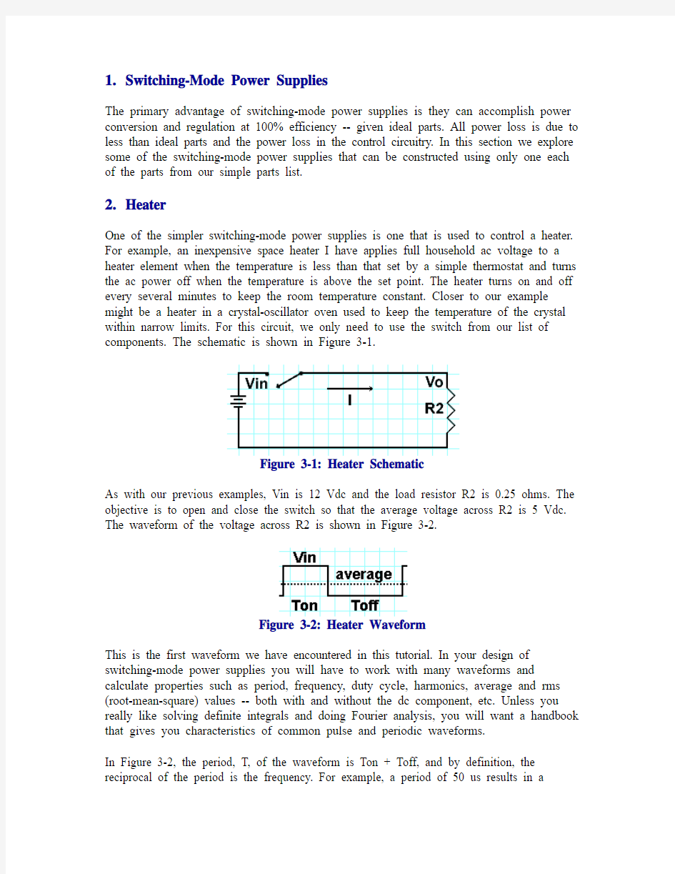
One of the simpler switching-mode power supplies is one that is used to control a heater. For example, an inexpensive space heater I have applies full household ac voltage to a heater element when the temperature is less than that set by a simple thermostat and turns the ac power off when the temperature is above the set point. The heater turns on and off every several minutes to keep the room temperature constant. Closer to our example might be a heater in a crystal-oscillator oven used to keep the temperature of the crystal within narrow limits. For this circuit, we only need to use the switch from our list of components. The schematic is shown in Figure 3-1.
Figure 3-1: Heater Schematic
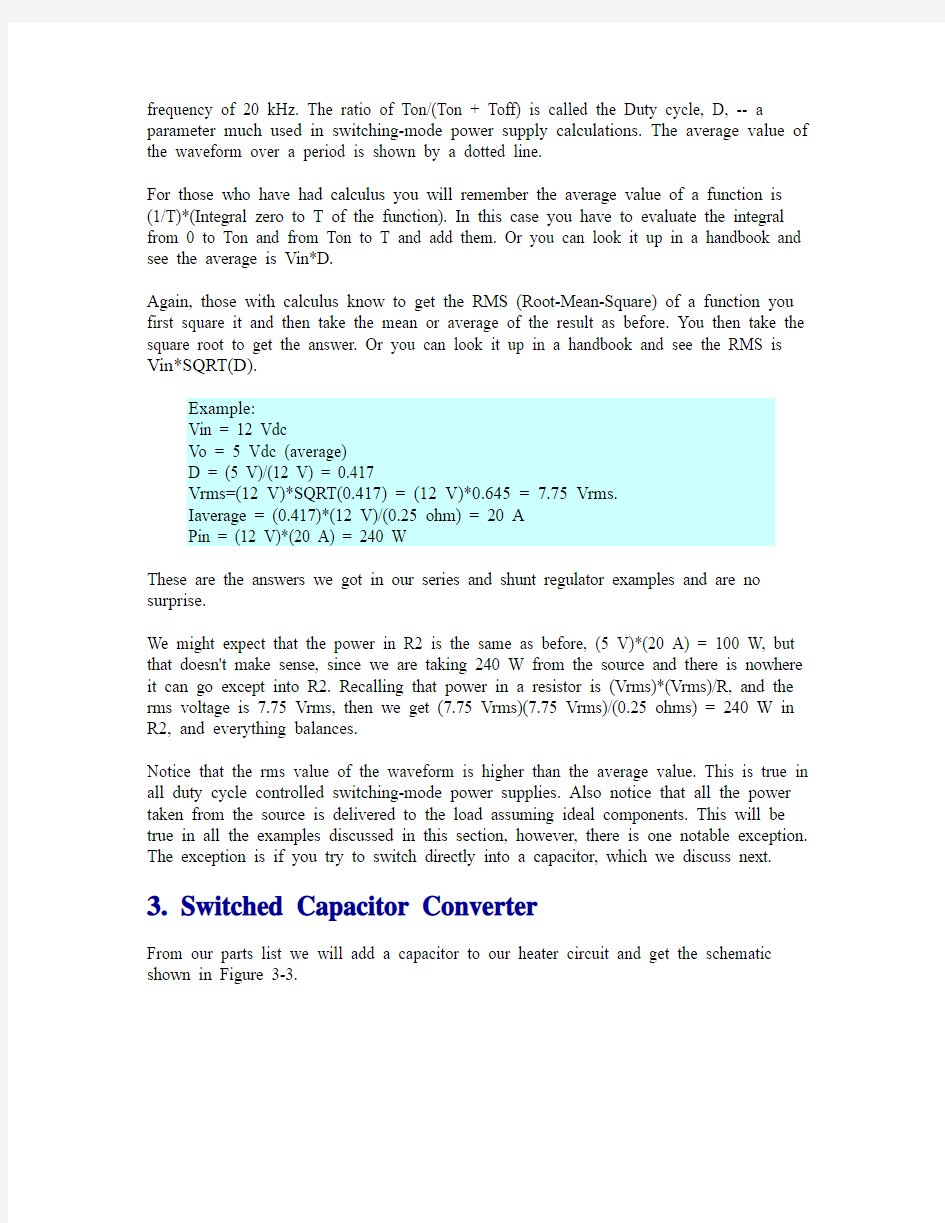
As with our previous examples, Vin is 12 Vdc and the load resistor R2 is 0.25 ohms. The objective is to open and close the switch so that the average voltage across R2 is 5 Vdc. The waveform of the voltage across R2 is shown in Figure 3-2.
Figure 3-2: Heater Waveform
This is the first waveform we have encountered in this tutorial. In your design of switching-mode power supplies you will have to work with many waveforms and calculate properties such as period, frequency, duty cycle, harmonics, average and rms (root-mean-square) values -- both with and without the dc component, etc. Unless you really like solving definite integrals and doing Fourier analysis, you will want a handbook that gives you characteristics of common pulse and periodic waveforms.
In Figure 3-2, the period, T, of the waveform is Ton + Toff, and by definition, the reciprocal of the period is the frequency. For example, a period of 50 us results in a
frequency of 20 kHz. The ratio of Ton/(Ton + Toff) is called the Duty cycle, D, -- a parameter much used in switching-mode power supply calculations. The average value of the waveform over a period is shown by a dotted line.
For those who have had calculus you will remember the average value of a function is (1/T)*(Integral zero to T of the function). In this case you have to evaluate the integral from 0 to Ton and from Ton to T and add them. Or you can look it up in a handbook and see the average is Vin*D.
Again, those with calculus know to get the RMS (Root-Mean-Square) of a function you first square it and then take the mean or average of the result as before. You then take the square root to get the answer. Or you can look it up in a handbook and see the RMS is Vin*SQRT(D).
Example:
Vin = 12 Vdc
Vo = 5 Vdc (average)
D = (5 V)/(12 V) = 0.417
Vrms=(12 V)*SQRT(0.417) = (12 V)*0.645 = 7.75 Vrms.
Iaverage = (0.417)*(12 V)/(0.25 ohm) = 20 A
Pin = (12 V)*(20 A) = 240 W
These are the answers we got in our series and shunt regulator examples and are no surprise.
We might expect that the power in R2 is the same as before, (5 V)*(20 A) = 100 W, but that doesn't make sense, since we are taking 240 W from the source and there is nowhere it can go except into R2. Recalling that power in a resistor is (Vrms)*(Vrms)/R, and the rms voltage is 7.75 Vrms, then we get (7.75 Vrms)(7.75 Vrms)/(0.25 ohms) = 240 W in R2, and everything balances.
Notice that the rms value of the waveform is higher than the average value. This is true in all duty cycle controlled switching-mode power supplies. Also notice that all the power taken from the source is delivered to the load assuming ideal components. This will be true in all the examples discussed in this section, however, there is one notable exception. The exception is if you try to switch directly into a capacitor, which we discuss next. 3.Switched Capacitor Converter
From our parts list we will add a capacitor to our heater circuit and get the schematic shown in Figure 3-3.
Figure 3-3: Switched Capacitor Converter
One might erroneously argue that the only dissipative element in this circuit is the load and all energy from the source goes to the load. Therefore if we control the switch to maintain 5 Vdc on the capacitor we have a 100% efficient converter. This is not the case since charging a capacitor directly from a voltage source or capacitor dissipates as much energy as is transferred to the capacitor. This problem, Energy Loss in Charging a Capacitor, is discussed in the problem section of the SMPS Technology Knowledge Base. Since you will see this circuit in many variations throughout your design career, it is well to recognize it and understand it. This circuit has it uses, but high efficiency power conversion from a source that is significantly different from the output is not one of them. In order to keep the voltages near each other and increase efficiency, many applications switch topologies during operation (e.g. from a voltage doubler to a tripler) to improve the efficiency of this circuit.
4.Switched Inductor Converter
From our parts list we will add an inductor and diode to our heater circuit and get the schematic shown Figure 3-4.
Figure 3-4: Switched Inductor Converter
Unlike our capacitor example, this circuit is 100% efficient with ideal components. It's major problem is terrible load transient response. If the load is removed, the current must continue to flow in the inductor and the output voltage tends to go to infinity. If the load is increased by two, the output voltage is halved, since the inductor current remains the same until adjusted by the L/R time constant. Because of the terrible load transient response this circuit is rarely used as a voltage regulator. But it is interesting to note that in the type of dc-dc converter we are discussing in this section, an inductor is always needed, but a capacitor is not. It is also interesting to note that this is the equivalent circuit of a switching-mode control of current in a motor field winding, which is represented as an inductor and series resistor.
Note that the diode is necessary to provide a current path for the inductor current when the switch opens. Otherwise the voltage across the inductor would build up to several hundred volts until the energy stored in the inductor would dissipate as an arc in the switch, charge the parasitic capacitance of the inductor windings, or result in some other undesired phenomenon.
A rule of thumb, which we will use later for selecting a value of inductance in an LC filter, is to start with an inductor value that results in a peak-to-peak inductor current that is 10% of the full load current. For our example of a 12 V input, 5 V output, 20 A load, and 20 kHz switching frequency, the inductor can be calculated from the formula V =
L*(di/dt). This is a formula you will constantly use in switching-mode power supply design, hence worth memorizing.
Example:
L = V*Ton/I
V = 12 V - 5 V = 7 V
Ton = D*T = 0.417*50E-6 = 20.85E-6
I = 20 A * 10% = 2 A
L = (7 V)*(20.85E-6 s)/(2 A) = 72.3 uH
=> 75 uH
The resulting two amps (1.94 A) peak-to-peak ripple current gives about a half volt peak-to-peak ripple current in the 5 V, 20 A load. Note that you can decrease the ripple current to as small as you want by increasing L, or make L smaller by allowing more ripple current.
5.Buck Converter
From our parts list we will add a capacitor to our switched inductor converter and get the buck converter as shown in Figure 3-5.
Figure 3-5: Buck Converter
The buck converter goes by many names, voltage step-down converter, current step-up converter, chopper, direct converter, et .al. No matter the name, converters derived from this topology account for a substantial percentage of all converters sold. Understanding its operation is basic to switching-mode power supply design.
Our first problem is to select initial values of L and C. Later the design can be optimized. In our switched inductor example we used the rule of thumb of designing L to get a peak-
to-peak ripple current of 10% of the full load output current and got a value of 75 uH. We will use overshoot to get a value for C and then check the output ripple.
The problem of overshoot, Output Filter Design - Overshoot, is discussed in the problem section of the SMPS Technology Knowledge Base and it is an important consideration in output filter design -- enough so that it is prudent to consider overshoot first, rather than output ripple as is normally done, so that overshoot is not forgotten. We will use a simple rule of thumb of making the characteristic impedance of the filter, Zo, equal the load resistor, which gives an overshoot of SQRT(2)= 1.41 and a slightly over-damped filter at full load. For our example, if our full load 20 A is removed, the 5 Vdc voltage goes to (5 V)*1.41 = 7.07 V.
Solving Zo=SQRT(L/C) for C = L/(Zo*Zo) = 75E-6/(0.25*0.25) = 1,200 uF
In checking for ripple we will use another formula that is used enough in switching-mode power supply design that it is worth memorizing, V = (1/C)*INTEGRAL( i(t)*dt), which combined with V=L*(di/dt) allows us to calculate output ripple due to the capacitor capacitive impedance (which is often less than the contribution of capacitor equivalent series resistance (ESR) to output ripple).
Example:
Solving for current as a function of time in the output capacitor
The current in the capacitor is the triangular current in the inductor which has
the slope K
K = di/dt = V/L, from V=L*(di/dt)
K = (12 V - 5 V)/(75 uH) = 0.093E+6 A/s
Solving for capacitor ripple voltage
V = (1/C)*INTEGRAL ((K*t)dt)
= (K/(2*C)*t^2
where t = Ton
Ton = D*T = 0.417*(50E-6 s) = 20.85E-6 s
V = ((0.093E+6 A/s)/(2*1200E-6 F))*(20.85E-6 s)*(20.85E-6 s)
= 0.0168 V
With less than 17 mV ripple due to the capacitance of C and assuming a 50 mV ripple specification, this would leave 33 mV for ripple due to the equivalent series resistance of C or for design margin. If we needed less overshoot or less ripple, we could experiment with other values of LC, however, this seems good enough for our tutorial purposes. Two useful properties for any filter are the characteristic impedance, Zo=SQRT(L/C), and the cutoff frequency, Fo = 1/(2*PI*SQRT(L*C). These can be calculated or read off of impedance graph paper. Impedance graph paper is so useful that it should always be handy. How to use it for many purposes will be discussed in this tutorial. Using impedance paper we look for the intersection of L and C and read Zo on the Ordinate and Fo on the Abscissa. Or we can calculate it.
Example:
Zo = SQRT(L/C) = SQRT(75E-6/1200E-6) = 0.25 ohms
Fo = 1/(2*PI*SQRT(LC)) = 1/(6.28*SQRT(75E-6*1200E-6) = 532 Hz
We will start our understanding of the buck converter by turning the switch on and off and examining what happens, first as a function of time and then in the state-plane.
6.Buck Converter Turn-On and Turn-Off Versus Time
First let's turn on the switch and watch what happens to the output voltage versus time. For illustrative purposes we want the filter under-damped so we will decrease the load by increasing the load resistor from 0.25 ohms to 1.0 ohms.
As shown in Figure 3-6, the SPICE simulation waveform overshoots 12 V to 16 V and then has a damped ringing related to the filter resonant frequency (532 Hz) and final settles at 11.5 V, the input voltage. If the filter were unloaded, it would overshoot to 24 V (twice the input voltage) and would oscillate between zero and 24 V at a frequency of 532 Hz.
Figure 3-6: Buck Converter Turn-On and Turn-Off Versus Time
The turn-off waveform starts at 12 V and exponentially decays to zero volts without ringing. The cycle then starts again.
It is instructive to look at both of these events in the state-plane.
7.Buck Converter Turn-On and Turn-Off in the State-Plane
The state-plane, sometimes called the phase-plane, is a plot with two state-variables as coordinates. State-variables are variables whose initial conditions are required to determine the future behavior of the system. Typically they are anything that stores energy, like inductors and capacitors, or anything with a memory, such as a flip-flop. Common state-planes in switching-mode power supply design are inductor current versus capacitor voltage in the output LC filter (approximates load current and load voltage), the
derivative of capacitor voltage (approximates the inductor current without the dc component) versus capacitor voltage, and the derivative of the output capacitor voltage versus the voltage (you do not have to be concerned with any currents and the derivative always crosses the voltage axis at right angles). Trajectories are unique for a set of initial conditions and never cross each other. Trajectories in the state-plane can easily be determined by most SPICE programs that are used to determine the time response of a circuit.
Figure 3-7 shows an approximate state-plane plot of the turn-on and turn-off events. The horizontal axis is the voltage across the output capacitor which approximates the output voltage. The vertical axis could one of several state-variables such as the inductor current, the derivative of the capacitor voltage, or the current through the capacitor. The inductor current, which approximates the load current is chosen. The steady-state turn-off conditions are 0 V and 0 A. The steady-state turn-on conditions are 12 V and 12 A (point one in the plot). The trajectories to reach these steady state conditions are shown in state-plane, Figure 3-7.
Figure 3-7: Buck Converter Turn-On and Turn-Off State-Plane
Turn-on
If there were no load, then the normalized turn-on trajectory would trace a clockwise circle reaching a positive peak current of Vin/Zo = (12 V)/(0.25 ohm) = 48 A, a peak voltage of twice the input voltage, 2*(12 V) = 24 V, and negative current equal to the positive current, return to zero volts, and then repeat itself until the circuit is disturbed, since there is nothing in the circuit that dissipates energy.
Since there is a load to dissipate energy, the circle spirals in to the steady state value of
12 V and 12 A (point 1) as energy is lost to the load or other dissipative elements as shown in Figure 3-7.
The state-plane turn-on trajectory tells us some things about this circuit that are worth remembering. On turn-on, buck-derived converters (and LC filters in general) tend to overshoot the final voltage, and can have an in-rush current much greater than the load current. Later in the design cycle it may be necessary to compensate for these inherent turn-on characteristics by adding soft-start circuits and in-rush current-limiting circuits to the design.
Also, the turn-on characteristics are dependent on the type of switch. In our ideal example, the switch can pass the inductor current in either direction, which is true of a relay contact or a power MOSFET, where the body parasitic diode will conduct current in the reverse direction. Other switches may not behave this way. For example, the reverse current behavior of a bipolar transistor depends on the reverse beta of the transistor and the base drive current. For old alloy junction transistors, the reverse and forward beta can be the same. For modern planar bipolar transistors, the reverse beta may be less than one and the transistor can carry only a small fraction of the forward current in the reverse direction. If the switch can not carry current in the reverse direction, the voltage rings up to the first peak and stays there until the load discharges it.
The bottom line is that you have to thoroughly know the behavior of the power switch to design reliable circuits. Later we will discuss switch topics such as secondary break-down, Safe Operating Areas (SOA), and parasitic elements that are important things to know about a switch. Here we see that it can be important to know how a switch behaves in quadrants other than its normal forward conduction quadrant.
Turn-off
The turn-of trajectory starts at 12 V and 12 A. The inductor keeps supplying 12 V to the load until it reaches zero amperes. Since the diode does not allow current to go below zero amperes, the voltage then drops along the zero ampere axis until it reaches its turn-off steady-state value of zero volts at zero amperes. There is no ringing in the waveform since the non-linear diode does not allow either voltage or current to go negative.
8.Bang-Bang, Ripple, or Hysteresis Control
One easy way to turn our prototype buck converter into a 5 V regulator is to sense the output and turn the switch on when the voltage is less than 5 V and turn the switch off when the voltage is greater than 5 V. This form of control is called by various names including bang-bang control, ripple regulators, and hysteretic control. It is instructive to exam this operation in the state-plane. For the following plots the values of L and C are the same (75 uH and 1200 uF) but load is one ohm instead of 0.25 ohm (less damping shows the effects better).
Figure 3-8 shows bang-bang or hysteretic control with no hysteresis. The black line (1) is output voltage (voltage across the output capacitor) versus time, the blue line is inductor current (2) versus time, and the green line (3) is inductor current plotted versus capacitor voltage - the state plane for the two energy storage devices, L and C.
Figure 3-8: Bang-Bang Control - No Hysteresis
At time zero the switch representing the transistor is turned on and the voltage and current increase until the voltage reaches 5.0V. At this point the switch is turned off and the current starts to decrease. However, the voltage across the output capacitor continues to increase as long as current in the inductor is greater than the load current. The current drops to zero but does not reverse since the switch and diode will not allow this. When the voltage decays to 5.0V, the switch is turned again and voltage and current start to increase. This action is repeated with the amplitude of the voltage ripple and current ripple decreasing each cycle and the frequency increasing each cycle. In the limit the frequency becomes infinite and the ripple becomes zero and all that is left is a series dissipative regulator with an LC output filter. In this example, the initial cycle frequency is about 4.76 kHz, the voltage ripple is 30 mVp-p and the current ripple is 10Ap-p. This
is seen on the state-plane in the outer limit of the green ellipse at (3). The ellipse is filled in as the ripple goes to zero and the frequency goes to infinity and we get a series dissipative regulator.
This we do not want. How do we keep things switching? By adding either a time delay in the control loop (time hysteresis) or voltage hysteresis in the comparator that senses the output voltage. In practice there is always some time delay in real components and the regulator may settle into some stable switching frequency. However, this is not dependable and a controlled delay or voltage hysteresis must be added.
Figure 3-9 shows the same circuit with a 1.2 microsecond delay added to the control loop.
Figure 3-9: Bang-Bang Control - Delay Hysteresis
The 1.2 microsecond delay in the feedback loop has stabilized the frequency at about 12.5 kHz with 25 mVp-p voltage ripple and 3 Ap-p current ripple. However, the overshoot is just as bad as the circuit without hysteresis. (This is shown in the state plane but not the voltage and current time plots which show the steady state, not the start-up transient.) How do we cure this? With a soft-start circuit.
Figure 3-10 shows the startup with a soft-start circuit. The soft start is implemented in this case by slowly bringing up the reference voltage.
Figure 3-10: Bang-Bang Control with Soft Start Circuit
The red line (2) is the 5V reference voltage and ramps up from zero to 5V in 2 milliseconds. The black line (hidden 1) is the output voltage which follows the reference ramp except every time it makes a comparison to the reference and finds it is low, it turns on and overshoots the reference. At 2 ms it overshoots the desired 5V slightly and then after several oscillations settles into the steady state ripple. The green line (4) shows this action in the inductor-current versus output-voltage state plane.
Figure 3-11 shows the switching details during steady state conditions. The black line (1) is the output voltage ripple, the blue line (2) is the ripple current in the inductor, and the green line (3) is the ripple current versus the ripple voltage in the state-plane. To this has been a vertical red line added at the 5V switching line.
Figure 3-11: Switching Line Detail
When the upper green trace intercepts the red switching line, the comparator commands the switch to open. But due to the 1.2 microsecond delay added, the switching occurs some what later. The same with the lower green trace. This shows how the time hysteresis controls the output ripple and switching frequency (which is related in a somewhat complex way to the area traced by the trajectory). Note that although a time delay is used here, by putting two switching lines at the switch points (a comparator with voltage hysteresis) the ripple and frequency can be controlled by voltage hysteresis. Current hysteresis switching lines could also be used. Since all circuits have delays, the ripple and frequency are usually controlled by time delay and comparator hysteresis in real circuits. The switching line does not have to be fixed. For example, one converter uses as reference a fixed frequency triangle derived by chopping a dc reference and integrating the result into a triangle used as a reference for the comparator. This gives a fixed frequency of operation combined with the advantages of fast transient response and 90 degrees phase shift.
The state-plane is a very powerful way to look at switching-mode power supplies. For example, here we see a steady state response for one set of line and load conditions. Other sets of line and load conditions have their steady states. The state-plane can be used to find the optimum switching strategy between the two steady state conditions, optimum in that there is only one switching point that will allow a transition from one steady-state to the other steady state with a single off-on switching set. The state-plane has been used in this manner to determine optimum controllers for switching-mode power supplies. All modern Spice programs, including the free demonstration programs, allow plotting the state-plane and provide a powerful tool for examining switching-mode power supplies. I highly recommend looking at them as part of your simulation and using them to learn more about switching-mode power supplies. Ask yourself how does the state-plane change if I change the input voltage? How does it change if I change the load? What does
the transition look like in the state plane for these changes. One caution is that you usually have to control the maximum step size to get smooth plots. Using the usual defaults for Spice time plots usually produces jagged state-plane plots. For the plots in this tutorial, I usually set the maximum step size to the data step time. This increases the time somewhat needed to complete a simulation but makes much cleaner state-plane plots. Bang-bang control is very easy to implement. All circuits have a time delay, so a simple comparator comparing a reference to the output usually works -- and can always be made to work by adding an extra time delay. However, control is usually implemented using a comparator with hysteresis, hence the term hysteretic control. Whence the name bang-bang? This type of control is often used to control rocket and satellite control thrusters where a valve is either fully on or fully off. When tested in the atmosphere, these thrusters make a bang each time the are operated. When a control system is trying to lock on to a target, these thrusters can sound like the loudest machine-gun you have every heard. Definitely bang-bang!
Besides simplicity, bang-bang or hysteretic controllers only have 90 degrees phase shift which makes them easy to stabilize, and a rapid transient response. With these advantages, why do most power supplies use pulse-width-modulation (PWM) control instead? A minor reason is that hysteretic converters are more prone to chaos than other converters. But the major reason is their tendency to synchronize or entrain with a switching load, a periodic input voltage, or random noise -- often with unwanted or disastrous results, such as ripple on a five volt logic converter increasing from a tens of millivolts to several volts. All converters can do this, but bang-bang controllers are far more susceptible to this problem than PWM controllers. Entrainment will be discussed in detail in an upcoming problem/solution discussion.
功率因数校正之基本原理
功率因数校正之基本原理 何谓工率因数? 功率因数(power factor;pf)定义为实功(real power;P)对视在功率(apparent power;S)之比,或代表电压与电流波形所形成之相角之余弦,如图1。功率因数值可由0至1之间变化,可为电感性(延迟的、指标向上)或电容性(领先的、指标向下)。为了降低电感性之延迟,可增加电容,直到pf为1。当电压与电流波形为同相时,工率因数等于1(cos(0o)=1)。所有努力使工率因数等于1是为了使电路为纯电阻化(实功等于视在功率)。 ▲图1: 功率因数之三角关系。 实功(瓦特)可提供实际工作,此为能量转换元素(例如电能到马达转动rpm)。虚功(reactive power)乃为使实功完成实际工作所产生之磁场(损耗)。而视在功率可想成电力公司提供之总功率,如图1所示。此总功率经由电力线提供产生所需之实功。 当电压与电流皆为正弦波时,如前述定义之功率因数(简称为功因)为电压与电流波形之对应相角,但大部份之电源供应器之输入电流乃非正弦波。当电压为正弦波而电流为非正弦波时,则功因包括两个因素:1)相角位移因素,2)波形失真因素。等式1表示相角位移与波形失真因素之于功因的关系。 ----------------------------------------------------(1)
Irms(1)为电流之主成份,Irms电流之均方根值。因此功率因数校正线路是为了使电流失真最小,且使电流与电压同相。 当功因不等于1时,电流波形没有跟随电压波形,不但有功率损耗,且其产生之谐波透过电力线干扰到连接同一电力线之其它装置。功因越接近1,几乎所有功率皆包含于主频率,其谐波越接近零。 ■了解规范 EN61000-3-2对交流输入电流至第40次谐波规范。而其class D对适用设备之发射有严格之限制(图2)。其class A要求则较宽松(图3)。 ▲图2:电压与电流波形同相且PF=1(Class D)。
钢结构设计原理(答案)
一、 填空题(每空1分,共10分) 1、钢材的两种破坏形式分别为脆性破坏和 。 2、焊接的连接形式按构件的相对位置分为 、搭接、角接和T 形连 接。 3、钢结构中轴心受力构件的应用十分广泛,其中轴心受拉构件需进行钢结构强度和 的验算。 4、轴心受压构件整体屈曲失稳的形式有 、和 。 5、梁整体稳定判别式11l b 中,1l 是 1b 。 6、静力荷载作用下,若内力沿侧面角焊缝没有均匀分布,那么侧面角焊缝的计算长度不宜大于 。 7、当组合梁腹板高厚比0w h t ≤ 时,对一般梁可不配置加劲肋。 二、 单项选择题(每题2分,共40分) 1、有两个材料分别为Q235和Q345钢的构件需焊接,采用手工电弧焊, 采用E43焊条。 (A)不得 (B)可以 (C)不宜 (D)必须 2、工字形轴心受压构件,翼缘的局部稳定条件为y f t b 235) 1.010(1λ+≤,其中λ的含义为 。 (A)构件最大长细比,且不小于30、不大于100 (B)构件最小长细比 (C)最大长细比与最小长细比的平均值 (D)30或100 3、偏心压杆在弯矩作用平面内的整体稳定计算公式
x 1(10.8') mx x x x Ex M f A W N N βN ?γ+≤-中,其中,1x W 代表 。 (A)受压较大纤维的净截面抵抗矩 (B)受压较小纤维的净截面抵抗矩 (C)受压较大纤维的毛截面抵抗矩 (D)受压较小纤维的毛截面抵抗矩 4、承重结构用钢材应保证的基本力学性能内容应是 。 (A)抗拉强度、伸长率 (B)抗拉强度、屈服强度、冷弯性能 (C)抗拉强度、屈服强度、伸长率 (D)屈服强度、伸长率、冷弯性能 5、随着钢材厚度的增加,下列说法正确的是 。 (A)钢材的抗拉、抗压、抗弯、抗剪强度均下降 (B)钢材的抗拉、抗压、抗弯、抗剪强度均有所提高 (C)钢材的抗拉、抗压、抗弯强度提高,而抗剪强度下降 (D)视钢号而定 6、在低温工作(-20oC)的钢结构选择钢材除强度、塑性、冷弯性能指标外,还需要 的指标是 。 (A)低温屈服强度 (B)低温抗拉强度 (C)低温冲击韧性 (D)疲劳强度 7、直角角焊缝的有效厚度e h 的取值为 。 (A)0.7f h (B)4mm (C)1.2f h (D) 1.5f h 8、对于直接承受动力荷载的结构,计算正面直角焊缝时 。 (A)要考虑正面角焊缝强度的提高 (B)要考虑焊缝刚度影响 (C)与侧面角焊缝的计算式相同 (D)取f β=1.22 9、单个螺栓的承压承载力中,[b b c c N d t f =?∑],其中∑t 为 。 (A)a+c+e (B)b+d (C)max{a+c+e ,b+d} (D)min{ a+c+e , b+d} 10、承压型高强度螺栓可用于 。
混凝土结构设计原理复习重点(非常好)
混凝土结构设计基本原理复习重点(总结很好) 第 1 章绪论 1.钢筋与混凝土为什么能共同工作: (1)钢筋与混凝土间有着良好的粘结力,使两者能可靠地结合成一个整体,在荷载作用下能够很好地共同变形,完成其结构功能。 (2)钢筋与混凝土的温度线膨胀系数也较为接近,因此,当温度变化时,不致产生较大的温度应力而破坏两者之间的粘结。 (3)包围在钢筋外面的混凝土,起着保护钢筋免遭锈蚀的作用,保证了钢筋与混凝土的共同作用。 1、混凝土的主要优点:1)材料利用合理2 )可模性好3)耐久性和耐火性较好4)现浇混凝土结构的整体性好5)刚度大、阻尼大6)易于就地取材 2、混凝土的主要缺点:1)自重大2)抗裂性差3 )承载力有限4)施工复杂、施工周期较长5 )修复、加固、补强较困难 建筑结构的功能包括安全性、适用性和耐久性三个方面 作用的分类:按时间的变异,分为永久作用、可变作用、偶然作用 结构的极限状态:承载力极限状态和正常使用极限状态 结构的目标可靠度指标与结构的安全等级和破坏形式有关。 荷载的标准值小于荷载设计值;材料强度的标准值大于材料强度的设计值 第2章钢筋与混凝土材料物理力学性能 一、混凝土 立方体抗压强度(f cu,k):用150mm×150mm×150mm的立方体试件作为标准试件,在温度为(20±3)℃,相对湿度在90%以上的潮湿空气中养护28d,按照标准试验方法加压到破坏,所测得的具有95%保证率的抗压强度。(f cu,k为确定混凝土强度等级的依据) 1.强度轴心抗压强度(f c):由150mm×150mm×300mm的棱柱体标准试件经标准养护后用标准试验方法测得的。(f ck=0.67 f cu,k) 轴心抗拉强度(f t):相当于f cu,k的1/8~1/17, f cu,k越大,这个比值越低。 复合应力下的强度:三向受压时,可以使轴心抗压强度与轴心受压变形能力都得到提高。 双向受力时,(双向受压:一向抗压强度随另一向压应力的增加而增加;双向受拉:混凝土的抗拉强度与单向受拉的基本一样; 一向受拉一向受压:混凝土的抗拉强度随另一向压应力的增加而降低,混凝土的抗压强度随另一向拉应力的增加而降低) 受力变形:(弹性模量:通过曲线上的原点O引切线,此切线的斜率即为弹性模量。反映材料抵2.变形抗弹性变形的能力) 体积变形(温度和干湿变化引起的):收缩和徐变等。 混凝土单轴向受压应力-应变曲线数学模型 1、美国E.Hognestad建议的模型 2、德国Rusch建议的模型 混凝土的弹性模量、变形模量和剪变模量 弹性模量 变形模量 切线模量 3、(1)徐变:混凝土的应力不变,应变随时间而增长的现象。 混凝土产生徐变的原因: 1、填充在结晶体间尚未水化的凝胶体具有粘性流动性质 2、混凝土内部的微裂缝在载荷长期作用下不断发展和增加的结果 线性徐变:当应力较小时,徐变变形与应力成正比;非线性徐变:当混凝土应力较大时,徐变变形与应力不成正比,徐变比应力增长更快。影响因素:应力越大,徐变越大;初始加载时混凝土的龄期愈小,徐变愈大;混凝土组成成分水灰比大、水泥用量大,徐变大;骨料愈坚硬、弹性模量高,徐变小;温度愈高、湿度愈低,徐变愈大;尺寸大小,尺寸大的构件,徐变减小。养护和使用条件 对结构的影响:受弯构件的长期挠度为短期挠度的两倍或更多;长细比较大的偏心受压构件,侧向挠度增大,承载力下降;由于徐变产生预应力损失。(不利)截面应力重分布或结构内力重分布,使构件截面应力分布或结构内力分布趋于均匀。(有利) (2)收缩:混凝土在空气中结硬时体积减小的现象,在水中体积膨胀。 影响因素:1、水泥的品种:水泥强度等级越高,则混凝土的收缩量越大; 2、水泥的用量:水泥越多,收缩越大;水灰比越大,收缩也越大; 3、骨料的性质:骨料的弹性模量大,则收缩小; 4、养护条件:在结硬过程中,周围的温、湿度越大,收缩越小; 5、混凝土制作方法:混凝土越密实,收缩越小; 6、使用环境:使用环境的温度、湿度大时,收缩小; 7、构件的体积与表面积比值:比值大时,收缩小。 对结构的影响:会使构件产生表面的或内部的收缩裂缝,会导致预应力混凝土的预应力损失等。 措施:加强养护,减少水灰比,减少水泥用量,采用弹性模量大的骨料,加强振捣等。 混凝土的疲劳是荷载重复作用下产生的。(200万次及其以上) 二、钢筋 光圆钢筋:HPB235 表面形状 带肋钢筋:HRB335、HRB400、RRB400 有明显屈服点的钢筋:四个阶段(弹性阶段、屈服阶段、强化阶段、破坏阶段),屈服强度力学性能是主要的强度指标。 (软钢)
英语常考标志词
标志词巧解语法和改错 标志词 1. 逗号 在语法填空中,逗号隔开一个词;如果有提示词 , 提示词是 adj ,则填这个词的副词形式,大多加 ly ;如果提示词是 v, 则填写它的非谓语形式。 如果无提示词,则优先考虑 however ,therefore, 其次考虑 moreover ,otherwise 。 例: Luckily (luck), he escaped from the fire. Unfortunately (unfortunate) , he fell off the bike. He earned a lot of money , however, he was addicted in the drug. 标志词 2. one of one of 之后若有形容词,一定要用最高级形式;若之后出现名词,则用复数形式;若既有名词又有形容词,则先填最高级,再填复数名词,最高级之前要加 the 例: The house is one of the cheapest (cheap) houses in the area. 标志词 3. when 与 while( 时间状语从句) when 之后一般要用过去式, while 之后一般要用过去进行时。 例: When I got home, my mother was cooking dinner. While my mother was cooking dinner, I entered the kitchen. 标志词 4. by 语法填空里,空格之后有“by” ” ,则空格里考虑填“be + 动词的过去分词”, 但是如果前面已经有了谓语动词,则空格里直接用“ 过去
钢结构设计基本原理课后答案 肖亚明
合肥工业大学出版社出版 (肖亚明主编) 第三章 1. 解:Q235钢、2/160mm N f w f =、kN N 600= (1)采用侧面角焊缝 最小焊脚尺寸:mm t h f 6.5145.15.1max =?=≥ 角钢肢背处最大焊脚尺寸:mm t h f 12102.12.1min =?=≤ 角钢肢尖处最大焊脚尺寸:mm t h f 8~9)2~1(10)2~1(=-=-≤ 角钢肢尖和肢背都取 mm h f 8= 查表3-2得:65.01=K 、35.02=K kN N K N 39060065.011=?==,kN N K N 21060035.022=?== 所需焊缝计算长度: mm f h N l w f f w 63.217160 87.02103907.023 11 =????=?= mm f h N l w f f w 19.11716087.02102107.023 22 =????=?= 焊缝的实际长度为: mm h l l f w 63.2338263.217211=?+=+=,取240mm 。 mm h l l f w 19.1338219.117222=?+=+=,取140mm 。 (2)采用三面围焊缝,取mm h f 6= 正面角焊缝承担的内力为: kN f l h N w f f w f 97.16316022.1100267.07.033=?????==∑β 侧面角焊缝承担的内力为: kN N N K N 01.3082/97.16360065.02/311=-?=-= kN N N K N 02.1282/97.16360035.02/322=-?=-= 所需焊缝计算长度:
《混凝土结构基本原理》练习题
《混凝土结构基本原理》练习题 一、单选题 1.与素混凝土梁相比,钢筋混凝土梁承载能力(C )。 A.相同B、有所降低 C.提高很多 D.提高很少 2.与素混凝土梁相比,钢筋混凝土梁抵抗开裂的能力(C)。 A.相同 B.有所降低 C.提高不多 D.提高很多 3.就混凝土的徐变而言,下列几种叙述中( D )不正确。 A.徐变是在荷载长期作用下,混凝土的变形随时间的延长而增长的现象。 B.持续应力的大小对徐变有重要影响。 C.徐变对结构的影响,多数情况下是不利的。 D.水灰比和水泥用量越大,徐变越小。 4.线性徐变是指(C )。 A.徐变与荷载持续时间为线性关系 B.徐变系数与初应力为线性关系 C.徐变与初应力为线性关系 D.瞬时变形与初应力为线性关系 5.对于无明显屈服点的钢筋,其强度取值的依据是( D )。 A.最大应变对应的应力 B.极限抗拉强度 C.0.9极限强度 D.条件屈服强度 6.钢筋的混凝土保护层厚度是指:(A) A.纵向受力钢筋外表面到构件外表面的最小距离 B.纵向受力钢筋形心到构件外表面的距离 C.箍筋外表面到构件外表面的最小距离 D.纵向受力钢筋的合力点到构件外表面的最小距离 7.超筋梁正截面受弯承载力与(A)。 A.混凝土强度有关 B.配筋强度f y A s有关 C.混凝土强度和配筋强度都有关 D.混凝土强度和配筋强度都无关 8.受弯构件正截面弯曲破坏形态的决定性因素是(C)。 A.荷载大小 B.混凝土强度等级 C.计算受压区高度 D.箍筋用量 9.钢筋混凝土单筋矩形截面适筋梁,若截面尺寸给定,混凝土及钢筋强度给定,则配筋率ρ越大(A )。 A.破坏时受压区高度越大 B.破坏时的变形越大 C.破坏时受压区边缘的压应变越大 D.破坏时受拉钢筋的应变越大 10.提高梁的配箍率可以(D )。 A.显著提高斜裂缝开裂荷载 B.防止斜压破坏的出现 C.使斜压破坏转化为剪压破坏 D.在一定范围内可以提高抗剪承载力 11.双筋矩形截面受弯构件设计时,当受压区x<2a s’时,表明(B )。 A.受拉钢筋不屈服 B.受压钢筋不屈服 C.受拉、受压钢筋均不屈服 D.应加大截面尺寸 12.钢筋与混凝土之间的粘结强度(D)。 A.随外荷载增大而增大 B.随钢筋强度增加而增大 C.随钢筋埋入混凝土中的长度增加而增大 D.随混凝土强度等级提高而增大 13.限制箍筋最大间距的目的主要是(B )。 A.控制箍筋的配筋率 B.保证箍筋和斜裂缝相交 C.防止出现斜压破坏 D.保证箍筋的直径不致太大 14.提高受弯构件抗弯刚度最有效的措施是( C )。 A.增加受拉钢筋截面面积 B.采用高强钢筋 C.增大构件截面有效高度 D.采用高强度等级混凝土
LLC 电路基本原理分析及公式推导
Simplified Analysis and Design of Series-resonant LLC Half-bridge Converters MLD GROUP INDUSTRIAL & POWER CONVERSION DIVISION Off-line SMPS BU Application Lab I&PC Div. - Off-line SMPS Appl. Lab
Presentation Outline ?LLC series-resonant Half-bridge: operation and significant waveforms ?Simplified model (FHA approach) ?300W design example I&PC Div. - Off-line SMPS Appl. Lab
Series-resonant LLC Half-Bridge Topology and features Q1 Cr Ls Vin Q2 Lp LLC tank circuit Preferably integrated into a single magnetic structure 3 reactive elements, 2 resonant frequencies 1 f r1 2?π?Ls?Cr f>f r1r2Center-tapped output with full- wave rectification (low voltage and high current) Vout Vout Single-ended output with bridge rectifiication (high voltage and low current) Multiresonant LLCtank circuit Variable frequency control Fixed50%duty cycle for Q1&Q2 Deadtime between LGandHGto allow MOSFET’s ZVS@turnon fsw≈fr,sinusoidal waveforms:low turnofflosses,low EMI Equal voltage¤t stressfor secondary rectifiers;ZCS,then no recovery losses Nooutputchoke;cost saving Integrated magnetics:both L’scan be realized with thetransformer. Highefficiency:>96%achievable
钢结构基本原理课程设计
2013级土木工程专业 《钢结构》课程设计任务书 钢结构课程是土木工程专业重要的实践性教学环节,是对学生知识和能力的总结。通过钢结构课程设计,使学生进一步了解钢结构的结构型式、结构布置和受力特点,掌握钢结构的计算简图、荷载组合和内力分析,掌握钢结构的构造要求等。要求在老师的指导下,参考已学过的课本及有关资料,综合应用钢结构的材料、连接和基本构件的基本理论、基本知识,进行基本的钢结构设计计算,并绘制钢结构施工图。 设计题目: 钢结构平台梁板柱的设计 设计资料: (a) (b) (a) 梁格布置(b) 次梁布置简图 钢结构平台的梁格布置如如上图所示。铺板为预制钢筋混凝土板。平台永久荷载(包括铺板重力)为5kN/m2,荷载分项系数为,可变荷载分项系数为m2,荷载分项系数为;活荷载F=,钢材采用Q235,E43型焊条,焊条电弧焊。试对此钢结构平台的次梁、主梁和柱子(包括柱脚)进行设计。 要求: 1.每位同学自己独立完成,不能有任何雷同的课程设计计算书,否则都记为不及格; 2.课程设计计算书可以手写也可以打印,打印使用A4纸张; 3.完成并提交期限时间为第15周周五(12月9日)。 提示:可以参考教材P131例题4-2,P135例题4-4,P149习题4-10,P186习题5-2。
《课程设计说明书》格式规范 一、封面要求 学生提交的正稿封面样式附后。评定成绩必须有教师签名并写出评语。 二、正文规范 1、字体字号要求 ①设计标题用小三号黑体、居中,英文标题对应用小三号Times New Roman、居中,“摘要”用5号黑体,中文摘要内容用5号宋体,“Abstract”用5号黑体,英文摘要内容用5号Times New Roman。 ②课程设计正文内容 第一级标题用四号黑体、靠左;第二级标题用小四号黑体、靠左;正文全文用小四号宋体、英文用Times New Roman 12。 ③页码用小五号居中,页码两边不加修饰符,页码编号从正文开始。 ④图表标题用小五号黑体,居图表幅宽中间位置。 2、内容要求 ①正文必须按照《湖南农业大学学报(自然科学版)》要求,即包括完整的标题、作者、指导教师、中英文摘要、前言、方案比较分析、设计计算、讨论、小结、参考文献、致谢、附录含计算数据、参考手册相关计算表格等。 ②文理通顺、说理有据。 ③图表中文标题下必须有英文对照。
第四版混凝土结构设计原理试题库及其参考答案
第四版混凝土结构设计原理试题库及其参考答案 一、判断题(请在你认为正确陈述的各题干后的括号内打“√”,否则打“×”。每小题1分。) 第1章 钢筋和混凝土的力学性能 1.混凝土立方体试块的尺寸越大,强度越高。( ) 2.混凝土在三向压力作用下的强度可以提高。( ) 3.普通热轧钢筋受压时的屈服强度与受拉时基本相同。( ) 4.钢筋经冷拉后,强度和塑性均可提高。( ) 5.冷拉钢筋不宜用作受压钢筋。( ) 6.C20表示f cu =20N/mm 。( ) 7.混凝土受压破坏是由于内部微裂缝扩展的结果。( ) 8.混凝土抗拉强度随着混凝土强度等级提高而增大。( ) 9.混凝土在剪应力和法向应力双向作用下,抗剪强度随拉应力的增大而增大。( ) 10.混凝土受拉时的弹性模量与受压时相同。( ) 11.线性徐变是指压应力较小时,徐变与应力成正比,而非线性徐变是指混凝土应力较大时,徐变增长与应力不成正比。( ) 12.混凝土强度等级愈高,胶结力也愈大( ) 13.混凝土收缩、徐变与时间有关,且互相影响。( ) 第1章 钢筋和混凝土的力学性能判断题答案 1. 错;对;对;错;对; 2. 错;对;对;错;对;对;对;对; 第3章 轴心受力构件承载力 1.轴心受压构件纵向受压钢筋配置越多越好。( ) 2.轴心受压构件中的箍筋应作成封闭式的。( ) 3.实际工程中没有真正的轴心受压构件。( ) 4.轴心受压构件的长细比越大,稳定系数值越高。( ) 5.轴心受压构件计算中,考虑受压时纵筋容易压曲,所以钢筋的抗压强度设计值最大取为2/400mm N 。( ) 6.螺旋箍筋柱既能提高轴心受压构件的承载力,又能提高柱的稳定性。( ) 第3章 轴心受力构件承载力判断题答案 1. 错;对;对;错;错;错; 第4章 受弯构件正截面承载力 1.混凝土保护层厚度越大越好。( ) 2.对于' f h x 的T 形截面梁,因为其正截面受弯承载力相当于宽度为' f b 的
最新物质结构与性质知识点总结(1)
物质结构与性质知识点总结 专题一了解测定物质组成和结构的常用仪器(常识性了解)。 专题二第一单元 1.认识卢瑟福和玻尔的原子结构模型。 2.了解原子核外电子的运动状态,了解电子云的概念。 3.了解电子层、原子轨道的概念。 4.知道原子核外电子排布的轨道能级顺序。知道原子核外电子在一定条件下会发生跃迁。 5.了解能量最低原理、泡利不相容原理、洪特规则,能用电子排布式、轨道表示式表示1-36号元素原子的核外电子排布。 第二单元 1.理解元素周期律,了解元素周期律的应用。 2.知道根据原子外围电子排布特征,可把元素周期表分为不同的区。 3.了解元素第一电离能、电负性的概念及其周期性变化规律。(不要求用电负性差值判断共价键还是离子键) 4.了解第一电离能和电负性的简单应用。 专题三第一单元 1.了解金属晶体模型和金属键的本质。 2.能用金属键理论解释金属的有关物理性质。了解金属原子化热的概念。 3.知道影响金属键强弱的主要因素。认识金属物理性质的共性。 4.认识合金的性质及应用。 注:金属晶体晶胞及三种堆积方式不作要求。 第二单元 1.认识氯化钠、氯化铯晶体。 2.知道晶格能的概念,知道离子晶体的熔沸点高低、硬度大小与晶格能大小的关系。 3.知道影响晶格能大小的主要因素。 4.离子晶体中离子的配位数不作要求。 第三单元 1.认识共价键的本质,了解共价键的方向性和饱和性。 2.能用电子式表示共价分子及其形成过程。认识共价键形成时,原子轨道重叠程度与共价键键能的关系。 3.知道σ键和π键的形成条件,了解极性键、非极性键、配位键的概念,能对一些常见简单分子中键的类型作出判断。注:大π键不作要求 4.了解键能的概念,认识影响键能的主要因素,理解键能与化学反应热之间的关系。 5.了解原子晶体的特征,知道金刚石、二氧化硅等常见原子晶体的结构与性质的关系。 第四单元 1.知道范德华力和氢键是两种最常见的分子间作用力。 2.了解影响范德华力的主要因素,知道范德华力对物质性质的影响。 3.了解氢键的概念和成因,了解氢键对物质性质的影响。能分析氢键的强弱。
英语听力的十大类标志词
英语听力的十大类标志词 1.级标志词 形容词、副词级、most / chief / primary / main / leading / …… 2.级标志词 only / unique / prefer / every / one / of all / perfect / …… 3.因果项标志词 cause / lead to / contribute to / thanks to / owing to / question / answer / why / reason / 其他形式的问句/ …… 4.转则项关键词 despite / in spite of / instead / while / from ~ to ~ / although ~ (yet)~ / not only ~ but also ~ / …… 5.序数项标志词 所有的序数词(first , second)/ another / the other / next / last / in addition / on the other hand / …… 6.时间项标志词 when / how / today / as / before / after / since / then / until / …… 7.解释项标志词 or / namely / in other words / that is / that is to say / …… 8.目的项标志词
to / for / …… 9.总结项标志词 all in all / in brief / to conclude / at last / in summary / in short / …… 10.强调项标志词 副词:especially / particularly / almost / always / usually / …… 动词:show / remember / note / notice / say / pronounce / ……
混凝土结构基本原理模拟题
《混凝土结构基本原理》模拟题(补) 一、单项选择题 1.当某剪力墙连梁刚度较小,墙肢刚度较大时(相当于α<10 的情况),说明该剪力墙为(C ) A.整体墙 B. 小开口剪力墙 C. 联肢墙 D. 壁式框架 2.在确定高层建筑防震缝最小宽度时,下列说法不正确的是(D ) A.设防烈度越高,最小缝宽取值越大 B. 结构抗侧移刚度越小,最小缝宽取值越大 C. 相邻结构单元中较低单元屋面高度越高,最小缝宽取值越大 D. 相邻结构单元中较高单元屋面高度越高,最小缝宽取值越大 3.有4 个单质点弹性体系,其质量与刚度分别为mA =120t,K A =6 ×10³ kN/m; mB =180t, KB =9 ×10³kN/m. mC =240t, KC=12 ×103 kN/m;mD =300t, K D =15×103 kN/m 若它们的自振周期分别为TA 、TB 、TC 、TD ,则自振周期之间的关系是(D ) A. TA>TB>TC>TD B. TA 高中化学选修3知识点总结 主要知识要点: 1、原子结构 2、元素周期表和元素周期律 3、共价键 4、分子的空间构型 5、分子的性质 6、晶体的结构和性质 (一)原子结构 1、能层和能级 (1)能层和能级的划分 ①在同一个原子中,离核越近能层能量越低。 ②同一个能层的电子,能量也可能不同,还可以把它们分成能级s、p、d、f,能量由低到高依次为s、p、d、f。 ③任一能层,能级数等于能层序数。 ④s、p、d、f……可容纳的电子数依次是1、3、5、7……的两倍。 ⑤能层不同能级相同,所容纳的最多电子数相同。 (2)能层、能级、原子轨道之间的关系 每能层所容纳的最多电子数是:2n2(n:能层的序数)。 2、构造原理 (1)构造原理是电子排入轨道的顺序,构造原理揭示了原子核外电子的能级分布。 (2)构造原理是书写基态原子电子排布式的依据,也是绘制基态原子轨道表示式的主要依据之一。 (3)不同能层的能级有交错现象,如E(3d)>E(4s)、E(4d)>E(5s)、E (5d)>E(6s)、E(6d)>E(7s)、E(4f)>E(5p)、E(4f)>E(6s)等。原子轨道的能量关系是:ns<(n-2)f <(n-1)d <np (4)能级组序数对应着元素周期表的周期序数,能级组原子轨道所容纳电子数目对应着每个周期的元素数目。 根据构造原理,在多电子原子的电子排布中:各能层最多容纳的电子数为2n2 ;最外层不超过8个电子;次外层不超过18个电子;倒数第三层不超过32个电子。 (5)基态和激发态 ①基态:最低能量状态。处于最低能量状态的原子称为基态原子。 ②激发态:较高能量状态(相对基态而言)。基态原子的电子吸收能量后,电子跃迁至较高能级时的状态。处于激发态的原子称为激发态原子。 ③原子光谱:不同元素的原子发生电子跃迁时会吸收(基态→激发态)和放出(激发态→较低激发态或基态)不同的能量(主要是光能),产生不同的光谱——原子光谱(吸收光谱和发射光谱)。利用光谱分析可以发现新元素或利用特征谱线鉴定元素。 3、电子云与原子轨道 (1)电子云:电子在核外空间做高速运动,没有确定的轨道。因此,人们用“电子云”模型来描述核外电子的运动。“电子云”描述了电子在原子核外出现的概率密度分布,是核外电子运动状态的形象化描述。 一般现在时标志词: every day, evry Sunday, often, always, usually, sometimes , on Sundays, on weekdays等等。 一般过去时标志词: ago, yesterday, the day before yesterday, last week/year/night/month..., in 1989, just now, at the age of , one day, ago, long ago, once upon a time,(从前,很久 以前)then(那时), on that day(在那天), 一般将来时标志词: soon, tomorrow, the day after tomorrow(后天),this evening/afternoon/year before long(不久以后),next year/month/week/summer,in the future, some day(将来的 某一天) ,in two weeks/days/years 现在进行时标志词: now. Look. Listen. these days ,at that time. at that moment. this time ,yesterday evening 过去进行时标志词: at that time. at that moment. this time yesterday evening等;或者与when, while, as引导 的过去时间状语连用。 现在完成时标志词: already(用于肯定句), yet(用于否定,疑问句), just, before, recently, still, lately, never, ever, never, twice, on several occasion, in the past few days/weeks/months/years, (up to)these few days/weeks/months/years, this morning/week/month/year, just, up to present, so far, up to now, till now, since+时间 过去完成时标志词: by, by the time (of), by the end of + 过去时间; when. before. after…….+过去时间; up till then (直到时); up until last night(直 到昨晚)等; already, just, ever, yet 等。 过去将来时标志词: the following month (week…), the next time/ Friday/ term/ month 一 填空题 1、 计算结构或构件的强度、稳定性以及连接的强度时,应采用荷载的 设计 值;计算疲劳时,应采用荷载的 标准 值。 2、 钢材Q235B 中,235代表 屈服值 ,按脱氧方法该钢材属于 镇静 钢。 3、 对于普通碳素钢,随含碳量的增加,钢材的屈服点和抗拉强度 升高 ,塑性和韧性 降低 ,焊接性能 降低 。 4、当采用三级质量受拉斜对接焊缝连接的板件,承受轴心力作用,当焊缝轴线与轴心力方向 ,焊缝强度可不计算 。 5 、 等因素综合考虑,选用合适的钢材。 6、钢材受三向同号拉应力作用,数值接近,即使单项应力值很大时,也不易进入 塑性 状态,发生的破坏为 脆性 破坏。 7、在普通碳素结构钢的化学成分中加入适量的硅、锰等合金元素,将会 提高 钢材的强度。 8、 轴心受压柱的柱脚底板厚度是按底板的 受弯 受力工作确定的。 9、如下图突缘式支座加劲肋,应按承受支座反力的轴心受压构件计算梁平面外(绕Z 轴)稳定,钢材Q235 , 其长细比为 21.07 。 1 200 10 10 的影响。 11、按正常使用极限状态计算时,受弯构件要限制挠度,拉、压构件要限制 长细比。 12、钢材经过冷加工后,其强度和硬度会有所提高,却降低了塑性和韧性,这种现象称为钢 。 13 拉伸并卸载后,也称为名义屈服点。14 15和构件或连接的构造形式。 16 17构件的稳定承载力。18 承压型连接。 19、对于单轴对称的轴心受压构件,绕非对称主轴屈曲时,会发生弯曲屈曲;而绕对称主轴 20 高稳定承载力。 21、梁的整体稳定系数φb大于0.6时,需用φb′代替φb,它表明此时梁已经进入 _______ __阶段。 22、弯矩绕虚轴作用的双肢格构式压弯构件,采用缀条式格构柱,其分肢的稳定应按 构件进行验算。 23强度确定的。 24原则。 25、设杆件节点间的几何长度为l,则梯形钢屋架的支座斜杆在屋架平面内的计算长度为 杆件几何长度或l。 26、钢材的冲击韧性越小,。 27。 第3次作业 一、单项选择题(本大题共40分,共 10 小题,每小题 4 分) 1. 我国规范规定,钢筋混凝土结构室内一般构件的最大裂缝宽度允许值为:()。 A. 0.1mm B. 0.2mm C. 0.3mm D. 0.5mm 2. 下列哪种荷载不属于《建筑结构荷载规范》中规定的结构荷载的范围()。 A. 永久荷载; B. 温度荷载; C. 可变荷载; D. 偶然荷载; 3. 《规范》规定验算的受弯构件裂缝宽度是指()。 A. 纵筋表面的裂缝宽度 B. 纵筋水平处构件侧表面的裂缝宽度 C. 构件底面的裂缝宽度 D. 钢筋合力作用点的裂缝宽度 4. 以下从N-M承载力试验相关曲线得出的说法正确的是()。 A. 大偏心受压破坏时,构件的受弯承载力随构件作用压力的提高而降低。 B. 小偏心受压破坏时,构件的受弯承载力随构件作用压力的提高而提高。 C. 大偏心受压破坏时,构件的受弯承载力随构件作用压力的提高而提高。 D. 小偏心受压破坏时,构件的受压承载力随构件作用弯矩的提高而提高。 5. 钢筋混凝土纯扭构件的开裂扭矩() A. 等于按弹性材料计算的开裂扭矩 B. 等于按理想塑性材料计算的开裂扭矩 C. 介于之间 D. 低于 6. 对无腹筋梁的三种破坏形式,以下说法正确的是() A. 只有斜压破坏属于脆性破坏 B. 只有斜拉破坏属于脆性破坏 C. 只有剪压破坏属于脆性破坏 D. 三种破坏都属于脆性破坏 7. 钢材抗拉设计强度的取值依据对有明显流幅和没有明显流幅的钢材分别为:()。 A. 前者为屈服应力,后者为条件屈服点对应的应力 B. 均为条件屈服点对应的应力 C. 前者为条件屈服点对应的应力,后者为屈服应力 D. 均为屈服应力 8. 钢筋与混凝土的粘结性能中,下列说法不正确的是()。 A. 钢筋与混凝土表面的化学吸附作用对其粘结强度影响不大 B. 光面钢筋主要靠摩擦作用提供粘结强度 C. 变形钢筋主要靠机械咬合作用提供粘结强度 D. 箍筋对粘结作用的影响主要是提高钢筋与混凝土表面的抗剪切滑移能力 9. 一般来讲,提高混凝土梁极限承载力的最经济有效方法是() 11. Mary is my best friend. We’re all from Henan, 1. _____ but now I live in Beijing when she lives in 2. _____ Guangzhou. We don’t look each other very often, 3. _____ but we’re keep in touch all the time. I often write 4. _____ to Mary and telling her about the things that 5. _____ are happened at my company, and she often 6. _____ writes to me about her work. We talk on phone 7. _____ once a week. Sometime I call her on her 8. _____ car phone, or we send e-mail to each other. 9. _____ We’re really luck. There are so many ways 10. ____ we can keep in touch with each other. 【答案解析】 1. all改为both。指Mary和作者两个人。 2. when改为and或while。因为两个分句没有主从关系。而是并列关系,或者有对比或对照的含义。 3. look改为see。因为此句意为“两个人不能经常见面(see)”。 第二章 一、填空题 1、结构包括素混凝土结构、(钢筋混凝土结构)、(预应力混凝土结构)和其他形式加筋混凝土结构。 2 钢筋混凝土结构由很多受力构件组合而成,主要受力构件有楼板(梁)、(柱)、墙、基础等。 3. 在测定混凝土的立方体抗压强度时,我国通常采用的立方体标准试件的尺寸为(150mm×150mm×150mm)。 4.长期荷载作用下,混凝土的应力保持不变,它的应变随着时间的增长而增大的现象称为混凝土的(徐变)。 5.混凝土在凝结过程中,体积会发生变化。在空气中结硬时,体积要(缩小);在水中结硬时,则体积(膨胀)。 6.在钢筋混凝土结构的设计中,(屈服强度)和(延伸率)是选择钢筋的重要指标。 7.在浇筑混凝土之前,构件中的钢筋由单根钢筋按设计位置构成空间受力骨架,构成骨架的方法主要有两种:(绑扎骨架)与(焊接骨架)。 8.当构件上作用轴向拉力,且拉力作用于构件截面的形心时,称为(轴心受拉)构件。 9、轴心受拉构件的受拉承载力公式为(N≤fyAs或Nu=fyAs )。 10.钢筋混凝土轴心受压柱根据箍筋配置方式和受力特点可分为(普通钢箍)柱和(螺旋钢箍)柱两种。 11.钢筋混凝土轴心受压柱的稳定系数为(长柱)承载力与(短柱)承载力的比值。 12.长柱轴心受压时的承载力(小于)具有相同材料,截面尺寸及配筋的短柱轴心受压时的承载力。 13.钢筋混凝土轴心受压构件,稳定性系数是考虑了(附加弯矩的影响)。 二:简答题 1.混凝土的强度等级是怎样划分的? 答:混凝土强度等级按立方体抗压强度标准值划分为C15、C20、C25、C30、C35、C40、C45、C50、C55、C60、C65、C70、C75、C80等14个 2.钢筋混凝土结构对钢筋性能的要求。 答:1.采用高强度钢筋可以节约刚材,取得较好的经济效果;2.为了使钢筋在断裂前有足够的变形,要求钢材有一定的塑性;3.可焊性好;4满足结构或构件的耐火性要求;5.为了保证钢筋与混凝土共同工作,钢筋与混凝土之间必须有足够的粘结力。 3徐变定义;减少徐变的方法。 答:长期荷载作用下,混凝土的应力保持不变,它的应变随着时间的增长而增大的现象称为混凝土的徐变。 4.钢筋混凝土共同工作的基础。 1).二者具有相近的线膨胀系数; 2).在混凝土硬化后,二者之间产生了良好的粘结力,包括a. 钢筋与混凝土接触面上的化学吸附作用力; b混凝土收缩握裹钢筋而产生摩阻力; c 钢筋表面凹凸不平与混凝土之间产生的机械咬合作用力 3). 钢筋至构件边缘之间的混凝土保护层,起着防止钢筋发生锈蚀的作用,保证结构的耐久性。 第一章世界的物质性及其发展规律 讲三个问题: 1、世界是什么 2、世界怎么样 3、客观规律性与主观能动性的关系 一、世界是什么 (一)世界观与哲学基本问题 1、世界观与方法论 ●含义 哲学是世界观。所谓世界观,是从总体上把握现实世界中人与自然、社会之间的关系,是对整个世界的根本看法,它包含了自然观、历史观和人生观。 哲学又是方法论。所谓方法论,是关于人们认识世界和改造世界最根本方法的理论。 ●关系 哲学既是世界观又是方法论,两者之间的关系是既对立又统一,既有区别又有联系。二者的区别如上所述,二者的联系表现在两方面:一方面,世界观决定方法论。有什么样的世界观,就有什么样的方法论。另一方面,一定的方法论又体现着一定世界观并反过来影响世界观。 2、哲学基本问题 “全部哲学,特别是近代哲学的重大的基本问题,是思维和存在的关系问题。”①(《马克思恩格斯选集》第4卷223页)哲学基本问题又可以表述为精神和物质的关系问题。它包括两个方面: 第一方面,思维和存在、精神和物质何者为第一性问题。又可称之为世界本原问题。对这一方面问题的不同回答,划分为唯物主义和唯心主义两大派别。凡是认为物质第一性,精神第二性,物质是世界本原,物质决定精神,精神是由物质派生的属于唯物主义派别;凡是认为精神第一性,物质第二性,物质是精神派生的,世界本原是精神的则属于唯心主义派别。 第二方面,思维和存在、精神和物质是否具有同一性问题,即思维能否正确反映存在,世界是否可以认识的问题。 ●思维和存在的关系问题为什么是哲学的基本问题 第一,思维和存在的关系问题是一切哲学首先必须回答的问题。 第二,对思维和存在何者为第一性问题的不同回答,是划分唯物主义和唯心主义的唯一标准。 唯心主义认为:精神是世界的本原,是第一性的,精神派生物质。 客观唯心主义:物质世界是由某种非人类、超自然的“客观精神”派生的。 主观唯物主义:人的意识是世界的本原,客观世界是人的意识的产物。 第三,对思维和存在关系问题的回答,是研究和解决其他一切哲学问题的前提和基础。 第四,思维与存在的关系问题,也是人类从事一切社会实践的基本问题。 3、物质世界的客观存在 (1)什么是物质 ·涵意 列宁:“物质是标志客观实在的哲学范畴,这种客观实在是人通过感觉感知高中化学选修3 物质结构与性质 全册知识点总结
八大时态标志词
《钢结构设计基本原理》练习及答案大全完整版
混凝土结构基本原理 ( 第3次 )
初中英语各个时态的句子结构及标志词
钢筋混凝土结构基本原理
马克思主义基本原理1-世界的物质性