OP265AC中文资料

Plastic Infrared Emitting Diode
OP265AA Series
Description:
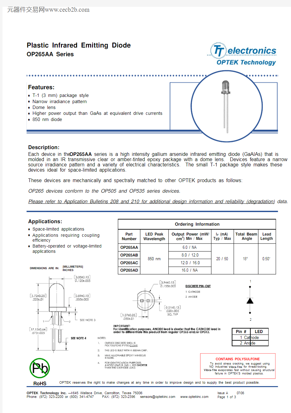
Each device in the OP265AA series is a high intensity gallium arsenide infrared emitting diode (GaAIAs) that is
molded in an IR transmissive clear or amber-tinted epoxy package with a dome lens. Devices feature a narrow
source irradiance pattern and a variety of electrical characteristics. The small T-1 package style makes these devices ideal for space-limited applications.
These devices are mechanically and spectrally matched to other OPTEK products as follows:
OP265 devices conform to the OP505 and OP535 series devices.
Please refer to Application Bulletins 208 and 210 for additional design information and reliability (degradation) data.
INCHES
[MILLIMETERS]
DIMENSIONS ARE IN:
Ordering Information
Part Number LED Peak Wavelength
Output Power (mW/cm 2) Min / Max
I F (mA) Typ / Max Total Beam Angle Lead Length
OP265AA 850 nm
6.0 / NA
20 / 50 18° 0.50”
OP265AB 8.0 / 12.0 OP265AC
12.0 / 16.0 OP265AD
16.0 / NA
Applications:
? Space-limited applications
? Applications requiring coupling
efficiency
? Battery-operated or voltage-limited applications
1
2
Pin # LED
1 Cathode
2 Anode
CONTAINS POLYSULFONE
To avoid stress cracking, we suggest using ND Industries’ Vibra-Tite for thread-locking. Vibra-Tite evaporates fast without causing structural
failure in OPTEK'S molded plastics.
OP265AA Series
Electrical Characteristics (T A = 25°C unless otherwise noted)
SYMBOL PARAMETER MIN TYP MAX UNITS TEST CONDITIONS Input Diode
E E (APT)
mW/cm 2 Apertured Radiant Incidence
OP265AA OP265AB OP265AC OP265AD
5.50 7.50 11.50 15.50
- - - -
-
12.5 16.5 -
I F = 20 mA
Aperture = 0.081” diameter Distance = 0.590” from seating surface to aperture surface
V F Forward Voltage - - 1.80 V I F = 20 mA I R Reverse Current
- 10 - μA V R = 10 V λP Wavelength at Peak Emission - 850 - nm
I F = 10 mA
?λP /?T Spectral Shift with Temperature - ±0.18 - nm/°C I F = Constant θHP Emission Angle at Half Power Points - 18 - Degree I F = 20 mA t r Output Rise Time - 10 - ns I F(PK)=100 mA, PW=10 μs, D.C.=10.0%
t f
Output Fall Time
-
10
-
ns
Notes:
1. RMA flux is recommended. Duration can be extended to 10 second maximum when flow soldering. A maximum of 20 grams force
may be applied to the leads when soldering. 2. Derate linearly at 1.33 mW/° C above 25° C.
3. E E(APT) is a measurement of the average apertured radiant incidence upon a sensing area 0.081” (2.06 mm) in diameter, perpendicular
to and centered on the mechanical axis of the lens and 0.590” (14.99 mm) from the measurement surface. E E(APT) is not necessarily uniform within the measured area.
Absolute Maximum Ratings (T A =25°C unless otherwise noted)
Storage and Operating Temperature Range -40o C to +100o C
Reverse Voltage
2.0 V Continuous Forward Current
50 mA Peak Forward Current (1 μs pulse width, 300 pps)
3.0 A Lead Soldering Temperature [1/16 inch (1.6 mm) from case for 5 seconds with soldering iron] 260° C (1) Power Dissipation
100 mW (2)
OP265AA Series
OP265 (AA, AB, AC, AD)
Forward Voltage vs Forward Current vs
Temperature
T y p i c a l F o r w a r d V o l t a g e (V )
Optical Power vs I F vs Temperature
0.0
0.5
1.0
1.5
2.0
2.5
3.0
3.5
10
20
30
40
50
60
70
80
90
100
Forward Current I F (mA)
N o r m a l i z e d O p t i c a l P o w e r
Relative Radiant Intensity vs. Angular
Displacement
-20
-15
-10
-5
5
10
15
20
Angular Displacement (Degrees)
R e l a t i v e R a d i a n t I n t e n s i t y
1
2
3
4
5
6
0.2 ''0.4 ''0.6 ''0.8 '' 1.0 '' 1.2 '' 1.4 '' 1.6 '' 1.8 '' 2.0 ''
Distance (inches)N o r m a l i z e d O u t p u t P o w e r