Design of High-Efficiency Diffraction Gratings Based on Rigorous Coupled-Wave Analysis for
CHIN.PHYS.LETT.
Vol.25,No.5(2008)1684
Design of High-E?ciency Di?raction Gratings Based on Rigorous Coupled-Wave
Analysis for 800nm Wavelength ?
KONG Wei-Jin( )1??,YUN Mao-Jin( )1,LIU Shi-Jie( )2,JIN Yun-Xia( )2,
FAN Zheng-Xiu( )2,SHAO Jian-Da( )2
1
College of Physics Science,Qingdao University,Qingdao 266071
2
Shanghai Institute of Optics and Fine Mechanics,Chinese Academy of Sciences,Shanghai 201800
(Received 18January 2008)
We report on the design of a high di?raction e?ciency multi-layer dielectric grating with wide incident angle and broad bandwidth for 800nm.The optimized grating can achieve >95%di?raction e?ciency in the ?rst order at an incident angle of 5?from Littrow and a wavelength from 770nm to 830nm,with peak di?raction e?ciency of >99.5%at 800nm.The electric ?eld distribution of the optimized multi-layer dielectric grating within the gratings ridge is 1.3times enhancement of the incidence light,which presents potential high laser resistance ability.Because of its high-e?ciency,wide incident,broad bandwidth and potential high resistance ability,the multi-layer dielectric grating should have practical application in Ti:sapphire laser systems.
PACS:42.40.Eq,42.40.Lx,78.20.?e
In the past years,chirped-pulse ampli?cation (CPA)has enabled the attainment of high average power laser pulse with femtosecond.[1]Among the technologies of CPA,gratings used to compress and stretch the laser pulse should have high e?ciency and high laser resistance.[2]Though traditional gold-coated gratings can achieve a di?raction e?ciency of 95%,those gratings have an inherently low dam-age threshold owing to their absorbing character.[3]This limitation led to the development of multi-layer dielectric gratings (MDGs)by Sychugov in the early 1990s.[4]To improve the di?raction e?-ciency and laser-induced damage threshold,many re-searchers have devoted to the optimization of the grating structure,holographic exposing and etching methods.[5?9]With the development of high average power Ti:sapphire based lasers,new speci?cations of multi-layer dielectric gratings such as the wavelength,incidence angle,pulse width,laser induced damage must be considered further.Many methods such as metal-dielectric resonant e?ect and multi-layer di-electric di?raction e?ect have been adopted to the design and optimization of the grating working at 800nm.[10,11]
In this Letter,we develop an optimized design of multi-layer dielectric grating,which is used in a Ti:sapphire laser system to obtain the high aver-age power and ultra-short pulse.To achieve high di?raction e?ciency,high laser resistance ability and su?cient manufacturing latitude,the grating depth and duty cycle are optimized by employing rigorous coupled-wave analysis (RCWA).
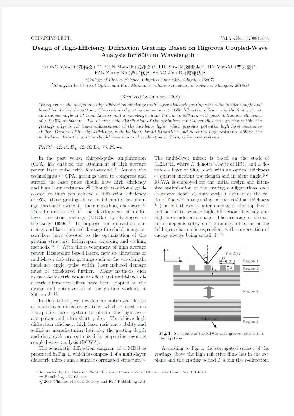
The schematic di?raction diagram of a MDG is presented in Fig.1,which is composed of a multi-layer dielectric mirror and a surface corrugated structure.[9]
The multi-layer mirror is based on the stack of (H2L)n H,where H denotes a layer of HfO 2and L de-notes a layer of SiO 2,each with an optical thickness of quarter incident wavelength and incident angle.[12]RCWA is employed for the initial design and inten-sive optimization of the grating con?gurations such as groove depth d ,duty cycle f de?ned as the ra-tio of line-width to grating period,residual thickness h (the left thickness after etching of the top layer)and period to achieve high di?raction e?ciency and high laser-induced damage.The accuracy of the so-lution depends solely on the number of terms in the ?eld space-harmonic expansion,with conservation of energy always being satis?ed.[13]
Fig.1.Schematic of the MDGs with grooves etched into the top layer.
According to Fig.1,the corrugated surface of the gratings above the high re?ective ?lms lies in the x -z plane and the grating period T along the x -direction.
?Supported by the National Natural Science Foundation of China under Grant No 10704079.
??
Email:kwjsd@https://www.360docs.net/doc/b314703906.html,
c
2008Chinese Physical Society and IOP Publishing Ltd
No.5KONG Wei-Jin et al.1685 For analysing,the MDG needs to be divided into N
layers along z-direction such as air,corrugate surface,
layers of high re?ective?lm,substrate and outgoing
layer(air).Each dielectric layer can be regarded as a
grating with the same period as the corrugated sur-
face layer and a duty cycle of1.When a plane wave
of TE mode(electric?eld perpendicular to incident
plane)is obliquely incident upon the grating,the re-
?ected di?raction e?ciency of the?rst order can be
obtained by using RCWA.[14]
For a general multi-layer dielectric grating,the
several parameters are connected with its perfor-
mance:wavelength,incident angle,line density,
groove depth,duty cycle,and residual thickness.In this study,the wavelength is preferred as800nm for the Ti:sapphire laser system,the grating period of 561.7nm(1780lines/mm)is preferred for facilitating fabrication and the corresponding?rst order Littrow angle is45.4?.We consider an MDG with the cor-rugated surface etched into HfO2on the top of the multi-layer dielectric?lms.Figure
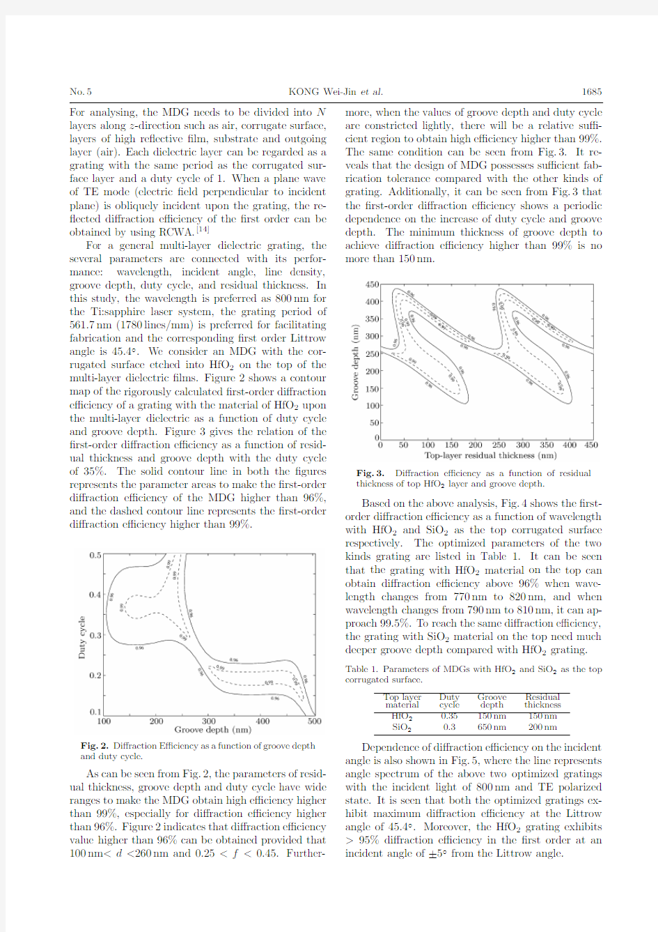
2shows a contour map of the rigorously calculated?rst-order di?raction e?ciency of a grating with the material of HfO2upon the multi-layer dielectric as a function of duty cycle and groove depth.Figure3gives the relation of the ?rst-order di?raction e?ciency as a function of resid-ual thickness and groove depth with the duty cycle of35%.The solid contour line in both the?gures represents the parameter areas to make the?rst-order di?raction e?ciency of the MDG higher than96%, and the dashed contour line represents the?rst-order di?raction e?ciency higher than99%.
Fig.2.Di?raction E?ciency as a function of groove depth and duty cycle.
As can be seen from Fig.2,the parameters of resid-ual thickness,groove depth and duty cycle have wide ranges to make the MDG obtain high e?ciency higher than99%,especially for di?raction e?ciency higher than96%.Figure2indicates that di?raction e?ciency value higher than96%can be obtained provided that 100nm Fig.3.Di?raction e?ciency as a function of residual thickness of top HfO2layer and groove depth. Based on the above analysis,Fig.4shows the?rst-order di?raction e?ciency as a function of wavelength with HfO2and SiO2as the top corrugated surface respectively.The optimized parameters of the two kinds grating are listed in Table1.It can be seen that the grating with HfO2material on the top can obtain di?raction e?ciency above96%when wave-length changes from770nm to820nm,and when wavelength changes from790nm to810nm,it can ap-proach99.5%.To reach the same di?raction e?ciency, the grating with SiO2material on the top need much deeper groove depth compared with HfO2grating. Table1.Parameters of MDGs with HfO2and SiO2as the top corrugated surface. Top layer Duty Groove Residual material cycle depth thickness HfO20.35150nm150nm SiO20.3650nm200nm Dependence of di?raction e?ciency on the incident angle is also shown in Fig.5,where the line represents angle spectrum of the above two optimized gratings with the incident light of800nm and TE polarized state.It is seen that both the optimized gratings ex-hibit maximum di?raction e?ciency at the Littrow angle of45.4?.Moreover,the HfO2grating exhibits >95%di?raction e?ciency in the?rst order at an incident angle of±5?from the Littrow angle. 1686KONG Wei-Jin et al.Vol.25 From the above analysis,we can see that the HfO2grating has wider bandwidth,wider angle de-pendence,su?cient manufacturing latitude.Thus the HfO2layer is preferred as the top corrugated surface to obtain excellent performance as using in the system of Ti:sapphire laser systems. Fig.4.Wavelength performance of MDGs with HfO2and SiO2as the top corrugated surface. Fig.5.Angular spectrum of the two optimized grating with HfO2and SiO2as the top layer. Fig.6.Near-?eld distribution of the optimized HfO2 grating with the parameters in Table1. Previous study shows that laser-induce damage threshold of MDGs is closely connected with the elec-tric?eld enhancement in the corrugated surface.[15] Whereas the electric?eld distribution is greatly de-pendent on the combination of the parameters such as groove depth,duty cycle and residual thickness.[16] The optimized HfO2MDG with the grating depth and duty cycle being150nm and0.35can achieve di?rac-tion e?ciency of99.5%as can be seen from Fig.4.The electric enhancement in the HfO2grating is shown in Fig.6,where the maximum value of electric?eld in the grating is only1.3times the value of the incident elec-tric?eld.It indicates that the above optimized design of MDGs has potential high laser resistance ability. In conclusion,we have designed a multi-layer di-electric grating bearing wide angle spectrum depen-dence,broad bandwidth(60nm)and high e?ciency (99.5%)with the corrugated surface etched in the top HfO2layer,which works at800nm wavelength and Lit-trow angle incident condition.The optimized grating exhibits less near-?eld enhancement(1.3times)with rather shallow groove depth(150nm).Further study should focus on the art to manufacture the designed gratings.Therefore the designed grating would have an extensive application in the Ti:sapphire laser sys-tems to obtain the high average power and ultra-short pulse. References [1]Wang C,Leng Y X,Liang X Y,Zhang C M and Xu Z Z 2005Chin.Phys.Lett.223091 [2]Koichi Y K and Barty C P2003Opt.Lett.282402 [3]Boyd R D,Britten J A and Decker D E1995Appl.Opt. 341697 [4]Svakhin A A,and Sychugov V A1991Sov.Phys.Tech. Phys.361038 [5]Perry M D,Boyd R D,Britten J A,Decker D,Shore B W and Shannon C1995Opt.Lett.20940 [6]Hehl K,Bischo?J and Mohaupt U1999Appl.Opt.38 6257 [7]Britten J A,Perry M D and Shore B W1996Proc.SPIE 2714511 [8]Shore B W and Perry M D1997J.Opt.Soc.Am.A14 1124 [9]Oliver J B,Kessler T J,and Huang H2005Proc.SPIE 599159911A1-7 [10]Canova F,Uteza O,Chambaret J P,Flury M,Tonchev S, Fechner R and Parrianx O2007Opt.Express1515324 [11]Kong W J,Liu S J,Shen J,Shen Z C,Shao J D and Fan Z X2005Acta.Phys.Sin.551143 [12]Kong W J,Shen Z C,Shen J,Shao J D and Fan Z X2005 Optik116325 [13]Moharam M G,Eric B G and Drew A P1995J.Opt.Soc. Am.A121068 [14]Moharam M G,Drew A P and Eric B G1995J.Opt.Soc. Am.A121077 [15]Kong W J,Shen Z C,Shen J,Shao J D and Fan Z X2005 Chin.Phys.Lett.221757 [16]Liu S J,Shen Z C,Kong W J,Shen J,Deng D X,Zhao Y A,Shao J D and Fan Z https://www.360docs.net/doc/b314703906.html,mun.26750