VW01045_EN_2004-03-01
Confidential. All rights reserved. No part of this document may be transmitted or reproduced without the prior written permission of a Standards Department of the Volkswagen Group.
Parties to a contract can only obtain this standard via the responsible procurement department.
? VOLKSWAGEN AG
T h e E n g l i s h t r a n s l a t i o n i s b e l i e v e d t o b e a c c u r a t e . I n c a s e o f d i s c r e p a n c i e s t h e G e r m a n v e r s i o n s h a l l g o v e r n .
Page 2
VW 010 45: 2004-03
2 Designation
The threaded through-hole for tolerance zone 6H shall be indicated in drawings as follows: Example:
Threaded through-hole VW 010 45 – M12 x 1.5
If a different tolerance zone is used, this must be indicated after the thread designation. If the thread is formed, “formed” shall follow the thread designation. 3
Geometric dimensions
See Figure 1 and Table 1. 3.1
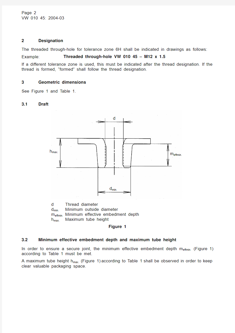
Draft
d Thread diameter
d min. Minimum outsid
e diameter
m effmin. Minimum effective embedment depth h max.
Maximum tube height
Figure 1
3.2
Minimum effective embedment depth and maximum tube height
In order to ensure a secure joint, the minimum effective embedment depth m effmin. (Figure 1) according to Table 1 must be met.
A maximum tube height h max. (Figure 1) according to Table 1 shall be observed in order to keep clear valuable packaging space.
d
h max.
m effmin.
d min.
Page 3
VW 010 45: 2004-03 Table 1 – Minimum effective embedment depths
Minimum tensile strength
R m *)
Minimum effective
embedment depth for screws
of property classes ≤ 10.9
Maximum tube height
h max.
[MPa][mm][mm]
< 400 1.5 x d 2.0 x d ≥ 400 to ≤ 530 1.3 x d 1.8 x d
*) Minimum tensile strength in initial condition (unshaped sheet condition)
In case of fine-pitch threads, the embedment depth shall be increased by 20%, see VW 011 10.
3.3 Outside diameter of the threaded through-hole
In order to ensure the possibility of using a threaded insert made of wire according to DIN 8140-1 in case of repair (defective thread), the minimum outside diameter d min. (Figure 1) must be selected such that the repaired thread also passes the tests of the mechanical properties listed under Section 4.
4 Tests
4.1 Testing force test
The testing forces according to Table 2 apply when the testing force test according to DIN EN 20 898-2 and DIN EN ISO 898-6 is performed.
Table 2 – Testing forces
Thread Testing force
[N]
M5 16300
M6 23100
M8 42500
M10 67300
M12 x 1.5 105700
M14 x 1.5 150000
M16 x 1.5 200400
4.2 Overload test
An overload test must be performed. The result is positive only if a fracture of the screw occurs in the free stressed thread area or in the shank. This test shall be documented by recording a torque/angle of rotation diagram (called a breakaway diagram). The test setup shall be coordinated with the developer and documented.
After the test, it must be possible to screw a new screw into the tested nut thread by hand.
Page 4
VW 010 45: 2004-03
4.3 Evaluation of the internal findings
4.3.1
Graphical representation of the fiber course after shaping
Microsections are taken of threaded through-holes that have been cut through the center to detect wrinkles in the microstructure. Wrinkles result from improper design of the individual shaping stages and can cause component failure. The supplier must therefore prepare and supply microsections no later than upon first sampling as well as during standard production in case of a change in the shaping sequence or a material batch or tooling change. 4.3.2
Type of thread
The thread can be produced by cutting or forming (Figures 2 and 3).
Figure 2 – Thread produced by cutting
Figure 3 – Formed thread
The quality of the thread shall be documented according to the tests listed under Section 4 and according to trueness to gage.
The minor thread diameter before thread production shall be documented by the manufacturer and proven in case of complaint. 4.3.3
Workmanship of the threaded through-hole
Transverse flaws in the transitional arc between the threaded through-hole and the sheet that interrupt the fiber course are not permitted.
Wrinkles that run on the surface are to be classified as non-critical.
Page 5
VW 010 45: 2004-03
4.4 Repeat assembly test
A 10 x repeat assembly in the original connection, with the tightening parameters specified in Table 3 or specified separately for the individual threaded connection and a clamping length of (1 to 4) x d, shall be performed.
The following conditions apply:
The thread must be filled with hot wax (only if the nut is also waxed in the original connection,
e.g., AKR 335F10 or AKR 336); otherwise, possible contamination of the nut by grease, oil or
similar materials must be considered if there is a risk that these are a factor in the production process or customer service.
New original screws must be used in each case.
The original components must be fastened; alternative components must be approved by the responsible development department.
Table 3 – Tightening parameters
Thread
Tightening specification
M5 5 Nm + 90°
M610 Nm + 90°
M820 Nm + 90°
M1050 Nm + 90°
M12 x 1.590 Nm + 90°
M14 x 1.5150 Nm + 90°
M16 x 1.5180 Nm + 90°
The result can be evaluated as positive only if
no failure, e.g., stripping of the nut thread, deformation of the threaded plate, etc., occurs, a new screw can be easily screwed in after testing is completed.
Page 6
VW 010 45: 2004-03
5 Referenced standards*)
DIN 8140-1 Wire Thread Inserts for ISO Metric Screw Threads –
Part 1: Dimensions and Technical Delivery Conditions
DIN EN 20 898-2 Mechanical Properties of Fasteners –
Part 2: Nuts with Specified Proof Load Values; Coarse Thread
DIN EN ISO 898-6 Mechanical Properties of Fasteners –
Part 6: Nuts with Defined Testing Forces; Fine-Pitch Thread
VW 116 10 Metric ISO Threads; Limit Dimensions for Medium Tolerance Class;
Male 6g, Female 6H
VW 116 11 Metric ISO Threads; Limit Dimensions with Surface Protection Layer for Medium Tolerance Class 6g/6H
VW 116 13 Metric ISO Threads; Limit Dimensions for Fine Tolerance Class; Male 4h, Female 5H
VW 116 15 Metric ISO Thread; Limit Dimensions with Protective Coating for Coarse Tolerance Class (8g/7H)
VW 011 10 Threaded Joints; Design, Assembly and Process Assurance
VW 011 78 Limit Dimensions for Ridged Thread; Metric ISO Thread
*) In this section, terminological inconsistencies may occur as the original titles are used.