SGL41-20中文资料

BYM13-20 THRU BYM13-60SGL41-20 THRU SGL41-60
SURFACE MOUNT SCHOTTKY BARRIER RECTIFIER
Reverse Voltage - 20 to 60 Volts Forward Current - 1.0 Ampere
FEATURES
? Plastic package has carries Underwriters Laboratory Flammability Classifications 94V-0? For surface mounted applications
? Metal silicon junction, majority carrier conduction ? High surge capability
? Low power loss, high efficiency
? High current capability, low forward voltage drop
? For use in low voltage, high frequency inverters, free wheeling and polarity protection applications ? Guardring for overvoltage protection ? High temperature soldering guaranteed:250°C/10 seconds at terminals
MECHANICAL DATA
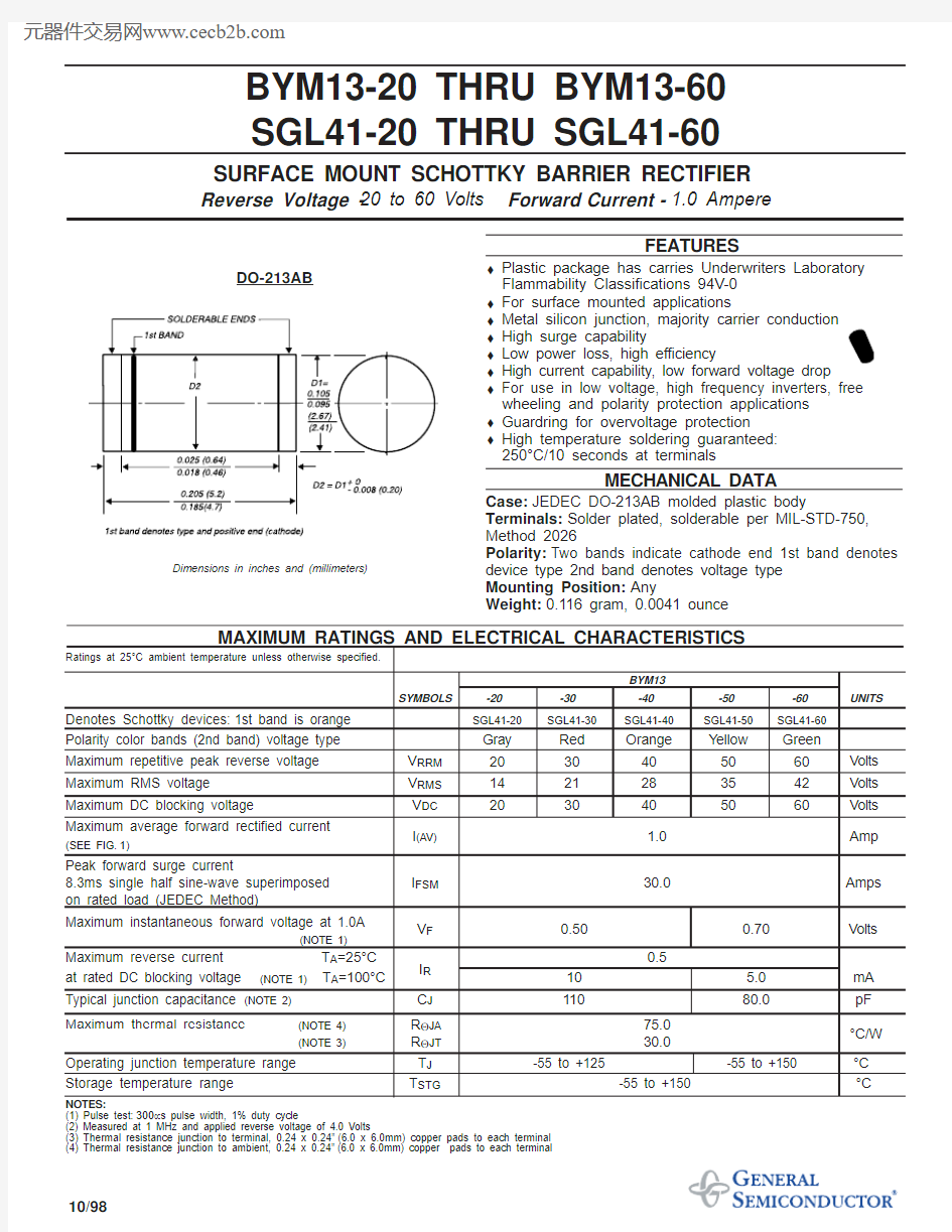
Case:JEDEC DO-213AB molded plastic body
Terminals:Solder plated, solderable per MIL-STD-750,Method 2026
Polarity:Two bands indicate cathode end 1st band denotes device type 2nd band denotes voltage type Mounting Position:Any
Weight:0.116 gram, 0.0041 ounce
MAXIMUM RATINGS AND ELECTRICAL CHARACTERISTICS
Ratings at 25°C ambient temperature unless otherwise specified.
BYM13
SYMBOLS
-20-30-40-50-60UNITS
Denotes Schottky devices:1st band is orange SGL41-20
SGL41-30
SGL41-40
SGL41-50
SGL41-60
Polarity color bands (2nd band) voltage type Gray
Red Orange Y ellow Green Maximum repetitive peak reverse voltage V RRM 2030405060Volts Maximum RMS voltage V RMS 1421283542Volts Maximum DC blocking voltage
V DC 20
30
4050
60
Volts Maximum average forward rectified current
(SEE FIG.1)
I (AV) 1.0Amp Peak forward surge current
8.3ms single half sine-wave superimposed I FSM 30.0
Amps
on rated load (JEDEC Method)
Maximum instantaneous forward voltage at 1.0A
V F 0.50
0.70Volts (NOTE 1)
Maximum reverse current T A =25°C 0.5
at rated DC blocking voltage (NOTE 1)
T A =100°C
I R 10 5.0mA Typical junction capacitance (NOTE 2)
C J
110
80.0
pF Maximum thermal resistance
(NOTE 4)R ΘJA 75.0(NOTE 3)
R ΘJT 30.0
°C/W
Operating junction temperature range T J -55 to +125
-55 to +150
°C Storage temperature range
T STG
-55 to +150
°C
NOTES:
(1) Pulse test:300μs pulse width, 1% duty cycle
(2) Measured at 1 MHz and applied reverse voltage of 4.0 Volts
(3) Thermal resistance junction to terminal, 0.24 x 0.24”(6.0 x 6.0mm) copper pads to each terminal (4) Thermal resistance junction to ambient, 0.24 x 0.24”(6.0 x 6.0mm) copper pads to each terminal
10/98
DO-213AB
Dimensions in inches and (millimeters)