A Wearable Smartphone-Based Platform for
A Wearable Smartphone-Based Platform for Real-Time Cardiovascular Disease Detection Via Electrocardiogram Processing
Joseph J.Oresko,Student Member,IEEE,Zhanpeng Jin,Student Member,IEEE,Jun Cheng, Shimeng Huang,Yuwen Sun,Heather Duschl,and Allen C.Cheng,Member,IEEE
Abstract—Cardiovascular disease(CVD)is the single leading cause of global mortality and is projected to remain so.Cardiac arrhythmia is a very common type of CVD and may indicate an increased risk of stroke or sudden cardiac death.The ECG is the most widely adopted clinical tool to diagnose and assess the risk of arrhythmia.ECGs measure and display the electrical activity of the heart from the body surface.During patients’hospital visits,how-ever,arrhythmias may not be detected on standard resting ECG machines,since the condition may not be present at that moment in time.While Holter-based portable monitoring solutions offer 24–48h ECG recording,they lack the capability of providing any real-time feedback for the thousands of heart beats they record, which must be tediously analyzed of?ine.In this paper,we seek to unite the portability of Holter monitors and the real-time process-ing capability of state-of-the-art resting ECG machines to provide an assistive diagnosis solution using smartphones.Speci?cally,we developed two smartphone-based wearable CVD-detection plat-forms capable of performing real-time ECG acquisition and dis-play,feature extraction,and beat classi?cation.Furthermore,the same statistical summaries available on resting ECG machines are provided.
Index Terms—Arrhythmia detection,cardiovascular disease (CVD)detection,ECG processing,machine learning,smartphone, windows mobile.
I.I NTRODUCTION
C ARDIOV ASCULAR disease(CVD)is the single leading
cause of death in both developed and developing coun-tries,and encompasses a variety of cardiac conditions,includ-ing heart attack and hypertension.According to the American Heart Association,in the United States alone,80000000peo-ple are estimated to have one or more forms of CVD and nearly
Manuscript received July21,2009;revised October22,2009and February 3,2010.First published April12,2010;current version published June3,2010. This research was supported by Microsoft Research(Cell Phone as a Platform for Healthcare Award)and the National Science Foundation grant(NSF#0832990) awarded to Allen C.Cheng.
J.J.Oresko,Z.Jin,J.Cheng,S.Huang,Y.Sun,and H.Duschl are with the Department of Electrical and Computer Engineering,University of Pittsburgh,Pittsburgh,PA15261USA(e-mail:jjo5@https://www.360docs.net/doc/da153996.html,;zhj6@https://www.360docs.net/doc/da153996.html,; juc25@https://www.360docs.net/doc/da153996.html,;shh61@https://www.360docs.net/doc/da153996.html,;yus25@https://www.360docs.net/doc/da153996.html,;hld11@https://www.360docs.net/doc/da153996.html,).
A.C.Cheng is with the Departments of Electrical and Computer Engineer-ing,Computer Science,Bioengineering,and Neurological Surgery,University of Pittsburgh,Pittsburgh,PA15261USA(e-mail:acc33@https://www.360docs.net/doc/da153996.html,).
Color versions of one or more of the?gures in this paper are available online at https://www.360docs.net/doc/da153996.html,.
Digital Object Identi?er10.1109/TITB.2010.20478652400Americans die of CVD each day[1].Cardiac arrhythmia, de?ned as abnormal heart rhythms,is a very common type of CVD and is thought to be responsible for most of the sudden cardiac deaths that occur every year.
The most common test for a cardiac arrhythmia is an ECG. The ECG measures the electrical impulses of the heart via elec-trodes on the skin’s surface.However,it is dif?cult to diagnose many arrhythmias with a standard resting ECG,because it can only provide a snapshot of the patient’s cardiovascular activity in time.An intermittent arrhythmia can go unnoticed,and physi-cians must rely on self-monitoring and symptoms reported by patients to support their?nal diagnosis.In some cases,ambu-latory recording of ECG data,collected over extended periods of time,may be taken in an attempt to acquire data during an occurrence of an intermittent arrhythmia.However,existing so-lutions for this type of recording are limited.Although they can lead to a diagnosis and therapy that may greatly improve the quality of life for the patient,they can be inconvenient for both the patient and the physician.
Three types of ECG solutions are possible,which are as fol-lows:1)those that can store information to be diagnosed of?ine after data collection is complete;2)those that use remote con-nections to provide real-time diagnosis via a separate server; and3)those that perform real-time diagnosis within the de-vice itself.Among the?rst type of systems,Holter monitors and event recorders stand out,such as GE’s SEER(GE Health-care,Waukesha,WI),Philips’s DigiTrack(Philips Healthcare, Andover,MA),and Midmark’s IQmark(Midmark Corpora-tion,Versailles,OH),among others.These devices only provide recording and monitoring capabilities and no real-time classi?-cation of ECGs because the classi?cation is performed of?ine. The second type utilizes telemedical functionalities via a remote real-time monitoring system[2]–[4].Most of them make use of mobile phones/personal digital assistants(PDAs)to collect the ECG data and send them to a monitoring center,where the anal-ysis and classi?cation are performed,thus depriving the user of real-time feedback.For the third type of systems,researchers have proposed some intermediate level of local real-time clas-si?cation,such as the classi?cation of heart beats,by using up-to-date smartphones or PDAs[5]–[8],but these do not provide a complete CVD diagnosis solution.The continued development of powerful microprocessors allows researchers to develop ap-plications for these handheld devices that deliver comparable performance to that of a desktop computer only a few years ago.
1089-7771/$26.00?2010IEEE
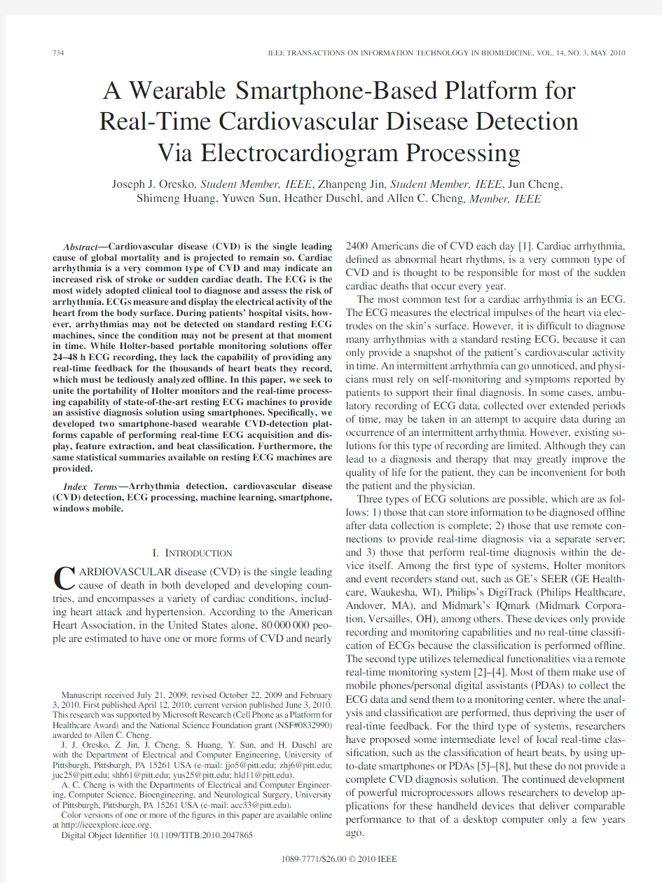
Fig.1.HeartToGo experimental prototype consisting of an Amoi Windows Mobile5Smartphone and a single-channel Alive ECG sensor.
With people becoming more active in monitoring their own health via assistive diagnosis platforms,there exists a need to im-plement a real-time,user friendly CVD monitoring system.We seek to provide the user with an enriched interface with which they can monitor their ECG in real time.The contribution of this research lies on in-depth analysis of ECG signals and the development of a portable smartphone-based CVD monitoring and assistive diagnosis platform.To this end,we implemented two smartphone-based wearable CVD-detection platforms:a machine-learning and rapid prototyping platform and a plug-in-based GUI platform.Each performs real-time ECG acquisition and display,feature extraction,and beat classi?cation.Further-more,the same statistical summaries available on resting ECG machines are provided,which include:RR,P,and QRS dura-tions;PR,QT,and QTc intervals;and average,high,and low heart rates.
II.S YSTEM D ESIGN F RAMEWORK
The system design framework for the machine-learning and plug-in-based GUI platform is presented in this section.Incor-porating machine learning into the platform is an effective way to introduce self-adaptable ECG processing and CVD detection to account for the user’s unique physiological characteristics, while a plug-in-based platform allows for new disease-detection rules to be integrated without changing the main program.The prototype consists of a Windows Mobile Smartphone and a single-channel Alive ECG sensor,as shown in Fig.1.
A.Plug-In-Based GUI Platform
1)Data Acquisition:To acquire real-time ECG signals,we employed Alive Technology’s(Alive Technologies Pty.Ltd., Robina,Qld.,Australia)state-of-the-art wireless ECG heart monitor,which is a lightweight(60g with battery),low-power (60h of operation with continuous wireless transmission)wear-able single-channel ECG-sensing device capable of recording 3008-bit samples per second.It is equipped with a class-1 Bluetooth transmitter,which can send its data to smartphones or other wireless devices.Also,the monitor is equipped with a three-axis accelerometer.Furthermore,the ECG signal from the monitoring session can be recorded to a secure digital(SD)
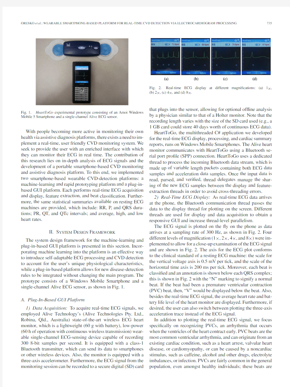
card Fig. 2.Real-time ECG display at different magni?cations:(a)1×, (b)2×,(c)4×,and(d)8×.
that plugs into the sensor,allowing for optional of?ine analysis by a physician similar to that of a Holter monitor.Note that the recording length varies with the size of the SD card used(e.g.,a 1GB card could store40days worth of continuous ECG data). HeartToGo,the multithreaded C#application we developed for the real-time ECG display,processing,and cardiac summary reports,runs on Windows Mobile Smartphones.The Alive heart monitor communicates with HeartToGo using a Bluetooth se-rial port pro?le(SPP)connection.HeartToGo uses a dedicated thread to process the incoming Bluetooth data stream,which is made up of variable length packets containing both ECG data samples and acceleration data samples.Once the input data is read,parsed,and veri?ed,thread delegates manage the shar-ing of the new ECG samples between the display and feature-extraction threads in order to avoid cross-threading errors.
2)Real-Time ECG Display:As real-time ECG data arrives at the phone,the Bluetooth communication thread passes the data to the display thread for plotting on the screen.Different threads are used for display and data acquisition to obtain a responsive GUI and increase thread-level parallelism.
The ECG signal is plotted on the?y on the phone as data arrives at a sampling rate of300Hz,as shown in Fig.2.Four different levels of magni?cation(1×,2×,4×,and8×)were im-plemented to allow for a close-up examination of the ECG signal and are shown in Fig.2.The axis for the ECG plot conforms to the clinical standard of a resting ECG machine:the scale for the vertical voltage axis is0.5mV per tick,and the scale of the horizontal time axis is200ms per tick.Moreover,each beat is classi?ed and an annotation is shown below each QRS complex; this is shown in Fig.2with the“N”marking to signify a normal beat.If the beat had been a premature ventricular contraction (PVC)beat,then,“V”would be displayed below the beat.Also, besides the real-time ECG signal,the average heart rate and bat-tery life level of the heart monitor are displayed.Furthermore,if desired,the user can also switch between plotting the three-axis acceleration trace instead of the ECG signal.
In addition to plotting the real-time ECG signal,we focus speci?cally on recognizing PVCs,an arrhythmia that occurs when the ventricles of the heart contract early.PVC beats are the most common ventricular arrhythmia,and can originate from an existing cardiac condition,such as a heart arrest,valvular heart disease,or cardiomyopathy,or can be caused by a noncardiac stimulus,such as caffeine,alcohol and other drugs,electrolyte imbalances,or infection.PVCs are fairly common in the general population,even amongst healthy individuals;these beats are
Fig.3.ECG feature-extraction work?ow.
found in approximately60%of healthy people in ambulatory ECGs[9].This prevalence makes PVC a very suitable candidate for the?rst-classi?ed CVD of our functional prototype.
3)Feature Extraction and Classi?cation:Feature extraction and classi?cation are implemented on the smartphone as a sep-arate dynamic-linked library(dll)from the main HeartToGo application and runs on its own thread.Due to the computation-ally intensive math required,it is written in C++to improve execution speed,as opposed to C#,which was used for the GUI, since it has a streamlined implementation in Windows Mobile using https://www.360docs.net/doc/da153996.html, https://www.360docs.net/doc/da153996.html,ing this approach,different dll plug-ins can be created for different CVDs without changing the main program,which is responsible for data acquisition and display.
Fig.3shows the work?ow for ECG feature extraction.To get all the features of the ECG,the?rst step is to detect the QRS. We utilize the algorithm proposed by Hamilton[10]to get the onset and offset of each QRS.The implementation details can be found in Section II-B when we describe the machine-learning framework.The original algorithm in[10]used a bandpass(BP)?nite-impulse response(FIR)?lter to remove noise,which is also mentioned in[11]and[12].In our design,to identify the Gibbs rings in the?ltered results,we add an averaging?lter that calculates the average value of every six neighbor points. The averaging?lter also helps us to judge the polarity of the P and T waves.Although we can exclude most of the obvious Gibbs rings,we may not?nd the main peaks of the P or T waves in the?ltered result directly,if their amplitudes are too low.Therefore,we need to know the polarity of the P and T waves before identifying their locations.First,we have to determine the isoelectric region before and after the QRS in order to?nd the reference point for the P and T waves.Then,we look for the nearest local maximum and minimum points before the reference P wave,as well as the nearest local maximum and minimum points after the T wave.By adding a threshold,we can judge the polarity of the P and T waves.Finally,we can get the start and end of the P wave and the end of the T wave.
What https://www.360docs.net/doc/da153996.html,parison of the BP FIR?lter result and average?lter result.F(n) is the corresponding BP FIR?lter result,and A(n)is the corresponding average ?lter result.
follows is the justi?cation for choosing a BP FIR?lter and the details of our design.
BP?lters can reduce the baseline wander signi?cantly,but a Gibbs ringing phenomena is introduced into the Q and S waves, which manifests as distortions with an amplitude larger than the P wave[13].However,compared with wavelet?lters,BP?lters can conserve a lot of computational resources,which is espe-cially important for real-time mobile phone systems.Therefore, we propose to identify the Gibbs rings in the?ltered signal by sending the original signal to an averaging?lter and comparing the?lter result A(n)with the BP?lter result F(n)to identify the Gibbs rings from the ECG signals.
Although averaging?lters can remove high-frequency noise without creating Gibbs rings,the drift line still exists.We have to?nd a reference point in the signal and use the local difference of the amplitude of the signal waves to judge the polarity.To?nd the reference point for the P wave,we?rst?nd the isoelectric region in A(n)before the QRS.In this region,the change of the signal amplitude stays in a small area.We choose one point in F(n),which is equal to zero,or close to zero,in this region,as the reference point.Similarly,the isoelectric region is after the QRS,but it may not be a straight line because of the drift line. The change of the slope could stay in a small area.In this region, F(n)should have several points equal to zero,and we choose the one,which is closest to the T wave,as the reference point.Then, we calculate the height difference between the reference point and both the nearest maximum and minimum points in A(n)to judge the polarity of the P and T waves.In this example,the P wave is biphasic,and the T wave is negative.When we get the polarity of the P and T waves,we can easily?nd the onset and offset of the P wave and the end of the T wave in F(n).Fig.4 illustrates these reference points,which were used to identify the P and T waves.
4)Cardiac Summary Reports:The same statistical cardiac summary reports provided by standard resting ECG machines are implemented in HeartToGo.Both cardiac statistics and fea-tures are extracted from the ECG signal in real time.Fig.5(a) shows the cardiac statistics,consisting of the average,high,and low heart rate,and the total number of beats,as well as the number of normal and PVC beats.Fig.5(b)presents the cardiac feature report,which includes the RR duration,P duration,QRS
Fig.5.Cardiac summary reports.(a)Statistics.(b)ECG features.(c)Pop-up alarm message for abnormal beat
occurrences.
Fig.6.Work?ow for streaming ECG data via Bluetooth for heart monitor simulation.
duration,PR interval,QT interval,and QTc interval.Further-more,an alarm is triggered when abnormal beats occur so that the user does not have to continuously monitor the cardiac sum-mary reports.The alarm chosen is a pop-up message warning that an abnormal beat has occurred,as shown in Fig.5(c),and an audible/vibratory noti?cation on the phone to alert the user than an abnormal beat has occurred.
5)Streaming Database Veri?cation:In order to verify the proper functionality of the cardiac summary reports and beat classi?cation algorithm,a virtual heart monitor emulator was created with a PC.Instead of transmitting the user’s ECG data from the Alive heart monitor,the PC transmitted the signal from an ECG database using a Bluetooth dongle paired to the https://www.360docs.net/doc/da153996.html,ing MATLAB,a virtual communication port was established and ECG data was read from a database ?le (e.g.,the MIT-BIH Arrhythmia Database from PhysioNet [14]),packaged,and then,transmitted to the phone.Furthermore,a pause was added;therefore,the packages would arrive at the same sampling rate as the Alive heart monitor.This work?ow is shown in Fig.6.
B.Machine-Learning-Based Platform
1)Data Acquisition:As previously described,we again em-ployed Alive Technology’s wireless ECG heart monitor to ac-quire real-time ECG signals.The connection between Alive’s
monitor and smartphone was established via Bluetooth and the data were acquired in our LabVIEW implementation via an SPP.In order to verify the proper functionality and accuracy of the proposed system,we also emulated the real-time data of heart activities and reported the results based on the widely used MIT-BIH Arrhythmia Database.The MIT-BIH database contains 4830-min ambulatory ECG recordings.The original data ?les were directly stored in the smartphone and a speci?c signal exporter was developed to convert the original “format 212”of MIT-BIH database to a binary format readable by LabVIEW.
2)ECG Feature Extraction:The classical Pan–Tompkins QRS-detection algorithm [11]and its errata were adopted and implemented in our ECG processing system because of its proven sensitivity of 99.69%and positive prediction of 99.77%when evaluated with the MIT-BIH arrhythmia database.
The QRS-detection algorithm consists of a BP ?ltering stage that uses a set of cascaded ?lters.The ?rst two stages consist of a low-pass ?lter with a cutoff frequency at about 11Hz and a gain of 36mV/mV with a ?ltering processing delay of six samples,and a high-pass ?lter with a cutoff frequency of about 5Hz with a unity gain and a processing delay of 16samples.The deriva-tive stage differentiates signals to obtain information about the slope of the QRSs.The squaring stage identi?es the slope of the frequency response curve of the derivative and restricts false positives caused by T waves with higher spectral energy.The moving-window integration stage is used to obtain waveform feature information in addition to the information about the slope and the width of the QRS complex.Finally,the rising edge of the integration waveform corresponds to the desired QRS complex.A ?ducial mark for the QRS complex feature can be represented by the temporal location of the peak of the R wave,which is determined according to the waveform excerpt located within the range of this rising edge.As detailed ear-lier,we ?rst implemented this six-stage QRS-complex-detection framework on a PC test bench in LabVIEW,which successfully reduces the effects of irregular distance between peaks,irregular peak forms,and the presence of a low-frequency component in the ECG due to patient’s breathing.Next,the PC implementa-tion was converted to a smartphone implementation,using the LabVIEW Mobile Module,to allow this fast feature-extraction algorithm to run on a Windows Mobile Smartphone,as illus-trated in Fig.7(a),which shows the ECG signal plotted on the ?y as well as the QRS complex that has been identi?ed.As part of this work-in-progress,we have extended the diagnosis capa-bility to include additional features,such as the RR interval,the QRS width,the R peak,and the beat width.
3)Machine-Learning-Based ECG Classi?cation:Among the numerous machine learning paradigms,we focus on the feedforward multilayer perceptron (MLP)arti?cial neural net-work (ANN),which is one of the best-known techniques used in pattern recognition and classi?cation,time-series modeling,nonlinear control,and system identi?cation.In this study,we exploit potential applications of the MLP structure to perform an important ECG processing task:QRS beat pattern classi?cation,on a state-of-the-art smartphone.
QRS beat classi?cation is a crucial task in ECG diagno-sis,and most existing methods rely highly on various discrete
Fig.7.(a)QRS-complex-detection system using the LabVIEW Mobile Mod-ule.(Top)ECG signal.(Bottom)Identi?ed QRS complex.(b)Initial ANN training(top)red—the target results and white—the predicted results;(bottom) the rms,which was continuously decreased as the training progressed from(b) initial training to(c)gradual re?nement.(d)ECG diagnostic predication system: beats are marked above their respective ECG waves.
signal features extracted or measured from the ECG waveform, such as the cardiac interbeat intervals.In this study,we use the morphologies of the heartbeats rather than their discrete features to detect cardiac abnormalities and identify potential arrhythmia.Given the QRS complex and?ducial information obtained from the feature-extraction stage,the input to the MLP ANN is the original QRS morphological beat pattern with an 11-bit resolution over a10mV range.Each input template con-tains51samples centered on the annotated?ducial mark in the recording,which approximately represents a time segment of150ms;each output is associated with a particular class of arrhythmia conditions.Fig.7(b)and(c)presents two different training phases of our ANN implementation on the smartphone, where the red and white waveforms in the upper window repre-sent the target values and the training values,respectively,and the green line in the lower window depicts the gradually de-creasing training error(the exact value is shown in the text box at the bottom of the GUI)between targets and trained values. It is worth noting that we dynamically rescale the error axis in order to enlarge and show the training performance,since the training errors will become small and negligible as the training progresses compared to the errors in the initial training epochs. It is shown in Fig.7(b)that,during the?rst100training epochs, the training error plunges signi?cantly.After that,the network is gradually tuned to?nd a more optimized set of parameters, as shown in Fig.7(c).Correspondingly,the trained waveform (white)continuously adapts itself and gets closer to the target waveform from Fig.7(b)to(c).Furthermore,the whole training process is guided and assessed by the validation set of inputs using cross-validation strategy[15]that is able to help in pre-venting over?tting.The training process is stopped when the error in a validation set starts growing.However,the error trend of the validation set is not shown in the current GUI due to the additional computation resources required and energy savings considerations.
4)Adaptive ANN-Based Prediction:Compared to tradi-tional approaches,patient-speci?c classi?cation approaches an-alyze the ECG waveform characteristics more precisely on a patient-by-patient basis.Nevertheless,real-time applications of-ten require faster training techniques that can be applied to
the Fig.8.Adaptive patient-speci?c ECG predication diagram.
detector in advance.Thus,we proposed a hybrid adaptive strat-egy,which is more suitable for the real-time mobile environment by utilizing both patient-speci?c information and established ECG medical databases.
As shown in Fig.8,the proposed hybrid training strategy can be broken down into the following steps:
1)using an established ECG database to train the ANN;
2)testing the trained ANN on the prospective user;
3)collecting a new ECG dataset M from this user;
4)dividing this new dataset M into two groups,named A and
B,whose testing errors are,respectively,within or beyond the predetermined threshold;
5)retraining the ANN based on the dataset M combined with
expert’s annotation,or purely based on the dataset A; 6)the individualized ANN can perform more accurate CVD
assessment by accounting for physiological characteristics that are speci?c to the target user.
Starting from a generic ECG processing structure and fol-lowing this adaptive training process,the proposed ANN will be able to classify the end user’s individual ECG data more accurately.
The?nal user interface of the proposed CVD classi?cation and prediction framework is shown in Fig.7(d),where each beat is classi?ed into the normal set or one of the13arrhythmias with the detection result shown above it.In this snapshot,two“N”markers correspond to the normal beats and a PVC is identi?ed as a“P.”
III.I MPLEMENTATION
As previously described,the objective of this research seeks to develop smartphone-based platform technologies for wear-able CVD detection,which are capable of performing real-time ECG acquisition and display,feature extraction,and beat clas-si?cation.To demonstrate the feasibility of this idea and to conduct real-time performance characterization on real devices, we developed two proof-of-concept prototypes to show that the
proposed techniques are applicable for both high-end and low-end smartphones.
A.Plug-In-Based GUI Platform
An Alive Bluetooth ECG heart monitor,an Amoi E72 Microsoft Windows Mobile5Smartphone,MATLAB R2008b (used for initial algorithm creation and validation),and Microsoft Visual Studio2008were utilized in the implemen-tation and testing of our plug-in-based real-time CVD monitor-ing system.The application is multithreaded and is written in C#with a feature-extraction plug-in written in C++.For data acquisition and display threads,C#code was used to take ad-vantage of the ef?cient integration between C#and Windows Mobile.On the other hand,algorithmic code was written in C++to increase execution speed of the algorithms.
B.Machine-Learning-Based Platform
An Alive Bluetooth ECG heart monitor and an HTC Microsoft Windows Mobile6Smartphone were utilized in the creation of the machine-learning platform.MATLAB R2008b was utilized to develop and verify our ANN-based ECG processing and CVD classi?cation algorithms prior to converting to LabVIEW.Next,
a platform making use of the LabVIEW Mobile Module(version
8.5),which allows a smartphone to run a LabVIEW binary executable,was developed to deploy the veri?ed algorithms onto the Windows Mobile Smartphone to assess their real-time performance in the target mobile environment.
IV.R ESULTS
Both of?ine and online veri?cation of the algorithms was performed using the MIT-BIH database.In particular,this paper proposes and uses the novel streaming of the MIT database to the smartphone for real-time veri?cation.This allows us to verify the detection of arrhythmias that we could not otherwise detect using normal subjects wearing a heart monitor.To the best of our knowledge,this streaming-based veri?cation technique for CVD detection on smartphone is new.
Furthermore,the machine-learning platform investigated 5421QRS complex templates,which cover the normal beats and four arrhythmia conditions from the MIT-BIH arrhythmia database.To estimate the classi?cation accuracy,we adopted the three-way cross-validation method that is designed to minimize the variations due to the random sampling of?nite-size data samples[16].We partitioned each class of the dataset randomly into three disjoint subsets of approximately equal size denoted by trial A,trial B,and trial C.The training and testing were performed three times each with each one of the three subsets as the training set and the other two as the testing sets.We did such partitioning using MATLAB and the details are summarized in Table I.
We performed the experiment in which a51-30-5MLP ANN structure,based on the structure established for ECG signal de-tection and classi?cation in[16]was used to classify all beats into?ve classes.Table II summarizes the results.A predic-tion accuracy of greater than90%was achieved,except for the
TABLE I
D ISTRIBUTION OF S AMPLES IN
E ACH P
ARTITION
TABLE II
P REDICATION A CCURACY OF N ORMAL AND F OUR A BNORMAL B EATS
(U NIT IN P ERCENTAGE
)
81%prediction accuracy for fusion of paced and normal beat (PFUS),which could be attributed to the varying morphologies of fusion complexes,which change depending on the portion of the ventricles depolarized by each of the activation fronts[17].
V.C ONCLUSION AND F UTURE W ORK
Two smartphone-based platforms for the continuous mon-itoring and recording of a patient’s ECG signal successfully perform real-time CVD detection and generate personalized car-diac health summary reports.Not only can the ECG signal be recorded for of?ine analysis similar to Holter monitors,but we have also provided the user an enriched interface that provides real-time CVD monitoring.The same statistical information as resting ECG machines is generated,except on a Windows Mo-bile Smartphone instead of a large,bulky contemporary ECG machine.The plug-in-based platform currently diagnoses PVC beats,which are an extremely common arrhythmia,while the machine-learning platform diagnoses right bundle branch block beat(RBBB),PVC,paced beat(PACE),and PFUS beats. These platforms allow users to perform assistive diagnosis so-lutions,such as establishing a baseline level of abnormal beats. They can further utilize the system to monitor their daily num-ber of abnormal beats and investigate on their own if lifestyle changes,such as increasing exercise,diet management,reduc-ing caffeine intake,etc.,which can decrease the number of uncomfortable and potentially dangerous arrhythmic beats. We are currently working on increasing the number of de-tectable CVDs as well as more sophisticated diagnostic algo-rithms.Furthermore,code parallelizations are being performed to increase concurrency.In future phones,multicore processors would be able to take advantage of the current multithreaded ap-plication and the additional parallelization in order to increase the capacity of the smartphone-based CVD-detection solutions, allowing patients to become more involved with monitoring their own health.
A CKNOWLEDGMENT
The authors would like to thank Dr.S.Zurek at Cardiff Uni-versity(United Kingdom)for the contribution and help in the ANN implementation on LabVIEW.
R EFERENCES
[1] D.Lloyd-Jones et al.,“Heart disease and stroke statistics2009update.
A report from the American Heart Association statistics committee and
stroke statistics subcommittee,”Circulation,vol.119,no.3,pp.e21–e181,Jan.2009.
[2]J.M.Cano-Garc′?a, E.Gonz′a lez-Parada,V.Alarc′o n-Collantes,and
E.Casilari-P′e rez,“A PDA-based portable wireless ECG monitor for med-
ical personal area networks,”in Proc.IEEE MELECON,Benalm′a dena, Spain,2006,pp.713–716.
[3]W.Chung,C.Yau,K.Shin,and R.Myllyla,“A cell phone based health
monitoring system with self analysis processor using wireless sensor network technology,”in Proc.29th IEEE EMBC,Lyon,France,2007, pp.3705–3708.
[4]T.Lee,J.Hong,and M.Cho,“Biomedical digital assistant for ubiquitous
healthcare,”in Proc.29th IEEE EMBC,Lyon,France,2007,pp.1790–1793.
[5]X.Chen,C.T.Ho,E.T.Lim,and T.Z.Kyaw,“Cellular phone based on-
line ECG processing for ambulatory and continuous detection,”Comput.
Cardiol.,vol.34,pp.653–656,Sep.2007.
[6]K.Goh,https://www.360docs.net/doc/da153996.html,vanya,Y.Kim,E.K.Tan,and C.B.Soh,“A PDA-based
ECG beat detection for home cardiac care,”in Proc.27th IEEE EMBC, Shanghai,2005,pp.375–378.
[7]J.Rodr′?guez,A.Goni,and A.Illarramendi,“Real-time classi?cation of
ECGs on a PDA,”IEEE Trans.Inf.Technol.Biomed.,vol.9,no.1, pp.23–34,Mar.2005.
[8]Z.Jin,Y.Sun,and A.Cheng,“Predicting cardiovascular disease from
real-time electrocardiographic monitoring:An adaptive machine learning approach on a cell phone,”in Proc.31st IEEE EMBC,Minneapolis,MN, 2009,pp.6889–6892.
[9]M.Gertsch,The ECG Manual.London:Springer-Verlag,2009,p.267.
[10]P.Hamilton,“Open source ECG analysis,”Comput.Cardiol.,vol.29,
no.1,pp.101–104,Sep.2002.
[11]J.Pan and W.Tompkins,“A real-time QRS detection algorithm,”IEEE
Trans.Biomed.Eng.,vol.BME-32,no.3,pp.230–236,Mar.1985. [12]P.S.Hamilton and W.J.Tompkins,“Quantitative investigation of QRS
detection rules using the MIT/BIH arrhythmia database,”IEEE Trans.
Biomed.Eng.,vol.BME-33,no.12,pp.1157–1165,Dec.1986.
[13]G.D.Clifford,F.Azuaje,and P.McSharry,Advanced Methods and Tools
for ECG Data Analysis.Boston,MA:Artech House,2006,pp.146–148.
[14] A.L.Goldberger et al.,“PhysioBank,PhysioToolkit,and PhysioNet:
Components of a new research resource for complex physiologic signals,”
Circulation,vol.101,no.23,pp.e215–e220,Jun.2000.
[15]R.Kohavi,“A study of cross-validation and bootstrap for accuracy esti-
mation and model selection,”in Proc.14th Int.Joint Conf.Artif.Intell., Montreal,QC,Canada,1995,pp.1137–1143.
[16]Y.Hu,W.J.Tompkins,J.L.Urrusti,and V.X.Afonso,“Application of
arti?cial neural networks for ECG signal detection and classi?cation,”J.
Electrocardiol.,vol.26,pp.66–73,1994.
[17] B.Surawicz and T.K.Knilans,Chou’s Electrocardiography in Clinical
Practice.Philadelphia,PA:Saunders Elsevier,2008,p.
607.
Joseph J.Oresko(S’04)received the B.S.degree
in electrical engineering technology and the B.S.
degree in mechanical engineering technology from
the University of Pittsburgh,Johnstown,PA,where
he is currently working toward the M.S.degree
from the Department of Electrical and Computer
Engineering.
He was an Assistant Electromechanical Engineer
in the Department of Modeling and Simulation,Con-
current Technologies Corporation,Johnstown,PA.
His current research interests include biomedical and bioimplantable computing systems and embedded
systems.
Zhanpeng Jin(S’08)received the M.S.degree in
computer science from the Northwestern Polytechni-
cal University,X’ian,China.He is currently work-
ing toward the Ph.D.degree from the Department of
Electrical and Computer Engineering,University of
Pittsburgh,Pittsburgh,PA.
His current research interests include energy-
ef?cient embedded systems,biomedical systems
and devices,recon?gurable hardware systems,hard-
ware/software codesign,integrated circuit and very-
large-scale integration system design,computer ar-chitecture,and microprocessors.
Mr.Jin is a Student Member of the IEEE Computer
Society.
Jun Cheng received the M.S.degree in signal and
information processing from the University of Elec-
tronic Science and Technology,Chengdu,China.He
is currently working toward the M.S.degree from the
Department of Electrical and Computer Engineering,
University of Pittsburgh,Pittsburgh,PA.
His current research interests include image pro-
cessing,biosignal processing,biological engineering,
and
instrumentation.
Shimeng Huang received the B.S.degree in automa-
tion from Tsinghua University,Tsinghu,China.She
is currently working toward the Ph.D.degree from the
Department of Electrical and Computer Engineering,
University of Pittsburgh,Pittsburgh,PA.
Her current research interests include computer ar-
chitecture,biomedical and bioimplantable computing
systems,and brain–computer interface
technology.
Yuwen Sun received the B.S.degree in informa-
tion science and electrical engineering from Zhejiang
University,Hangzhou,China.He is currently work-
ing toward the Ph.D.degree from the Department of
Electrical and Computer Engineering,University of
Pittsburgh,Pittsburgh,PA.
His current research interests include biomedi-
cal computing systems,computer architecture,very-
large-scale integration,and?eld-programmable gate
array
prototyping.
Heather Duschl is currently working toward the B.S.
degree in computer engineering and the B.A.degree
in Japanese language and literature from the Depart-
ment of Electrical and Computer Engineering,Uni-
versity of Pittsburgh,Pittsburgh,PA.
She was at Chonbuk National University,Jeonju,
Korea,where she was involved in a display labora-
tory focused on liquid crystals.She was with Dynon
Avionics and SAE International during summers.She
is currently an Undergraduate Student in the Depart-
ment of Electrical and Computer Engineering,Uni-versity of Pittsburgh.Her current research interests include biomedical comput-ing systems and embedded
systems.
Allen C.Cheng(M’98)received the Ph.D.degree in
computer science and engineering from the Univer-
sity of Michigan,Ann Arbor.
He is currently an Assistant Professor in the De-
partments of Electrical and Computer Engineering,
Computer Science,Bioengineering,and Neurologi-
cal Surgery,University of Pittsburgh,Pittsburgh,PA,
where he also directs the Advanced Computing Tech-
nology Laboratory.His research interests include the
interdisciplinary con?uence of computer engineer-
ing,computer science,neural engineering,biomedi-cal engineering,and medicine.
Dr.Cheng is a member of the Association for Computing Machinery and the American Association for the Advancement of Science.
大学物理学(第三版)课后习题参考答案
习题1 选择题 (1) 一运动质点在某瞬时位于矢径),(y x r 的端点处,其速度大小为 (A)dt dr (B)dt r d (C)dt r d | | (D) 22)()(dt dy dt dx + [答案:D] (2) 一质点作直线运动,某时刻的瞬时速度s m v /2=,瞬时加速度2 /2s m a -=,则一秒钟后质点的速度 (A)等于零 (B)等于-2m/s (C)等于2m/s (D)不能确定。 [答案:D] (3) 一质点沿半径为R 的圆周作匀速率运动,每t 秒转一圈,在2t 时间间隔中,其平均速度大小和平均速率大小分别为 (A) t R t R ππ2, 2 (B) t R π2,0 (C) 0,0 (D) 0,2t R π [答案:B] 填空题 (1) 一质点,以1 -?s m π的匀速率作半径为5m 的圆周运动,则该质点在5s 内,位移的大小是 ;经过的路程是 。 [答案: 10m ; 5πm] (2) 一质点沿x 方向运动,其加速度随时间的变化关系为a=3+2t (SI),如果初始时刻质点的速度v 0为5m·s -1,则当t 为3s 时,质点的速度v= 。 [答案: 23m·s -1 ] (3) 轮船在水上以相对于水的速度1V 航行,水流速度为2V ,一人相对于甲板以速度3V 行走。如人相对于岸静止,则1V 、2V 和3V 的关系是 。 [答案: 0321=++V V V ]
一个物体能否被看作质点,你认为主要由以下三个因素中哪个因素决定: (1) 物体的大小和形状; (2) 物体的内部结构; (3) 所研究问题的性质。 解:只有当物体的尺寸远小于其运动范围时才可忽略其大小的影响,因此主要由所研究问题的性质决定。 下面几个质点运动学方程,哪个是匀变速直线运动? (1)x=4t-3;(2)x=-4t 3+3t 2+6;(3)x=-2t 2+8t+4;(4)x=2/t 2-4/t 。 给出这个匀变速直线运动在t=3s 时的速度和加速度,并说明该时刻运动是加速的还是减速的。(x 单位为m ,t 单位为s ) 解:匀变速直线运动即加速度为不等于零的常数时的运动。加速度又是位移对时间的两阶导数。于是可得(3)为匀变速直线运动。 其速度和加速度表达式分别为 2 2484 dx v t dt d x a dt = =+== t=3s 时的速度和加速度分别为v =20m/s ,a =4m/s 2。因加速度为正所以是加速的。 在以下几种运动中,质点的切向加速度、法向加速度以及加速度哪些为零哪些不为零? (1) 匀速直线运动;(2) 匀速曲线运动;(3) 变速直线运动;(4) 变速曲线运动。 解:(1) 质点作匀速直线运动时,其切向加速度、法向加速度及加速度均为零; (2) 质点作匀速曲线运动时,其切向加速度为零,法向加速度和加速度均不为零; (3) 质点作变速直线运动时,其法向加速度为零,切向加速度和加速度均不为零; (4) 质点作变速曲线运动时,其切向加速度、法向加速度及加速度均不为零。 |r ?|与r ? 有无不同?t d d r 和d d r t 有无不同? t d d v 和t d d v 有无不同?其不同在哪里?试举例说明. 解:(1)r ?是位移的模,?r 是位矢的模的增量,即r ?12r r -=,12r r r -=?; (2) t d d r 是速度的模,即t d d r ==v t s d d . t r d d 只是速度在径向上的分量. ∵有r r ?r =(式中r ?叫做单位矢),则 t ?r ?t r t d d d d d d r r r += 式中 t r d d 就是速度在径向上的分量,
变电所母线桥的动稳定校验
变电所母线桥的动稳定校验 随着用电负荷的快速增长,许多变电所都对主变进行了增容,并对相关设备进行了调换和校验,但往往会忽视主变母线桥的动稳定校验,事实上此项工作非常重要。当主变增容后,由于阻抗发生了变化,短路电流将会增大许多,一旦发生短路,产生的电动力有可能会对母线桥产生破坏。特别是户内母线桥由于安装时受地理位置的限制,绝缘子间的跨距较长,受到破坏的可能性更大,所以应加强此项工作。 下面以我局35kV/10kv胡店变电所#2主变增容为例来谈谈如何进行主变母线桥的动稳定校验和校验中应注意的问题。 1短路电流计算 图1为胡店变电所的系统主接线图。(略) 已知#1主变容量为10000kVA,短路电压为7.42%,#2主变容量为12500kVA,短路电压为7.48%(增容前短路电压为7.73%)。 取系统基准容量为100MVA,则#1主变短路电压标么值 X1=7.42/100×100×1000/10000=0.742, #2主变短路电压标么值 X2=7.48/100×100×1000/12500=0.5984 胡店变电所最大运行方式系统到35kV母线上的电抗标么值为0.2778。 ∴#1主变与#2主变的并联电抗为: X12=X1×X2/(X1+X2)=0.33125; 最大运行方式下系统到10kV母线上的组合电抗为: X=0.2778+0.33125=0.60875
∴10kV母线上的三相短路电流为:Id=100000/0.60875*√3*10.5,冲击电流:I sh=2.55I =23032.875A。 d 2动稳定校验 (1)10kV母线桥的动稳定校验: 进行母线桥动稳定校验应注意以下两点: ①电动力的计算,经过对外边相所受的力,中间相所受的力以及三相和二相电动力进行比较,三相短路时中间相所受的力最大,所以计算时必须以此为依据。 ②母线及其支架都具有弹性和质量,组成一弹性系统,所以应计算应力系数,计及共振的影响。根据以上两点,校验过程如下: 已知母线桥为8×80mm2的铝排,相间中心线间距离为210mm,先计算应力系数: ∵频率系数N f=3.56,弹性模量E=7×10.7 Pa,单位长度铝排质量M=1.568kg/m,绝缘子间跨距2m,则一阶固有频率: f’=(N f/L2)*√(EI/M)=110Hz 查表可得动态应力系数β=1.3。 ∴单位长度铝排所受的电动力为: f ph=1.73×10⁻⁷I sh2/a×β=568.1N/m ∵三相铝排水平布置,∴截面系数W=bh2/6=85333mm3,根据铝排的最大应力可确定绝缘子间允许的最大跨距为: L MAX=√10*σal*W/ f ph=3.24m ∵胡店变主变母线桥绝缘子间最大跨距为2m,小于绝缘子间的最大允许跨距。
电力电子技术答案第五版(全)
电子电力课后习题答案 第一章电力电子器件 1.1 使晶闸管导通的条件是什么? 答:使晶闸管导通的条件是:晶闸管承受正相阳极电压,并在门极施加触发电流(脉冲)。 或者U AK >0且U GK >0 1.2 维持晶闸管导通的条件是什么?怎样才能使晶闸管由导通变为关断? 答:维持晶闸管导通的条件是使晶闸管的电流大于能保持晶闸管导通的最小电流,即维持电流。 1.3 图1-43中阴影部分为晶闸管处于通态区间的电流波形,各波形的电流最大值均为 I m ,试计算各波形的电流平均值I d1 、I d2 、I d3 与电流有效值I 1 、I 2 、I 3 。 解:a) I d1= Im 2717 .0 )1 2 2 ( 2 Im ) ( sin Im 2 1 4 ≈ + = ?π ω π π π t I 1= Im 4767 .0 2 1 4 3 2 Im ) ( ) sin (Im 2 1 4 2≈ + = ?π ? π π π wt d t b) I d2= Im 5434 .0 )1 2 2 ( 2 Im ) ( sin Im 1 4 = + = ?wt d t π π ? π I 2= Im 6741 .0 2 1 4 3 2 Im 2 ) ( ) sin (Im 1 4 2≈ + = ?π ? π π π wt d t c) I d3= ?= 2 Im 4 1 ) ( Im 2 1π ω π t d I 3= Im 2 1 ) ( Im 2 1 2 2= ?t dω π π 1.4.上题中如果不考虑安全裕量,问100A的晶阐管能送出的平均电流I d1、I d2 、I d3 各为多 少?这时,相应的电流最大值I m1、I m2 、I m3 各为多少? 解:额定电流I T(AV) =100A的晶闸管,允许的电流有效值I=157A,由上题计算结果知 a) I m1 35 . 329 4767 .0 ≈ ≈ I A, I d1 ≈0.2717I m1 ≈89.48A
大学物理学(第三版上) 课后习题1答案详解
习题1 1.1选择题 (1) 一运动质点在某瞬时位于矢径),(y x r 的端点处,其速度大小为 (A)dt dr (B)dt r d (C)dt r d | | (D) 22)()(dt dy dt dx + [答案:D] (2) 一质点作直线运动,某时刻的瞬时速度s m v /2=,瞬时加速度2 /2s m a -=,则一秒钟后质点的速度 (A)等于零 (B)等于-2m/s (C)等于2m/s (D)不能确定。 [答案:D] (3) 一质点沿半径为R 的圆周作匀速率运动,每t 秒转一圈,在2t 时间间隔中,其平均速度大小和平均速率大小分别为 (A) t R t R ππ2, 2 (B) t R π2,0 (C) 0,0 (D) 0,2t R π [答案:B] 1.2填空题 (1) 一质点,以1 -?s m π的匀速率作半径为5m 的圆周运动,则该质点在5s 内,位移的大小是 ;经过的路程是 。 [答案: 10m ; 5πm] (2) 一质点沿x 方向运动,其加速度随时间的变化关系为a=3+2t (SI),如果初始时刻质点的速度v 0为5m·s -1,则当t 为3s 时,质点的速度v= 。 [答案: 23m·s -1 ] (3) 轮船在水上以相对于水的速度1V 航行,水流速度为2V ,一人相对于甲板以速度3V 行走。如人相对于岸静止,则1V 、2V 和3V 的关系是 。 [答案: 0321=++V V V ]
1.3 一个物体能否被看作质点,你认为主要由以下三个因素中哪个因素决定: (1) 物体的大小和形状; (2) 物体的内部结构; (3) 所研究问题的性质。 解:只有当物体的尺寸远小于其运动范围时才可忽略其大小的影响,因此主要由所研究问题的性质决定。 1.4 下面几个质点运动学方程,哪个是匀变速直线运动? (1)x=4t-3;(2)x=-4t 3+3t 2+6;(3)x=-2t 2+8t+4;(4)x=2/t 2-4/t 。 给出这个匀变速直线运动在t=3s 时的速度和加速度,并说明该时刻运动是加速的还是减速的。(x 单位为m ,t 单位为s ) 解:匀变速直线运动即加速度为不等于零的常数时的运动。加速度又是位移对时间的两阶导数。于是可得(3)为匀变速直线运动。 其速度和加速度表达式分别为 2 2484 dx v t dt d x a dt = =+== t=3s 时的速度和加速度分别为v =20m/s ,a =4m/s 2。因加速度为正所以是加速的。 1.5 在以下几种运动中,质点的切向加速度、法向加速度以及加速度哪些为零哪些不为零? (1) 匀速直线运动;(2) 匀速曲线运动;(3) 变速直线运动;(4) 变速曲线运动。 解:(1) 质点作匀速直线运动时,其切向加速度、法向加速度及加速度均为零; (2) 质点作匀速曲线运动时,其切向加速度为零,法向加速度和加速度均不为零; (3) 质点作变速直线运动时,其法向加速度为零,切向加速度和加速度均不为零; (4) 质点作变速曲线运动时,其切向加速度、法向加速度及加速度均不为零。 1.6 |r ?|与r ? 有无不同?t d d r 和d d r t 有无不同? t d d v 和t d d v 有无不同?其不同在哪里?试举例说明. 解:(1)r ?是位移的模,?r 是位矢的模的增量,即r ?12r r -=,12r r r -=?; (2) t d d r 是速度的模,即t d d r ==v t s d d . t r d d 只是速度在径向上的分量. ∵有r r ?r =(式中r ?叫做单位矢),则 t ?r ?t r t d d d d d d r r r += 式中 t r d d 就是速度在径向上的分量,
电力电子技术期末考试试题及答案修订稿
电力电子技术期末考试 试题及答案 Coca-cola standardization office【ZZ5AB-ZZSYT-ZZ2C-ZZ682T-ZZT18】
电力电子技术试题 第1章电力电子器件 1.电力电子器件一般工作在__开关__状态。 2.在通常情况下,电力电子器件功率损耗主要为__通态损耗__,而当器件开关频率较高时,功率损耗主要为__开关损耗__。 3.电力电子器件组成的系统,一般由__控制电路__、_驱动电路_、_主电路_三部分组成,由于电路中存在电压和电流的过冲,往往需添加_保护电路__。 4.按内部电子和空穴两种载流子参与导电的情况,电力电子器件可分为_单极型器件_、_双极型器件_、_复合型器件_三类。 5.电力二极管的工作特性可概括为_承受正向电压导通,承受反相电压截止_。 6.电力二极管的主要类型有_普通二极管_、_快恢复二极管_、_肖特基二极管_。 7.肖特基二极管的开关损耗_小于_快恢复二极管的开关损耗。 8.晶闸管的基本工作特性可概括为__正向电压门极有触发则导通、反向电压则截止__。 9.对同一晶闸管,维持电流IH与擎住电流IL在数值大小上有IL__大于__IH 。 10.晶闸管断态不重复电压UDSM与转折电压Ubo数值大小上应为,UDSM_大于__Ubo。 11.逆导晶闸管是将_二极管_与晶闸管_反并联_(如何连接)在同一管芯上的功率集成器件。 的__多元集成__结构是为了便于实现门极控制关断而设计的。 的漏极伏安特性中的三个区域与GTR共发射极接法时的输出特性中的三个区域有对应关系,其中前者的截止区对应后者的_截止区_、前者的饱和区对应后者的__放大区__、前者的非饱和区对应后者的_饱和区__。 14.电力MOSFET的通态电阻具有__正__温度系数。 的开启电压UGE(th)随温度升高而_略有下降__,开关速度__小于__电力MOSFET 。 16.按照驱动电路加在电力电子器件控制端和公共端之间的性质,可将电力电子器件分为_电压驱动型_和_电流驱动型_两类。 的通态压降在1/2或1/3额定电流以下区段具有__负___温度系数,在1/2或1/3额定电流以上区段具有__正___温度系数。 18.在如下器件:电力二极管(Power Diode)、晶闸管(SCR)、门极可关断晶闸管(GTO)、电力晶体管(GTR)、电力场效应管(电力MOSFET)、绝缘栅双极型晶体管(IGBT)中,属于不可控器件的是_电力二极管__,属于半控型器件的是__晶闸管_,属于全控型器件的是_GTO 、GTR 、电力
母线电动力及动热稳定性计算
母线电动力及动热稳定性计算 1 目的和范围 本文档为电气产品的母线电动力、动稳定、热稳定计算指导文件,作为产品结构设计安全指导文件的方案设计阶段指导文件,用于母线电动力、动稳定性、热稳定性计算的选型指导。 2 参加文件 表1 3 术语和缩略语 表2 4 母线电动力、动稳定、热稳定计算 4.1 载流导体的电动力计算 4.1.1 同一平面内圆细导体上的电动力计算
? 当同一平面内导体1l 和2l 分别流过1I 和2I 电流时(见图1),导体1l 上的电动力计 算 h F K I I 4210 π μ= 式中 F ——导体1l 上的电动力(N ) 0μ——真空磁导率,m H 60104.0-?=πμ; 1I 、2I ——流过导体1l 和2l 的电流(A ); h K ——回路系数,见表1。 图1 圆细导体上的电动力 表1 回路系数h K 表 两导体相互位置及示意图 h K 平 行 21l l = ∞=1l 时,a l K h 2= ∞≠1l 时,?? ? ???-+=l a l a a l K h 2)(12 21l l ≠ 22 2) ()(1l a m l a l a K h ++-+= 22)()1(l a m +-- l a m =
? 当导体1l 和2l 分别流过1I 和2I 电流时,沿1l 导体任意单位长度上各点的电动力计 算 f 124K f I I d μ= π 式中 f ——1l 导体任意单位长度上的电动力(m N ); f K ——与同一平面内两导体的长度和相互位置有关的系数,见表2。 表2 f K 系数表
4.1.2 两平行矩形截面导体上的电动力计算 两矩形导体(母线)在b <<a ,且b >>h 的情况下,其单位长度上的电动力F 的 计算见表3。 当矩形导体的b 与a 和h 的尺寸相比不可忽略时,可按下式计算 712 210x L F I I K a -=? 式中 F -两导体相互作用的电动力,N ; L -母线支承点间的距离,m ; a -导体间距,m ; 1I 、2I -流过两个矩形母线的电流,A ; x K -导体截面形状系数; 表3 两矩形导体单位长度上的电动力 4.1.3 三相母线短路时的电动力计算
电力电子技术试题及答案(B)
电力电子技术答案 2-1与信息电子电路中的二极管相比,电力二极管具有怎样的结构特点才使得其具有耐受高压和大电流的能力? 答:1.电力二极管大都采用垂直导电结构,使得硅片中通过电流的有效面积增大,显著提高了二极管的通流能力。 2.电力二极管在P 区和N 区之间多了一层低掺杂N 区,也称漂移区。低掺杂N 区由于掺杂浓度低而接近于无掺杂的纯半导体材料即本征半导体,由于掺杂浓度低,低掺杂N 区就可以承受很高的电压而不被击穿。 2-2. 使晶闸管导通的条件是什么? 答:使晶闸管导通的条件是:晶闸管承受正向阳极电压,并在门极施加触发电流(脉冲)。或:uAK>0且uGK>0。 2-3. 维持晶闸管导通的条件是什么?怎样才能使晶闸管由导通变为关断? 答:维持晶闸管导通的条件是使晶闸管的电流大于能保持晶闸管导通的最小电流,即维持电流。 要使晶闸管由导通变为关断, 可利用外加电压和外电路的作用使流过晶闸管的电流降 到接近于零的某一数值以下,即降到维持电流以下,便可使导通的晶闸管关断。 2-4图2-27中阴影部分为晶闸管处于通态区间的电流波形,各波形的电流最大值均为I m ,试计算各波形的电流平均值I d1、I d2、I d3与电流有效值I 、I 、I 。 πππ4 π4 π2 5π4a) b)c) 图1-43 图2-27 晶闸管导电波形 解:a) I d1= π21?π πωω4 )(sin t td I m =π2m I (122+)≈0.2717 I m I 1= ?π πωωπ 4 2 )()sin (21 t d t I m =2m I π 2143+≈0.4767 I m b) I d2 = π1?π πωω4)(sin t td I m =π m I ( 12 2 +)≈0.5434 I m I 2 = ? π π ωωπ 4 2) ()sin (1 t d t I m = 2 2m I π 21 43+ ≈0.6741I m c) I d3=π21?2 )(π ωt d I m =41 I m I 3 =? 2 2 ) (21π ωπt d I m = 2 1 I m 2-5上题中如果不考虑安全裕量,问100A 的晶阐管能送出的平均电流I d1、I d2、I d3各为多少?这时,相应的电流最大值I m1、I m2、 I m3各为多少? 解:额定电流I T(AV)=100A 的晶闸管,允许的电流有效值I=157A,由上题计算结果知 a) I m1≈4767.0I ≈329.35, I d1≈0.2717 I m1≈89.48 b) I m2≈ 6741 .0I ≈232.90, I d2≈0.5434 I m2≈126.56 c) I m3=2 I = 314, I d3= 4 1 I m3=78.5 2-6 GTO 和普通晶闸管同为PNPN 结构,为什么GTO 能够自关断,而普通晶闸管不能? 答:GTO 和普通晶阐管同为PNPN 结构,由P1N1P2和N1P2N2构成两个晶体管V1、V2,分别具有共基极电流增益 1α和2α, 由普通晶阐管的分析可得, 121=+αα是器件临界导通的条件。1 21>αα+两个等效晶体管过饱和而导通;
电力电子技术试卷3份答案
《电力电子技术》试卷1答案 一、填空(每空1分,36分) 1、请在正确的空格内标出下面元件的简称: 电力晶体管GTR;可关断晶闸管GTO;功率场效应晶体管MOSFET;绝缘栅双极型晶体管IGBT;IGBT是MOSFET和GTR的复合管。 2、晶闸管对触发脉冲的要求是要有足够的驱动功率、触发脉冲前沿要陡幅值要高和触发脉冲要与晶闸管阳极电压同步。 3、多个晶闸管相并联时必须考虑均流的问题,解决的方法是串专用均流电抗器。 4、在电流型逆变器中,输出电压波形为正弦波,输出电流波形为方波。 5、型号为KS100-8的元件表示双向晶闸管晶闸管、它的额定电压为800V伏、额定有效电流为100A。 6、180°导电型三相桥式逆变电路,晶闸管换相是在同一桥臂上的上、下二个元件之间进行;而120o导电型三相桥式逆变电路,晶闸管换相是在不同桥臂上的元件之间进行的。 7、当温度降低时,晶闸管的触发电流会增加、正反向漏电流会下降;当温度升高时,晶闸管的触发电流会下降、正反向漏电流会增加。 8、在有环流逆变系统中,环流指的是只流经逆变电源、逆变桥而不流经负载的电流。环流可在电路中加电抗器来限制。为了减小环流一般采控用控制角α大于β的工作方式。 9、常用的过电流保护措施有快速熔断器、串进线电抗器、接入直流快速开关、控制快速移相使输出电压下降。(写出四种即可) 10、双向晶闸管的触发方式有Ⅰ+、Ⅰ-、Ⅲ+、Ⅲ-四种。 二、判断题,(每题1分,10分)(对√、错×) 1、在半控桥整流带大电感负载不加续流二极管电路中,电路出故障时会出现失 控现象。(√) 2、在用两组反并联晶闸管的可逆系统,使直流电动机实现四象限运行时,其中 一组逆变器工作在整流状态,那么另一组就工作在逆变状态。(×) 3、晶闸管串联使用时,必须注意均流问题。(×) 4、逆变角太大会造成逆变失败。(×) 5、并联谐振逆变器必须是略呈电容性电路。(√) 6、给晶闸管加上正向阳极电压它就会导通。(×) 7、有源逆变指的是把直流电能转变成交流电能送给负载。(×) 8、在单相全控桥整流电路中,晶闸管的额定电压应取U2。(×) 9、在三相半波可控整流电路中,电路输出电压波形的脉动频率为300Hz。(×) 10、变频调速实际上是改变电动机内旋转磁场的速度达到改变输出转速的目的。 (√) 三、选择题(每题3分,15分)
高压电缆热稳定校验计算书
筠连县分水岭煤业有限责任公司 井 下 高 压 电 缆 热 稳 定 性 校 验 计 算 书 巡司二煤矿 编制:机电科 筠连县分水岭煤业有限责任公司
井下高压电缆热稳定校验计算书 一、概述: 根据《煤矿安全规程》第453条及456条之规定,对我矿入井高压电缆进行热稳定校验。 二、确定供电方式 我矿高压供电采用分列运行供电方式,地面变电所、井下变电所均采用单母线分段分列供电方式运行,各种主要负荷分接于不同母线段。 三、井下高压电缆明细: 矿上有两趟主进线,引至巡司变电站不同母线段,一趟931线,另一趟925线。井下中央变电所由地面配电房10KV输入。 入井一回路:MYJV22-8.7/10KV 3*50mm2--800m(10KV) 入井二回路:MYJV22-8.7/10KV 3*50mm2--800m(10KV) 四、校验计算 1、井下入井回路高压电缆热稳定性校验 已知条件:该条高压电缆型号为,MYJV22-8.7/10KV 3*50mm2 ,800m,电缆长度为800m=0.8km。 (1)计算电网阻抗 查附表一,短路电流的周期分量稳定性为 电抗:X=0.072*0.8=0.0576Ω; 电阻:R=0.407*0.8=0.3256 Ω; (2)三相短路电流的计算
A Z I 5.174693305 .0310000 3v 3=?== ∞ (3)电缆热稳定校验 由于断路器的燃弧时间及固有动作时间之和约为t=0.05S; 查附表二得热稳定计算系数取K=142; 故电缆最小热值稳定截面为 23mm 51.2705.0142/5.17469t )/(min ===∞)(K I S Smin<50mm 2 故选用 MYJV 22 -8.7/10KV 3*50 电缆热稳定校验合格,符合要求。 附表一:三相电缆在工作温度时的阻抗值(Ω/Km ) 电缆截面S (mm 2 ) 4 6 10 16 2 5 35 50 70 95 120 150 185 240 交联聚乙烯 R 4.988 3.325 2.035 1.272 0.814 0.581 0.407 0.291 0.214 0.169 0.136 0.11 0.085 X 0.093 0.093 0.087 0.082 0.075 0.072 0.072 0.069 0.069 0.069 0.07 0.07 0.07 附表二 不同绝缘导体的热稳定计算系数 绝缘材料 芯线起始温度(° C ) 芯线最高允许温度(°C ) 系数K 聚氯乙烯 70 160 115(114) 普通橡胶 75 200 131 乙丙橡胶 90 250 143(142) 油浸纸绝缘 80 160 107 交联聚乙烯 90 250 142
电力电子技术课后题答案
0-1.什么是电力电子技术? 电力电子技术是应用于电力技术领域中的电子技术;它是以利用大功率电子器件对能量进行变换和控制为主要内容的技术。国际电气和电子工程师协会(IEEE)的电力电子学会对电力电子技术的定义为:“有效地使用电力半导体器件、应用电路和设计理论以及分析开发工具,实现对电能的高效能变换和控制的一门技术,它包括电压、电流、频率和波形等方面的变换。” 0-2.电力电子技术的基础与核心分别是什么? 电力电子器件是基础。电能变换技术是核心. 0-3.请列举电力电子技术的 3 个主要应用领域。 电源装置;电源电网净化设备;电机调速系统;电能传输和电力控制;清洁能源开发和新蓄能系统;照明及其它。 0-4.电能变换电路有哪几种形式?其常用基本控制方式有哪三种类型? AD-DC整流电;DC-AC逆变电路;AC-AC交流变换电路;DC-DC直流变换电路。 常用基本控制方式主要有三类:相控方式、频控方式、斩控方式。 0-5.从发展过程看,电力电子器件可分为哪几个阶段? 简述各阶段的主要标志。可分为:集成电晶闸管及其应用;自关断器件及其应用;功率集成电路和智能功率器件及其应用三个发展阶段。集成电晶闸管及其应用:大功率整流器。自关断器件及其应用:各类节能的全控型器件问世。功率集成电路和智能功率器件及其应用:功率集成电路(PIC),智能功率模块(IPM)器件发展。 0-6.传统电力电子技术与现代电力电子技术各自特征是什么? 传统电力电子技术的特征:电力电子器件以半控型晶闸管为主,变流电路一般 为相控型,控制技术多采用模拟控制方式。 现代电力电子技术特征:电力电子器件以全控型器件为主,变流电路采用脉宽 调制型,控制技术采用PWM数字控制技术。 0-7.电力电子技术的发展方向是什么? 新器件:器件性能优化,新型半导体材料。高频化与高效率。集成化与模块化。数字化。绿色化。 1-1.按可控性分类,电力电子器件分哪几类? 按可控性分类,电力电子器件分为不可控器件、半控器件和全控器件。 1-2.电力二极管有哪些类型?各类型电力二极管的反向恢复时间大约为多少? 电力二极管类型以及反向恢复时间如下: 1)普通二极管,反向恢复时间在5us以上。 2)快恢复二极管,反向恢复时间在5us以下。快恢复极管从性能上可分为快速恢复和超快速恢复二极管。前者反向恢复时间为数百纳秒或更长,后者在100ns 以下,甚至达到20~30ns,多用于高频整流和逆变电路中。 3)肖特基二极管,反向恢复时间为10~40ns。 1-3.在哪些情况下,晶闸管可以从断态转变为通态? 维持晶闸管导通的条件是什么? 1、正向的阳极电压; 2、正向的门极电流。两者缺一不可。阳极电流大于维持电流。
大学物理学(第三版)课后习题参考答案
习题1 1.1选择题 (1) 一运动质点在某瞬时位于矢径),(y x r 的端点处,其速度大小为 (A)dt dr (B)dt r d (C)dt r d | | (D) 22)()(dt dy dt dx + [答案:D] (2) 一质点作直线运动,某时刻的瞬时速度s m v /2=,瞬时加速度2 /2s m a -=,则 一秒钟后质点的速度 (A)等于零 (B)等于-2m/s (C)等于2m/s (D)不能确定。 [答案:D] (3) 一质点沿半径为R 的圆周作匀速率运动,每t 秒转一圈,在2t 时间间隔中,其平均速度大小和平均速率大小分别为 (A) t R t R ππ2, 2 (B) t R π2,0 (C) 0,0 (D) 0,2t R π [答案:B] 1.2填空题 (1) 一质点,以1 -?s m π的匀速率作半径为5m 的圆周运动,则该质点在5s 内,位移的大小是 ;经过的路程是 。 [答案: 10m ; 5πm] (2) 一质点沿x 方向运动,其加速度随时间的变化关系为a=3+2t (SI),如果初始时刻质点的 速度v 0为5m ·s -1 ,则当t 为3s 时,质点的速度v= 。 [答案: 23m ·s -1 ] (3) 轮船在水上以相对于水的速度1V 航行,水流速度为2V ,一人相对于甲板以速度3V 行走。如人相对于岸静止,则1V 、2V 和3V 的关系是 。 [答案: 0321=++V V V ]
1.3 一个物体能否被看作质点,你认为主要由以下三个因素中哪个因素决定: (1) 物体的大小和形状; (2) 物体的内部结构; (3) 所研究问题的性质。 解:只有当物体的尺寸远小于其运动范围时才可忽略其大小的影响,因此主要由所研究问题的性质决定。 1.4 下面几个质点运动学方程,哪个是匀变速直线运动? (1)x=4t-3;(2)x=-4t 3+3t 2+6;(3)x=-2t 2+8t+4;(4)x=2/t 2 -4/t 。 给出这个匀变速直线运动在t=3s 时的速度和加速度,并说明该时刻运动是加速的还是减速的。(x 单位为m ,t 单位为s ) 解:匀变速直线运动即加速度为不等于零的常数时的运动。加速度又是位移对时间的两阶导数。于是可得(3)为匀变速直线运动。 其速度和加速度表达式分别为 2 2484 dx v t dt d x a dt = =+== t=3s 时的速度和加速度分别为v =20m/s ,a =4m/s 2 。因加速度为正所以是加速的。 1.5 在以下几种运动中,质点的切向加速度、法向加速度以及加速度哪些为零哪些不为零? (1) 匀速直线运动;(2) 匀速曲线运动;(3) 变速直线运动;(4) 变速曲线运动。 解:(1) 质点作匀速直线运动时,其切向加速度、法向加速度及加速度均为零; (2) 质点作匀速曲线运动时,其切向加速度为零,法向加速度和加速度均不为零; (3) 质点作变速直线运动时,其法向加速度为零,切向加速度和加速度均不为零; (4) 质点作变速曲线运动时,其切向加速度、法向加速度及加速度均不为零。 1.6 |r ?|与r ? 有无不同?t d d r 和d d r t 有无不同? t d d v 和t d d v 有无不同?其不同在哪里?试举例说明. 解:(1)r ?是位移的模,?r 是位矢的模的增量,即r ?12r r -=,12r r r -=?; (2) t d d r 是速度的模,即t d d r ==v t s d d . t r d d 只是速度在径向上的分量. ∵有r r ?r =(式中r ?叫做单位矢),则 t ?r ?t r t d d d d d d r r r += 式中 t r d d 就是速度在径向上的分量,
热稳定性校验(主焦
井下高压开关、供电电缆动热稳定性校验 一、-350中央变电所开关断路器开断能力及电缆热稳定性校验 1 23 G 35kV 2 Uz%=7.5△P N.T =12kW △P N.T =3.11kW S N.T =8MVA 6kV S1点三相短路电流计算: 35kV 变压器阻抗: 2 22.1. u %7.5 6.30.37()1001008z N T N T U Z S ?===Ω? 35kV 变压器电阻:2 22.1.22. 6.30.0120.007()8 N T N T N T U R P S =?=?=Ω 35kV 变压器电抗:10.37()X = ==Ω 电缆电抗:02(x )0.415000.08780 0.66()1000 1000i L X ??+?== =Ω∑ 电缆电阻:02(x )0.11815000.118780 0.27()1000 1000 i L R ??+?== =Ω∑ 总阻抗: 21.370.66) 1.06( Z ==Ω S1点三相短路电流:(3)1 3.43()d I KA === S2点三相短路电流计算: S2点所用电缆为MY-3×70+1×25,长400米,变压器容量为500KV A ,查表的:(2)2d I =2.5KA
S2点三相短路电流:32 d d =2.88I I KA = 1、架空线路、入井电缆的热稳定性校验。已知供电负荷为3128.02KV A ,电压为6KV ,需用系数0.62,功率因数cos 0.78φ=,架空线路长度1.5km ,电缆长度780m (1)按经济电流密度选择电缆,计算容量为 3128.020.62 2486.37cos 0.78 kp S KVA φ?= ==。 电缆的长时工作电流Ig 为239.25 Ig === A 按长时允许电流校验电缆截面查煤矿供电表5-15得MYJV42-3×185-6/6截面长时允许电流为479A/6kV 、大于239.25A 符合要求。 (2)按电压损失校验,配电线路允许电压损失5%得 60000.1300Uy V ?=?=,线路的实际电压损失 109.1L U COS DS φφ?====,U ?小于300V 电压损失满足要求 (3)热稳定性条件校验,短路电流的周期分量稳定性为 电缆最小允许热稳定截面积: 3 2min d =S I mm 其中:i t ----断路器分断时间,一般取0.25s ; C----电缆热稳定系数,一般取100,环境温度35℃,电缆温升不超过120℃时,铜芯电缆聚乙烯电缆熔化温度为130℃,电
电力电子技术 复习题答案
第二章: 1.晶闸管的动态参数有断态电压临界上升率du/dt和通态电流临界上升率等,若 du/dt过大,就会使晶闸管出现_ 误导通_,若di/dt过大,会导致晶闸管_损坏__。 2.目前常用的具有自关断能力的电力电子元件有电力晶体管、可关断晶闸管、 功率场效应晶体管、绝缘栅双极型晶体管几种。简述晶闸管的正向伏安特性 答: 晶闸管的伏安特性 正向特性当IG=0时,如果在器件两端施加正向电压,则晶闸管处于正向阻断状态,只有很小的正向漏电流流过。 如果正向电压超过临界极限即正向转折电压Ubo,则漏电流急剧增大,器件开通。 随着门极电流幅值的增大,正向转折电压降低,晶闸管本身的压降很小,在1V左右。 如果门极电流为零,并且阳极电流降至接近于零的某一数值IH以下,则晶闸管又回到正向阻断状态,IH称为维持电流。 3.使晶闸管导通的条件是什么 答:使晶闸管导通的条件是:晶闸管承受正向阳极电压,并在门极施加触发电流(脉冲)。或:uAK>0且uGK>0。 4.在如下器件:电力二极管(Power Diode)、晶闸管(SCR)、门极可关断晶闸管 (GTO)、电力晶体管(GTR)、电力场效应管(电力MOSFET)、绝缘栅双极型晶体管(IGBT)中,属于半控型器件的是 SCR 。 5.晶闸管的擎住电流I L 答:晶闸管刚从断态转入通态并移除触发信号后,能维持导通所需的最小电流。 6.晶闸管通态平均电流I T(AV) 答:晶闸管在环境温度为40C和规定的冷却状态下,稳定结温不超过额定结温时所允许流过的最大工频正弦半波电流的平均值。标称其额定电流的参数。 7.晶闸管的控制角α(移相角) 答:从晶闸管开始承受正向阳极电压起到施加触发脉冲止的电角度,用a表示,也称触发角或控制角。
电力电子技术试题及答案(1)
《电力电子技术》试卷 一.填空(共15分,1分/空) 1.电力电子技术通常可分为()技术和()技术两个分支。 2.按驱动电路信号的性质可以将电力电子器件分为()型器件和()型器件两类,晶闸管属于其中的()型器件。 3.晶闸管单相桥式全控整流电路带反电动势负载E时(变压器二次侧电压有效值为U ,忽略主电路 2 各部分的电感),与电阻负载时相比,晶闸管提前了电角度δ停止导电,δ称为()角,数量关系为δ=()。 4.三相桥式全控整流电路的触发方式有()触发和()触发两种,常用的是()触发。 5.三相半波可控整流电路按联接方式可分为()组和()组两种。 6.在特定场合下,同一套整流电路即可工作在()状态,又可工作在()状态,故简称变流电路。 7.控制角α与逆变角β之间的关系为()。 二.单选(共10分,2分/题) 1.采用()是电力电子装置中最有效、应用最广的一种过电流保护措施。 A.直流断路器 B. 快速熔断器 C.过电流继电器 2.晶闸管属于()。 A.不可控器件 B. 全控器件 C.半控器件 3.单相全控桥式整流电路,带阻感负载(L足够大)时的移相范围是()。 A.180O B.90O C.120O 4.对三相全控桥中共阴极组的三个晶闸管来说,正常工作时触发脉冲相位应依次差()度。 A.60 B. 180 C. 120 5.把交流电变成直流电的是()。 A. 逆变电路 B.整流电路 C.斩波电路 三.多选(共10分,2分/题) 1.电力电子器件一般具有的特征有。 A.所能处理电功率的大小是其最重要的参数 B.一般工作在开关状态 C.一般需要信息电子电路来控制 D.不仅讲究散热设计,工作时一般还需接散热器 2.下列电路中,不存在变压器直流磁化问题的有。 A.单相全控桥整流电路 B.单相全波可控整流电路 C.三相全控桥整流电路 D.三相半波可控整流电路 3.使晶闸管关断的方法有。 A.给门极施加反压 B.去掉阳极的正向电压 C.增大回路阻抗 D.给阳极施加反压 4.逆变失败的原因有。 A.触发电路不可靠 B.晶闸管发生故障 C.交流电源发生故障 D.换相裕量角不足 5.变压器漏抗对整流电路的影响有。 A.输出电压平均值降低 B.整流电路的工作状态增多 C.晶闸管的di/dt减小 D.换相时晶闸管电压出现缺口 四.判断(共5分,1分/题) 1.三相全控桥式整流电路带电阻负载时的移相范围是150O。() 2.晶闸管是一种四层三端器件。()
高压电缆热稳定校验计算书
*作品编号:DG13485201600078972981* 创作者:玫霸* 筠连县分水岭煤业有限责任公司 井 下 高 压 电 缆 热 稳 定 性 校 验 计 算 书 巡司二煤矿
编制:机电科 筠连县分水岭煤业有限责任公司 井下高压电缆热稳定校验计算书 一、概述: 根据《煤矿安全规程》第453条及456条之规定,对我矿入井高压电缆进行热稳定校验。 二、确定供电方式 我矿高压供电采用分列运行供电方式,地面变电所、井下变电所均采用单母线分段分列供电方式运行,各种主要负荷分接于不同母线段。 三、井下高压电缆明细: 矿上有两趟主进线,引至巡司变电站不同母线段,一趟931线,另一趟925线。井下中央变电所由地面配电房10KV输入。 入井一回路:MYJV22-8.7/10KV 3*50mm2--800m(10KV) 入井二回路:MYJV22-8.7/10KV 3*50mm2--800m(10KV) 四、校验计算 1、井下入井回路高压电缆热稳定性校验 已知条件:该条高压电缆型号为,MYJV22-8.7/10KV 3*50mm2 ,800m,电缆长度为800m=0.8km。 (1)计算电网阻抗 查附表一,短路电流的周期分量稳定性为
电抗:X=0.072*0.8=0.0576Ω; 电阻:R=0.407*0.8=0.3256 Ω; (2)三相短路电流的计算 (3)电缆热稳定校验 由于断路器的燃弧时间及固有动作时间之和约为t=0.05S; 查附表二得热稳定计算系数取K=142; 故电缆最小热值稳定截面为 Smin<50mm2故选用 MYJV22 -8.7/10KV 3*50 电缆热稳定校验合格,符合要求。 附表一:三相电缆在工作温度时的阻抗值(Ω/Km)
王兆安版电力电子技术试卷及答案
20××-20××学年第一学期期末考试 《电力电子技术》试卷(A) (时间90分钟 满分100分) (适用于 ××学院 ××级 ××专业学生) 一、 填空题(30分,每空1分)。 1.如下器件:电力二极管(Power Diode )、晶闸管(SCR )、门极可关断晶闸管(GTO )、电力晶体管(GTR )、电力场效应管(电力MOSFET )、绝缘栅双极型晶体管(IGBT )中,属于不可控器件的是________,属于半控型器件的是________,属于全控型器件的是________;属于单极型电力电子器件的有________,属于双极型器件的有________,属于复合型电力电子器件得有 ________;在可控的器件中,容量最大的是________,工作频率最高的是________,属于电压驱动的是________,属于电流驱动的是________。(只写简称) 2.单相桥式全控整流电路中,带纯电阻负载时,α角移相范围为 _,单个晶闸管所承受的最大正向电压和反向电压分别为 和 ;带阻感负载时,α角移相范围为 ,单个晶闸管所承受的最大正向电压和反向电压分别为 和 。 3.直流斩波电路中最基本的两种电路是 和 。 4.升降压斩波电路呈现升压状态时,占空比取值范围是__ _。 5.与CuK 斩波电路电压的输入输出关系相同的有 、 和 。 6.当采用6脉波三相桥式电路且电网频率为50Hz 时,单相交交变频电路的输出上限频率约为 。 7.三相交交变频电路主要有两种接线方式,即 _和 。 8.矩阵式变频电路是近年来出现的一种新颖的变频电路。它采用的开关器件是 ;控制方式是 。 9.逆变器按直流侧提供的电源的性质来分,可分为 型逆变器和 型逆变器。 10.把电网频率的交流电直接变换成可调频率的交流电的变流电路称为 。 二、简答题(18分,每题6分)。 1.逆变电路多重化的目的是什么?如何实现?串联多重和并联多重逆变电路各应用于什么场合? 2.交流调压电路和交流调功电路有什么异同? 3.功率因数校正电路的作用是什么?有哪些校正方法?其基本原理是什么? 三、计算题(40分,1题20分,2题10分,3题10分)。 1.一单相交流调压器,电源为工频220V ,阻感串联作为负载,其中R=0.5Ω,L=2mH 。 试求:①开通角α的变化范围;②负载电流的最大有效值;③最大输出功率及此时电源侧的功率因数;④当2πα=时,晶闸管电流有效值,晶闸管导通角和电源侧功率因数。 2..三相桥式电压型逆变电路,工作在180°导电方式,U d =200V 。试求输出相电压的基波幅值U UN1m 和有效值U UN1、输出线电压的基波幅值U UV1m 和有效值U UV1、输出线电压中7次谐波的有效值U UV7。 3 .如图所示降压斩波电路E=100V ,L 值极大,R=0.5Ω,E m =10V ,采用脉宽调制控制方式,T=20μs ,当t on =5μs 时,计算输出电压平均值U o ,输出电流平均值