HYDRAULIC_SYSTEMS
HYDRAULIC SYSTEMS
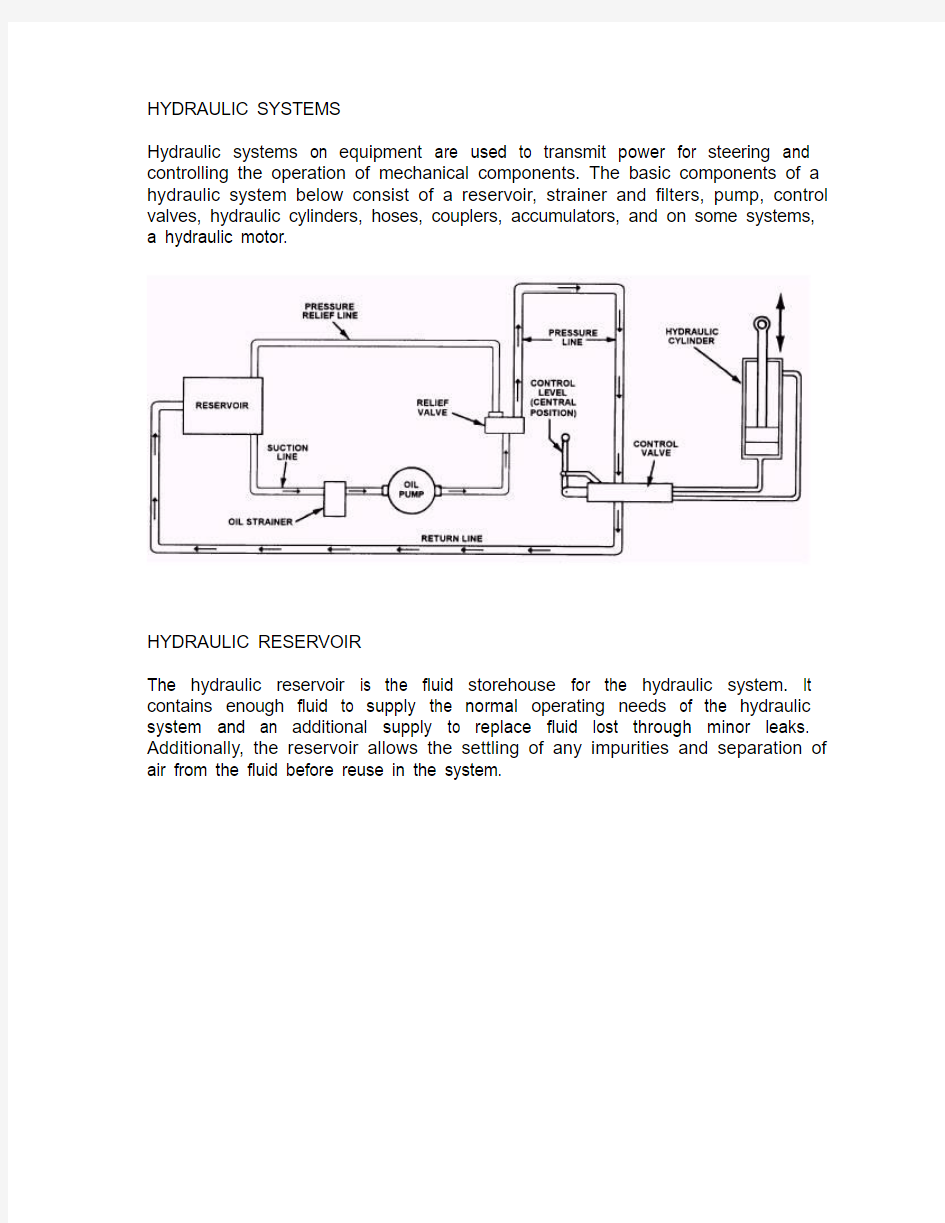
Hydraulic systems on equipment are used to transmit power for steering and controlling the operation of mechanical components. The basic components of a hydraulic system below consist of a reservoir, strainer and filters, pump, control valves, hydraulic cylinders, hoses, couplers, accumulators, and on some systems, a hydraulic motor.
HYDRAULIC RESERVOIR
The hydraulic reservoir is the fluid storehouse for the hydraulic system. It contains enough fluid to supply the normal operating needs of the hydraulic system and an additional supply to replace fluid lost through minor leaks. Additionally, the reservoir allows the settling of any impurities and separation of air from the fluid before reuse in the system.
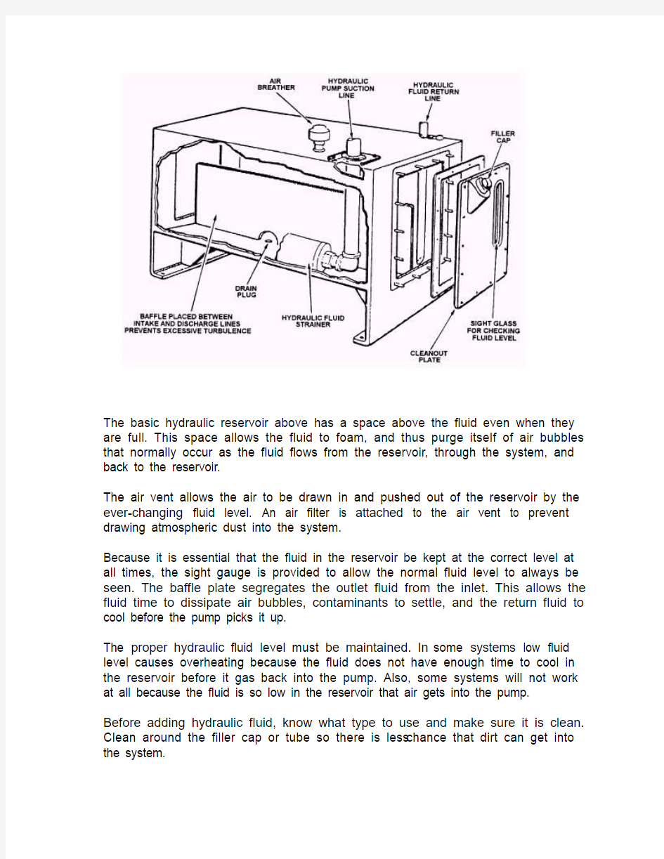
The basic hydraulic reservoir above has a space above the fluid even when they are full. This space allows the fluid to foam, and thus purge itself of air bubbles that normally occur as the fluid flows from the reservoir, through the system, and back to the reservoir.
The air vent allows the air to be drawn in and pushed out of the reservoir by the ever-changing fluid level. An air filter is attached to the air vent to prevent drawing atmospheric dust into the system.
Because it is essential that the fluid in the reservoir be kept at the correct level at all times, the sight gauge is provided to allow the normal fluid level to always be seen. The baffle plate segregates the outlet fluid from the inlet. This allows the fluid time to dissipate air bubbles, contaminants to settle, and the return fluid to cool before the pump picks it up.
The proper hydraulic fluid level must be maintained. In some systems low fluid level causes overheating because the fluid does not have enough time to cool in the reservoir before it gas back into the pump. Also, some systems will not work at all because the fluid is so low in the reservoir that air gets into the pump. Before adding hydraulic fluid, know what type to use and make sure it is clean. Clean around the filler cap or tube so there is less chance that dirt can get into the system.
STRAINERS AND FILTERS
Hydraulic systems have a strainer and one or more filters that remove the impurities that would eventually contaminate the hydraulic fluid. The strainer is normally located in the reservoir or in the inlet line to the pump. The filter is normally located so only a small amount of fluid is lost when the element is changed. The falter is equipped with a valve that allows the fluid to bypass the filter element should it become clogged. The falter element is usually of the paper cartridge, canister, or edge type and is similar to those used in engine lubrication systems. Regular filter maintenance, performed by the mechanics, is necessary to prevent contaminated fluid from being re-circulated in the system.
HYDRAULIC PUMPS & MOTORS
Vane Pump
Rotary positive-displacement pumps rely on the close contact of gears, lobes, vanes, or screws, which, when rotated, trap small pockets of fluid and transfer
them from the suction to the discharge side.
Constant Speed Variable Delivery Pump: Axial Piston Type
CONTROL VALVES
Control valves are valves accessible to the operator for directing the flow of fluid within the system to operate the machine or its attachment. By skillful use of the control valves, the operator can regulate the speed and operation of the hydraulic cylinders.
NOTE: Hydraulic controls should be operated smoothly to eliminate the jerking motion that causes rapid wear and failure of the mechanical parts of the machine. ACTUATORS
(a) a rotary vane hydraulic actuator,
(b) a linear hydraulic actuator.
The position of the control valve is changed by the input control signal, which allows oil to flow through passages to operate the actuator. As the actuator moves, its movement is transmitted along the feedback path, so cancelling out the original movement of the control valve. Thus, the output movement of the actuator is proportional to the input control movement.
ROTARY VANE ACTUATOR WITH FEEDBACK
LINEAR ACTUATOR (RAM) WITH FEEDBACK
Control valve (Spool valve)
Shut off & direction control
Double acting hydraulic cylinder
SPOOL VALVE WITH SHUT OFF & DIRECTION CONTROL
Spool valve direct fluid to various parts of the system and may be operated by hand levers, pilot pressure signals, electric solenoids, electric motors, and mechanical cams.
A typical application for a sliding spool direction valve is to control the fluid to a double-acting hydraulic cylinder which, when moving in one direction requires fluid under pressure on one side of the piston while the other side is connected to the drain line.
In the spool valve illustrated above, the three-position spool is held in its position by the feedback link.
In the central position all ports are locked. It will therefore be evident that while the valve spool remains central, the cylinder cannot be moved.
Moving the position of the spool in relation to the various ports controls the direction of flow, and if the spool is shifted to the left, High-pressure oil will flow through the valve to left side of the actuator. At the same time right side of the linear actuator will be connected to the exhaust. Thereby moving the linear actuator to the right. The spool will automatically be moved to the centre by the feedback link once the actuator has moved a certain amount proportional to the control movement.
ACCUMULATORS
Describe a hydraulic accumulator and explain its purpose.
Pressure accumulators are used in hydraulic systems where it is necessary to store pressure energy in order to meet surges in demand. They are also employed to absorb hydraulic shock loads and to compensate for small internal leakages when pressure is to be maintained with the pump stopped.
The most common form of accumulator comprises a steel shell containing a gas-filled and pressurized flexible bladder. The bladder is pre-charged to the required pressure by means of a special valve and then sealed to prevent leakage of the gas. Hydraulic fluid under pressure enters the accumulator, compressing the bladder until equilibrium is reached. When the demand for additional fluid is created by a slight fall in the system pressure, the gas expands, forcing fluid back into the system.
There is usually a large poppet valve at the fluid entry port, which automatically closes when the accumulator is exhausted, to prevent the bladder extruding into the inlet pipe. It is important that only nitrogen should be used for pre-charging as this is inert, and the gas pressure must be precisely set in accordance with the manufacturer's instructions.
FLEXIBLE HOSES
Flexible hoses are used in a hydraulic system to allow movement between mechanical parts of the equipment. Hoses are manufactured in layers as shown in figure below. The inner layer is made of synthetic materials that resist deterioration from the fluid in the system. The middle layer or layers are made of either fabric or rubber for low-pressure systems or wire braid for high pressure applications. These layers give the hose its strength.
Part of your pre- and post-operational inspections is to inspect hoses for cracking or splitting, pinhole leaks, improper hose length, rubbing, heat, twisting, and so forth. Any problems with hydraulic hoses should be repaired before use.
UICK-DISCONNECT COUPLERS
Quick-disconnect couplers below are used where hydraulic lines must be connected or disconnected frequently; for example, connecting emergency hydraulic hand pump to open a cargo tank valve, or connecting a pump to hydraulic jack.
The quick-disconnect couplers are self-sealing devices that accomplish the work of two shutoff valves and a tube coupler. They are easy to use and keep hydraulic fluid loss at a minimum. More importantly, you do not have to drain or bleed the system each time a hookup is made.
Quick-disconnect couplers consist of two halves: the body contains a spring-loaded poppet or seal, while the other half is inserted to open the poppet when the two halves are connected. A locking device holds the two halves and seals them.
When quick-disconnect couplers are disconnected on attachments, you must remember that it is very important that dust plugs are inserted in the coupler ports. If dust plugs are unavailable, a common practice is to use a plastic bag to wrap the couplers in for protection from foreign matter.
CAUTION
Hydraulic systems can create up to 200 bar pressure and the fluids may reach temperatures above 80O C in a hot system. Wear protective gloves and use extreme care when disconnecting and reconnecting quick-disconnect couplers. HYDRAULIC MOTORS
The hydraulic motor provides power to deck machinery and is used in applications where steam or electrical drives are not viable.
The hydraulic motor is turned by fluid under pressure supplied by the pump. The fluid enters the housing and acts on the rotating members. It then discharges and returns to the reservoir or pump.