CFD simulation and optimization of the ventilation for subway side-platform

CFD simulation and optimization of the ventilation for subway
side-platform
Feng-Dong Yuan *,Shi-Jun You
School of Environment Science and Technology,Tianjin University,No.72,Weijin Road,Nankai District,Tianjin 300072,China
Received 27May 2006;received in revised form 23September 2006;accepted 19October 2006
Available online 5December 2006
Abstract
To obtain the velocity and temperature ?eld of subway station and the optimized ventilation mode of subway side-platform station,this paper takes the evaluation and optimization of the ventilation for subway side-platform station as main line,builds three dimen-sional models of original and optimization design of the existed and rebuilt station.And using the two-equation turbulence model as its physics model,the thesis makes computational ?uid dynamics (CFD)simulation to subway side-platform station with the boundary conditions collected for simulation computation through ?eld measurement.It is found that the two-equation turbulence model can be used to predict velocity ?eld and temperature ?eld at the station under some reasonable presumptions in the investigation and study.At last,an optimization ventilation mode of subway side-platform station was put forward.ó2006Elsevier Ltd.All rights reserved.
Keywords:Ventilation;CFD simulation;k -e model;Subway;Side-platform
1.Introduction
Computational ?uid dynamics (CFD)software is com-monly used to simulate ?uid ?ows,particularly in complex environments (Chow and Li,1999;Zhang et al.,2006;Moureh and Flick,2003).CFD is capable of simulating a wide variety of ?uid problems (Gan and Ri?at,2004;Somarathne et al.,2005;Papakonstantinou et al.,2000;Karimipanah and Awbi,2002).CFD models can be realis-tically modeled without investing in more costly experi-mental method (Betta et al.,2004;Allocca et al.,2003;Moureh and Flick,2003).So CFD is now a popular design tool for engineers from di?erent disciplines for pursuing an optimum design due to the high cost,complexity,and lim-ited information obtained from experimental methods (Li and Chow,2003;Vardy et al.,2003;Katolidoy and Jicha,2003).Tunnel ventilation system design can be developed in depth from the predictions of various parameters,such
as vehicle emission dispersion,visibility,air velocity,etc.(Li and Chow,2003;Yau et al.,2003;Gehrke et al.,2003).Earlier CFD simulations of tunnel ventilation system mainly focus on emergency situation as ?re condition (Modic,2003;Carvel et al.,2001;Casale,2003).Many sci-entists and research workers (Waterson and Lavedrine,2003;Sigl and Rieker,2000;Gao et al.,2004;Tajadura et al.,2006)have done much work on this.This paper stud-ied the performance of CFD simulation on subway envi-ronment control system which has not been studied by other paper or research report.It is essential to calculate and simulate the di?erent designs before the construction begins,since the investment in subway’s construction is huge and the subway should run up for a few decade years.The ventilation of subway is crucial that the passengers should have fresh and high quality air (Lowndes et al.,2004;Luo and Roux,2004).Then if emergency occurred that the well-designed ventilation system can save many people’s life and belongings (Chow and Li,1999;Modic,2003;Carvel et al.,2001).The characteristics of emergency situation have been well investigated,but there have been
0886-7798/$-see front matter ó2006Elsevier Ltd.All rights reserved.doi:10.1016/j.tust.2006.10.004
*
Corresponding author.Tel.:+862287401917;fax:+862227892626.E-mail address:yuanfd@https://www.360docs.net/doc/fd5670286.html, (F.-D.Yuan).
https://www.360docs.net/doc/fd5670286.html,/locate/tust
Tunnelling and Underground Space Technology 22(2007)
474–482
Tunnelling and
Underground Space Technology
incorporating Trenchless Technology Research
few studies in air distribution of side-platform in normal conditions.
The development of large capacity and high speed com-puter and computational?uid dynamics technology makes it possible to use CFD technology to predict the air distri-bution and optimize the design project of subway ventila-tion system.Based on the human-oriented design intention in subway ventilation system,this study simu-lated and analyzed the ventilation system of existent station and original design of rebuilt stations of Tianjin subway in China with the professional software AIRPAK,and then found the optimum ventilation project for the ventilation and structure of rebuilt stations.
2.Ventilation system
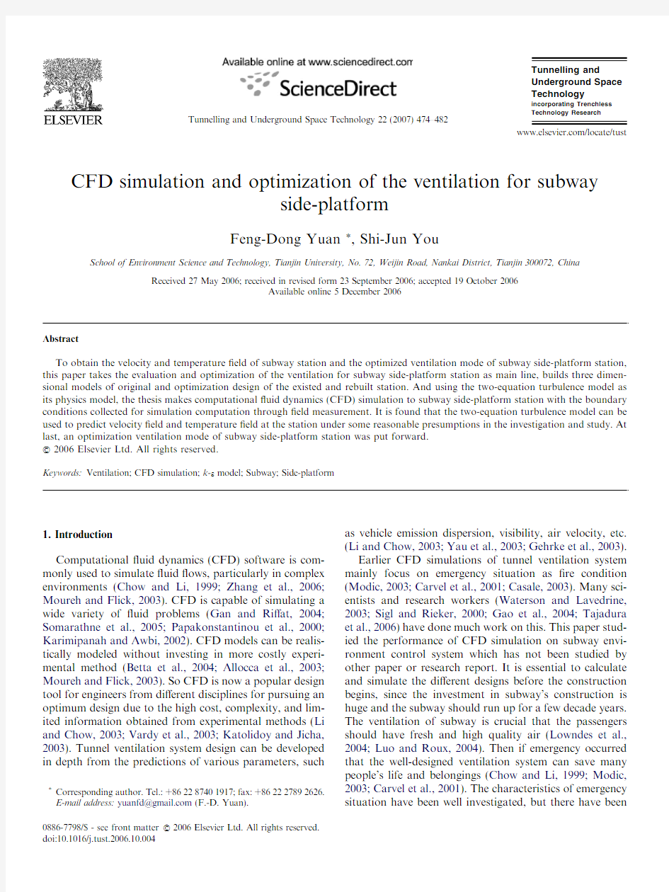
Tianjin Metro,the secondly-built subway in China,will be rebuilt to meet the demand of urban development and expected to be available for Beijing2008Olympic Games. The existent subway has eight stations,with a total length of7.335km and a0.972km average interval.For sake of saving the cost of engineering,the existent subway will con-tinue to run and the stations will be rebuilt in the rebuilding Line1of Tianjin subway.Although di?erent existent sta-tions of Tianjin Metro have di?erent structures and geom-etries,the Southwest Station is the most typical one.So the Southwest Station model was used to simulate and analyze in the study.Its geometry model is shown in Fig.1.
2.1.The structure and original ventilation mode of existent station
The subway has two run-lines.The structure of South-west Station is,length·width·height=74.4m(L)·18.7m(W)·4.4m(H),which is a typical side-platform station.Each side has only one passageway(length·height=6.4m(L)·2.9m(H)).The middle of station is the space for passengers to wait for the vehicle.The plat-form mechanical ventilation is realized with two jet open-ings located at each end of station and the supply air jets towards train and track.There is no mechanical exhaust system at the station and air is removed mechanically by tunnel fans and naturally by the exits of the station.
2.2.The design structure and ventilation of rebuilt station
The predicted passenger?ow volume increase greatly and the dimension of the original station is too small,so in the rebuilding design,the structure of subway station is changed to,(length·width·height=132m(L)·17.438m(W)·4.65m(H)),and each side has two passage-ways.The design volume?ow of Southwest Station is 400000m3/h.For most existent stations,the platform height is only2.9m,which is too low to set ceiling ducts. So in the original design,there are two grille vents at each end of the platform to supply fresh air along the platform length direction and two grille vents to jet air breadthways towards trains.The design velocity of each lengthways grille vent is5.54m/s.For each breadthways vent,it is 5.28m/s.Under the platform,80grille vents of the same velocity(4.62m/s,40for each platform of the station) are responsible for exhaust.
3.CFD simulation and optimization
The application of CFD simulation in the indoor envi-ronment is based on conversation equations of energy, mass and momentum of incompressible air.The
study Fig.1.The location of test section and the layout of measuring points.
F.-D.Yuan,S.-J.You/Tunnelling and Underground Space Technology22(2007)474–482475
adopted a turbulence energy model that is the two-equa-tion turbulence model advanced by Launder and Spalding. And it integrated the governing equation on the capital control volumes and discretized in the de?nite grids,at last simulated and computed with the AIRPAK software.
3.1.Preceding simpli?cations and presumptions
Because of mechanical ventilation and the existence of train-driven piston wind,the turbulence on platform is transient and complex.Unless some simpli?cations and presumptions are made,the mathematics model of three-dimensional?ow is not expressed and the result is diver-gent.While ensuring the reliability of the computation results,some preceding simpli?cations and presumptions have to be taken.
(1)The period of maximum air velocity is paid attention
to in the transient process.Apparently the maximum air velocity is reached at the period when train stops at or starts away from the station(Yau et al.,2003;
Gehrke et al.,2003),so the period the simulation con-cerns about the best period of time for simulation is from the point when at the section of‘x=0.0m’(Fig.1)and the air velocity begin to change under piston-e?ect to the point when train totally stops at the station(de?ned as a‘pulling-in cycle’).
(2)Though the pulling-in cycle is a transient process,it is
simpli?ed to a steady process.
(3)Because the process is presumed to a steady process,
the transient velocity of test sections,which was tested in Southwest Station in pulling-in cycle,is pre-sumed to the time-averaged velocity of test sections.
(4)The volume?ow driven into the station by pulling-in
train is determined by such factors as BR(blocking ratio,the ratio of train cross-section area to tunnel cross-section area),the length of the train and the resistance of station etc.For existent and new sta-tions,BRs are almost the same.Although the length of the latter train doubles that of the former which may increase the piston?ow volume,the resistance of latter is greater than that of the former which may counteract this increase.So it is presumed that the piston?ow volume is same for both existent and new station and that the volume?ow through the passenger exits is also same.Based on this pre-
sumption,the results of the?eld measurements at the existent station can be used as velocity boundary conditions to predict velocity?led of new station. 3.2.Original conditions
To obtain the boundary conditions for computation and simulation,such as the air velocity and temperature of enclosure,measures were done by times at Southwest Sta-tion.All data are recorded during a complete pulling-in cycle.The air velocities were measured by the multichannel anemonmaster hotwire anemoscope and infrared ther-mometer is used to measure the temperature of the walls of the station which are taken as the constant temperature thermal conditions in the simulation.
3.2.1.Temperatures of enclosure
Divide the platform into?ve segments and select some typical test positions.The distributing temperature of enclosure is shown in Table1.It can be seen from Table 1that all temperatures of enclosure are between23°C and25°C,there is little di?erence in all test positions, and the average temperature is24°C.So all temperatures of subway station’s walls is24°C in CFD computation and simulation.
3.2.2.Time-averaged air velocity above the platform
Fig.1is the location of test section and the layout of measuring points.The data measured include12transient velocities in each section(A–H in Fig.1),which were deal with section’s time-averaged velocities in the period,12 point’s velocities of passageway,which is used to acquire the average?ow,and the velocities of each end of station, which is used to acquire the average piston?ow volume.
Fig.2is the lengthways velocities measured of platform sections,V max is the maximum air velocity,V min is the minimum air velocity and V ave is the average air velocity. Fig.2shows that the maximum air velocity is at the pas-sageway.At the passageway the change of air velocity is about2.25m/s,which is the maximum and indicates that the passageway is the position e?ected most by the piston wind e?ect,and the air velocity of section D and E after the passageway is almost the same,which indicates that the piston wind can hardly e?ect the air velocity after the passageway.
Table1
Distributing temperature of enclosure
Test positions Station walls Platform
Top Railway ground Lateral wall Ground
123123123123 Temperature(°C)when x=12.8m24.824.624.823.823.823.824.223.823.623.823.823.8 Temperature(°C)when x=25.6m24.824.624.624242424.42423.623.423.824 Temperature(°C)when x=38.4m24.82524.824242424.423.823.623.623.223.6 Temperature(°C)when x=51.2m24.424.424.424.224.224.224.224.223.42323.423.4 476 F.-D.Yuan,S.-J.You/Tunnelling and Underground Space Technology22(2007)474–482
In addition,because of the movement of train,the veloc-ity cannot be measured in section U of Fig.1,the air veloc-ity of section U was computed in CFD simulation.
3.2.3.Boundary conditions of simulation
Through analyzing the boundary data measured at the Southwest Station,the boundary conditions of the existent station in CFD simulation is shown in Table2.Addition-ally,the Tianjin Metro is out of run during the measuring time,so the heat load is not typical and is di?cult to be determined so that the distributing temperature was not simulated in this study.
Referred to the feasibility research report of No.3 design institute of China’s ministry of railway and the mea-sured data in Southwest Station,the boundary conditions of new station in CFD simulation of the existent station is shown in Table3.
3.3.Solution process
3.3.1.Method of solution
The governing equations to calculate original variables, such as velocity and temperature etc.,can be shown (Moureh and Flick,2003).
o
o t
eq/Ttdiveq~u/T?diveC grad/TtSe1Twhere/is common variable and denotes(u,v,w,T),~u is velocity vector,q is density,C is dissipation function,S is the source item.u is air velocity of direction X,v and w are air velocities of direction Y and Z,respectively,and T is air temperature.
Eq.(1)is integrated on the spatial control volumes,and through discretizing in the de?nite
grids Fig.2.Measured lengthways velocities at platform sections.
Table2
Boundary condition of existent stations in CFD simulation
Sections Section G Section U
(estimated)Section H Passageway of the train-
stopping side:EXIT1
Passageway of the non-train
stopping side:EXIT2
The exit of
train F
Air velocity(m/s)0.670.670.670.670.670.67 Air?ow(m3/s)0.670.670.670.670.670.67 Table3
Boundary condition of rebuilt stations in CFD simulation
(a)Heat load
Persons Lamps(on the top
of platform)Advertisement lamps(lateral
wall of platform)
Heat emitted from train
Heat
load 44kW/
person
13W/m215kW/station320kW(acceleration)and200kW
(heat from applying brake)
(b)Air velocity
Supply air(lengthways)Supply air(breadthways)Under the platform vents Air velocity(m/s) 5.54 5.28 4.62
(c)Boundary conditions of air velocity
The entrance of train The exit of
train
Passageway of the train-stopping
side
Passageway of the non-train-stopping
side
Boundary conditions
of air velocity(m/s)
0.2–0.590.41 1.440.97
(d)Temperature
Train walls(expert for excluding top and bottom of train)Outdoor air
(summer)
Supply air
(summer)
Tunnel
air
Enclosure
walls
Temperature (°C)2727272524
F.-D.Yuan,S.-J.You/Tunnelling and Underground Space Technology22(2007)474–482477
a p/?
X
nb a nb/
nb
tbe2T
In Eq.(2),nb denotes neighbor grids;a p and a nb are the coe?cients of/and/nb,respectively,b is the source item.
(2)Tables4and5shows solution,cycle type and convergence criterion and relaxation coe?cient in CFD simulation of the existent station ventilation and the new station.
3.4.Simulation and discussion
Used the boundary conditions measured in Southwest Station,the air velocity of subway side-platform station was simulated in AIRPAK.Fig.3is the air velocity com-parison of simulation and measurement in section A–E, which shows that the two-equation model and the preced-ing simpli?cations are acceptable in predicting?ow at the station.Although the computed velocity at section C and E is not equal to the values of the?eld measurement,whose error is about0.1–0.2m/s,the di?erences are acceptable and the overall variance trend of the velocity along the platform tallies with the measurement.The simulation result of air velocity of1.7m height above platform of exis-tent station can be seen in Fig.4.Fig.4shows that the majority of piston winds pour out from the passageway and the air velocity of the zone after the passageway is lower,which is below0.4m/s.The maximum air velocity at1.7m height above platform is the passageway of the train-stopping side,which is about1.89m/s.
The simulation results indicate that it is applicable to use two-equation turbulence model to predict time-averaged ?ow and temperature distribution at subway station so the veracity is reliable.
Fig.5is the simulation result,which is the original design of air velocity at1.7m height above platform of new station.It is shown from Fig.5that at the train-ing-stopping side of platform the supply air does not reach the zone between the two exits,which is for the passenger to wait for the train,and pour out from the passageway because of the leakage of passageway.The air velocity between two passageways,which is below 0.4m/s,is a little low so that the‘Dead Zone’is formed. The simulation also shows that the maximum velocity exists at the exits,which agrees with the references and experience.
Fig.6is the temperature distribution at1.7m height above platform of the new station,which is used to simu-late for original design ventilation mode.It shows that the temperature distribution is imbalanced for the leakage of exits at the training-stop side of platform,and at each end of platform,the temperature should be approximately between24°C and26°C while the temperature is between 32°C and34°C because the heat away from the train can not be cooled and removed by the cold supply air in time, even at the x=61m point,the temperature reaches above 40°C,which makes people feel uncomfortable.
The simulation result of temperature and air velocity of original design at the lengthways center section is shown in
Table4
Settlement of existent station ventilation CFD simulation
Variable Pressure Kinetic k e
Discretization Body force weighted Second order upwind Second order upwind Second order upwind Relaxation coe?cient0.3–1.00.3–1.00.3–1.00.3–1.0
Solution Pressure AMG a Kinetic AMG k AMG e AMG
Cycle type V-type Flexible Flexible Flexible
a AMG is algebra multi-grid.
Table5
Settlement of new station ventilation CFD simulation
Variable Pressure Temperature Kinetic k e
Discretization Body force weighted Second order upwind First order upwind First order upwind First order upwind Relaxation coe?cient0.3–1.00.3–1.00.3–1.00.3–1.00.3–1.0
Solution Pressure AMG Temperature AMG Kinetic AMG k AMG e AMG
Cycle type V-type Flexible Flexible Flexible
Flexible Fig.3.Air velocity of section A–E simulation and measurement.
478 F.-D.Yuan,S.-J.You/Tunnelling and Underground Space Technology22(2007)474–482
Fig.7,which shows that the distribution of temperature and air velocity is not balanceable and the zone between two exits is ‘Dead Zone’.
From the simulation of original design,the following can be seen:(1)The ventilation mode that the feasibility research
report design for the side-platform station of subway makes the distribution of temperature and air veloc-ity unbalanced,so the passengers will feel uncomfort-able at the middle of
platform.
Fig.4.Simulation result of air velocity at 1.7m height above platform of existent
station.
Fig.5.Simulation result of air velocity at 1.7m height above platform of new station (original
design).
Fig.6.Simulation result of temperature at 1.7m height above platform of new station (original design).
F.-D.Yuan,S.-J.You /Tunnelling and Underground Space Technology 22(2007)474–482479
(2)The air velocity is too high at some position of plat-
form and the passengers feel easily the change of air velocity,whose scope is between0.4m/s and2.5m/s, and feel uncomfortable when they go to exits from the middle of platform.
(3)The e?ciency of ventilation is not as good as expec-
tation and the supply air from jet fans cannot reach the middle of platform adequately and part of them will?ow away from the passageways.
Because of the unbalanced distribution of temperature and air velocity,original design’s ventilation mode was optimized.The exhaust vents are as same as that of original ones.The?ow of supplied air remains the same and under the platform there are tubes of supplied fresh air.Also there are some vertical tubes fetched out by platform.As a result,the air is supplied widthways and reasonably the ?ow of supplied air is delivered in balance,which elimi-nates the unbalanced distribution of temperature and air velocity on the platform.On the other hand the breadth-ways supplied air prevents the heat brought by train from di?using onto the platform,and the heat can be vented in time from the exhaust vents under the platform.At the same time the fresh air from the breadthways vents passes through the passengers,takes away heat and humidity,and the e?ciency of ventilation is quite satisfactory.
To validate the optimization ventilation mode,the sim-ulation adopted the same boundary conditions and set up with original design’s CFD simulation.The simulation results are showed in Figs.8and9.
Fig.8is the air velocity distribution at1.7m height above platform of new station,which is simulated for optimization design ventilation mode.It shows that the distribution of air velocity is good enough and balanced. The breadthways supplied air makes the‘Dead Zone’disappeared,and the maximum air velocity is only about 1.67m/s at 1.7m height above platform of new station,which makes it di?cult for passengers to feel windy.
Fig.9is the simulation result of temperature and air velocity of original design at the lengthways center section, which shows that the‘Dead Zone’disappears at the length-ways center section.And the breadthways supplied air pre-vents the heat,which is from the air conditioning condenser and the friction produced by train-stopping, from di?using to the platform,so the temperature is about below28°C.
Compared with the ventilation mode in original design, the optimization ventilation mode has several advantages as follows:
(1)The supply air is delivered to every zone in a balanced
way and the distribution of temperature and air velocity of side-platform is also balanced.
(2)The air velocity is balanced and the maximum is only
about1.67
m/s.
Fig.7.Simulation result of temperature and air velocity at the lengthways center section(original
design).
Fig.8.Simulation result of air velocity at1.7m height above platform of new station(optimization design). 480 F.-D.Yuan,S.-J.You/Tunnelling and Underground Space Technology22(2007)474–482
(3)The supplied air removes the heat of platform better
and the whole platform’s temperature is lower than that of the original design,which can lower tempera-ture standard and can decrease the ?ow of supply air to save energy.
(4)The supplied air from breadthways vents also well
prevents the hot contaminated train-driven air from spreading onto the platform,and on the other hand the fresh air from the breadthways vents passes through the passengers,takes away heat and humid-ity,collects and is exhausted by the under-platform vents.
(5)The ventilation e?ciency is quite satisfactory.
4.Conclusions
The following can be concluded from this study:
The air ?ow in platform of subway is a complex three-dimensional transient turbulence.Simpli?cation of the air ?ow to steady process and presumption of the transient velocity to the time-averaged velocity are applicable to sim-ulate the distribution of temperature and air velocity of subway platform in the pulling-in cycle.
It is applicable to use two-equation turbulence model to predict time-averaged velocity and temperature distribu-tion at subway station.The simulation results are in?u-enced greatly by the boundary conditions such as boundary velocity and temperature.
The optimization ventilation mode has more advantages than the original design’s.The breadthways ventilation is suggested when the height of platform is too low to have ceiling ducts.It makes the distribution of temperature and air velocity balanced.
Before a design is accepted it is very necessary to evalu-ate and optimize it by such techniques as CFD,etc.It will help a lot to build a reliable,e?ective and economical system.
Acknowledgement
This project was supported by the funding generated by the Tianjin Municipal Science and Technology Commis-sion of China (Project No:033112911).
References
Allocca,C.,Chen,Q.Y.,Glicksman,L.R.,2003.Design analysis of single-sided natural ventilation.Energy and Buildings 35,785–795.
Betta,V.,Cascetta,F.,Labruna,P.,Palombo,A.,2004.A numerical
approach for air velocity predictions in front of exhaust ?ange slot openings.Building and Environment 39,9–18.
Carvel,R.O.,Beard,A.N.,Jowitt,P.W.,2001.The in?uence of longitu-dinal ventilation systems on ?res in tunnels.Tunnelling and Under-ground Space Technology 16,3–21.
Casale,E.,2003.The automation of the aeraulic response in the case of a
?re in a tunnel-?rst concrete answers.In:Proceedings of Claiming the Underground Space,pp.185–191.
Chow,W.K.,Li,J.S.M.,1999.Safety requirement and regulations reviews
on ventilation and ?re for tunnels in the Hong Kong Special Administration Region.Tunnelling and Underground Space Technol-ogy 14,13–21.
Gan,G.H.,Ri?at,S.B.,2004.CFD modelling of air ?ow and thermal
performance of an atrium integrated with photovoltaics.Building and Environment 39,735–748.
Gao,P.Z.,Liu,S.L.,Chow,W.K.,Fong,N.K.,https://www.360docs.net/doc/fd5670286.html,rge eddy
simulations for studying tunnel smoke ventilation.Tunnelling and Underground Space Technology 19,577–586.
Gehrke,P.J.,Stacev,C.H.B.,Agnew,N.D.,2003.Rail tunnel temperature
strati?cation and implications for train and tunnel ventilation design.In:Proceedings of 11th International Symposium on Aerodynamics and Ventilation of Vehicle Tunnels,pp.727–741.
Karimipanah,T.,Awbi,H.B.,2002.Theoretical and experimental
investigation of impinging jet ventilation and comparison with wall displacement ventilation.Building and Environment 37,1329–1342.
Katolidoy,J.,Jicha,M.,2003.Eulerian-Lagrangian model for tra?c
dynamics and its impact on operational ventilation of road tunnel.In:Proceedings of 11th International Symposium on Aerodynamics and Ventilation of Vehicle Tunnels,pp.877–891.
Li,J.S.M.,Chow,W.K.,2003.Numerical studies on performance
evaluation of tunnel ventilation safety systems.Tunnelling and Underground Space Technology 18,435–452.
Lowndes,Ian S.,Crossley,Amanda J.,Yang,Zhi Yuan,2004.The
ventilation and climate modeling of rapid development tunnel drivages.Tunnelling and Underground Space Technology 19,139–150.Luo,S.,Roux,B.,2004.Modeling of the HESCO nozzle di?user used in
IEA Annex-20experiment test room.Building and Environment 39,367–384.
Modic,J.,2003.Fire simulation in road tunnels.Tunnelling and
Underground Space Technology 18,525–530.
Moureh,J.,Flick, D.,2003.Wall air-jet characteristics and air?ow
patterns within a slot ventilated enclosure.International Journal of Thermal Sciences 42,703–711.
Papakonstantinou,K.A.,Kiranoudis, C.T.,Markatos,N.C.,2000.
Computational analysis of thermal comfort:the case of the archae-ological museum of Athens.Applied Mathematical Modelling 24,477–
494.
Fig.9.Simulation result of temperature and air velocity at the lengthways center section (optimization design).
F.-D.Yuan,S.-J.You /Tunnelling and Underground Space Technology 22(2007)474–482481
Sigl,O.,Rieker,K.,2000.NATM tunnelling in Singapore old alluvium-design assumptions and construction experience.In:International Conference on Tunnels and Underground Structures.pp.205–212. Somarathne,S.,Seymour,M.,Kolokotroni,M.,2005.Dynamic thermal CFD simulation of a typical o?ce by e?cient transient solution methods.Building and Environment40,887–896.
Tajadura,R.B.,Carlos,S.M.,Eduardo,B.M.,2006.In?uence of the slope in the ventilation semi-transversal system of an urban tunnel.
Tunnelling and Underground Space Technology21,21–28.
Vardy,A.E.,Mori,E.,Yokota,M.,Nakahori,I.,2003.Model-based predictive control of road tunnel portal emissions.In:Proceedings of Claiming the Underground Space,pp.207–212.Waterson,N.P.,Lavedrine,J.,2003.Evaluation of a simpli?ed model for the design of ventilation systems in tunnel networks.In:Proceedings of 11th International Symposium on Aerodynamics and Ventilation of Vehicle Tunnels,pp.219–229.
Yau,R.,Cheng,V.,Lau,K.P.,Lai,F.,2003.Design and analysis of tunnel ventilation system for the extension of an existing railway tunnel in Hong Kong.In:Proceedings of11th International Sympo-sium on Aerodynamics and Ventilation of Vehicle Tunnels,pp.323–338.
Zhang,Lin,Feng,Jiang,Chow,T.T.,Tsang,C.F.,Lu,W.Z.,2006.CFD analysis of ventilation e?ectiveness in a public transport interchange.
Building and Environment41,254–261.
482 F.-D.Yuan,S.-J.You/Tunnelling and Underground Space Technology22(2007)474–482
第七 章 CFD仿真模拟
第七章CFD仿真模拟 一.初识CFD CFD是英文Computational Fluid Dynamics(计算流体动力学)的简称。它是伴随着计算机技术、数值计算技术的发展而发展的。简单地说,CFD相当于"虚拟"地在计算机做实验,用以模拟仿真实际的流体流动情况。而其基本原理则是数值求解控制流体流动的微分方程,得出流体流动的流场在连续区域上的离散分布,从而近似模拟流体流动情况。可以认为CFD是现代模拟仿真技术的一种。 1933年,英国人Thom首次用手摇计算机数值求解了二维粘性流体偏微分方程,CFD由此而生。1974年,丹麦的Nielsen首次将CFD用于暖通空调工程领域,对通风房间内的空气流动进行模拟。之后短短的20多年内,CFD技术在暖通空调工程中的研究和应用进行得如火如荼。如今,CFD技术逐渐成为广大空调工程师和建筑师解决分析工程问题的有力工具。 二.为什么用CFD CFD是一种模拟仿真技术,在暖通空调工程中的应用主要在于模拟预测室内外或设备内的空气或其他工质流体的流动情况。以预测室内空气分布为例,目前在暖通空调工程中采用的方法主要有四种:射流公式,Zonal model,CFD以及模型实验。 由于建筑空间越来越向复杂化、多样化和大型化发展,实际空调通风房间的气流组织形式变化多样,而传统的射流理论分析方法采用的是基于某些标准或理想条件理论分析或试验得到的射流公式对空调送风口射流的轴心速度和温度、射流轨迹等进行预测,势必会带来较大的误差。并且,射流分析方法只能给出室内的一些集总参数性的信息,不能给出设计人员所需的详细资料,无法满足设计者详细了解室内空气分布情况的要求; Zonal model是将房间划分为一些有限的宏观区域,认为区域内的相关参数如温度、浓度相等,而区域间存在热质交换,通过建立质量和能量守恒方程并充分考虑了区域间压差和流动的关系来研究房间内的温度分布以及流动情况,因此模拟得到的实际上还只是一种相对"精确"的集总结果,且在机械通风中的应用还存在较多问题; 模型实验虽然能够得到设计人员所需要的各种数据,但需要较长的实验周期和昂贵的实验费用,搭建实验模型耗资很大,有文献指出单个实验通常耗资3000~20000美元,而对于不同的条件,可能还需要多个实验,耗资更多,周期也长达数月以上,难于在工程设计中广泛采用。 另一方面,CFD具有成本低、速度快、资料完备且可模拟各种不同的工况等独特的优点,故其逐渐受到人们的青睐。由表1给出的四种室内空气分布预测方法的对比可见,就目前的三种理论预测室内空气分布的方法而言,CFD方法确实具有不可比拟的优点,且由于当前计算机技术的发展,CFD方法的计算周期和成本完全可以为工程应用所接受。尽管CFD方法还存在可靠性和对实际问题的可算性等问题,但这些问题已经逐步得到发展和解决。因此,CFD方法可应用于对室内空气分布情况进行模拟和预测,从而得到房间内速度、温度、湿度以及有害物浓度等物理量的详细分布情况。 进一步而言,对于室外空气流动以及其它设备内的流体流动的模拟预测,一般只有模型实验或CFD方法适用。表1的比较同样表明了CFD方法比模型实验的优越性。故此,CFD方法可作为解决暖通空调工程的流动和传热传质问题的强有力工具而推广应用。 表1四种暖通空调房间空气分布的预测方法比较 比较项目 1射流公式 2 ZONAL MODEL 3CFD 4模型实验 房间形状复杂程度简单较复杂基本不限基本不限 ?对经验参数的依赖性几乎完全很依赖一些不依赖
医药工业洁净厂房设计要求规范
医药工业洁净厂房设计规范 第一章总则 第1.0.1条为了贯彻执行国家《药品生产质量管理规范》(以下简称GMP),提出符合GMP要求的生产厂房、设施及设备的设计要求,特制订本规范。 第1.0.2条本规范适用于新建、改建和扩建的医药制剂、原料药和药用辅料的精制、干燥、包装工序,直接接触药品的药用包装材料、无菌医疗器械等医药工业洁净厂房的设计。 第1.0.3条医药工业洁净厂房诉设计必须贯彻国家有关方针、政策。做到技术先进、确保质量、安全实用、经济合理,符合节约能源和保护环境的要求。 第1.0.4条医药工业洁净厂房的设计,既要满足当前产品生产的工艺要求,也应适当考虑今后生产发展和工艺改进的需要。 第1.0.5条在利用原有建筑和设施进行洁净技术改造时,可根据生产工艺要求,从实际出发,充分利用现有的技术设施,符合因地制宜的原则。 第1.0.6条医药工业洁净厂房的设计应为施工安装、维护、管理、检修、测试和安全运行创造必要的条件。 第1.0.7条医药工业洁净厂房的设计除应执行本规范外,还应符合现行的国家标准、规范和规定的有关要求。 第二章生产区域的环境参数 第一节一般规定 第2.1.1条为了保证医药产品生产质量,防止生产环境对产品的污染,生产区域必须满足规定的环境参数标准。
注2:空气洁净度的测试以静态条件为依据,测试方法应符合国家医药管理工业洁净室和洁净区悬浮粒子的测试方法》中有关规定; 注3:对于空气洁净度为100级的洁净室,室内大于等于5μm尘粒的计数,应进行多次采样,当其多次出现时,方可认为该测试数值是可靠的。 第2.2.2条药品生产有关工序和环境区域的空气洁净度等级按国家CMP等有关规定确定。 第2.2.3条洁净室内的温度和湿度应符合下列规定: 一、生产工艺对温度和湿度无特殊要求时,以穿着洁净工作服不产生不舒服感为宜。空气洁净度100级、10000级区域一般控制温度为20~24℃,相对湿度为45~60%。100000级区域一般控制温度为18~28℃,相对湿度为50~65%。 二、生产工艺对温度和湿度有特殊要求时,应根据工艺要求确定。 第2.2.4条洁净室内应保持一定的新鲜空气量,其数值应取下列风量中的最大值: 一、非单向流洁净室总送风量的10~30%,单向流洁净室总送风量的2~4%; 二、补偿室内排风和保持室内正压值所需的新鲜空气量; 三、保证室内每人每小时的新鲜空气量不小于40m3。 第2.2.5条洁净室必须维持一定的正压。不同空气洁净度的洁净区之间以及洁净区与非洁净区之间的静压差不应小于5Pa,洁净区与室外的静压差不应小于10Pa。 青霉素等特殊药物生产洁净区,固体口服制剂配料、制粒、压片等工序洁净区的气压控制,应符合第8.5.1条要求。 第2.2.6条洁净室和洁净区应根据生产要求提供足够的照度。主要工作室一般照明的照度值不宜低于300LX;辅助工作室、走廊、气闸室、人员净化和物料净化用室可低于300LX,但不宜低于150LX。对照度要求高的部位可增加局部照明。
一维CFD模拟仿真设计
CFD simulation in Laval nozzle SIAE 090441313 Abstract We aim to simulate the quasi one dimension flow in the Laval nozzle based on CFD computation in this paper .We consider the change of the temperature ,the pressure ,the density and the speed of the flow to study the flow.The analytic solution of the flow in the Laval nozzle is provided when the input velocity is supersonic.We use the Mac-Cormack Explicit Difference Scheme to slove the question. Key words :Laval nozzle ,CFD,throat narrow. Contents Abstract .................................................. . (1) Introduction .............................................. .. (2) Simulation of one-dimensional steady flow (3)
Basis equations ................................................. (3) Dimensionless .......................................... . (10) Mac -Cormack Explicit Difference Scheme (11) Boundary conditions ................................................ (13) Reference .............................................. (13) Annex .................................................. .. (14) Introduction Laval nozzle is the most commonly used components of rocket engines and aero-engine, constituted by two tapered tube, one shrink tube, another expansion tube. Laval nozzle is an important part of the thrust chamber. The first half of the nozzle from large to small contraction to a narrow throat to the middle. Narrow throat and then expand
洁净厂房设计规范2019
1 总则 1.0.1为在医药工业洁浄厂房设计中贯彻执行国家有关方针政策,做到技术先进、安全可靠、确保质量、节能环保,制定本标准 1.0.2本标准适用于新建、扩建和改建的医药工业洁净厂房设计。生物制品、毒性药品、精神药品、麻醉药品以及放射性药品的生产和质量检验设施除应执行本标准外,尚应符合国家有关的监管规定。 1.0.3医药工业洁净厂房的设计应为施工安装、系统设施验证、维护管理、检修测试和安全运行创造必要的条件 1.0.4医药工业洁净厂房的设计除应符合本标准外,尚应符合国家现行有关标准规范的规定。 2术语 2.0.1医药洁净室pharmaceutical clean room 空气悬浮粒子和微生物浓度,以及温度、湿度、压力等参数受控的医药生产房间或限定的空间。
2.0.2医药工业洁净厂房pharmaceutical industry clean room 包含医药洁净室的用于药品生产及质量控制的建筑物 2.0.3人员净化用室room forcleaning personne 人员在进人医药洁净室之前按一定程序进行净化的房间 2.0.4物料净化用室room forcleaning materia 物料在进入医药洁净室之前按一定程序进行净化的房间 2.0.5受控环境controlled environment 以规定方法对污染源进行控制的特定区域 2.0.6悬浮粒子airborne particles 用于空气洁净度分级的空气悬浮粒子尺寸范围在0.1um~1000um 的固体和液体粒子。 2.0.7微生物microorganIsms 能够复制或传递基因物质的细菌或非细菌的微小生物实体 2.0.8含尘浓度particle concentration 单位体积空气中悬浮粒子的数量
CFD仿真验证及有效性指南
CFD仿真验证及有效性指南 摘要 本文提出评估CFD建模和仿真可信性的指导方法。评估可信度的两个主要原则是:验证和有效。验证,即确定计算模拟是否准确表现概念模型的过程,但不要求仿真和现实世界相关联。有效,即确定计算模拟是否表现真实世界的过程。本文定义一些重要术语,讨论基本概念,并指定进行CFD仿真验证和有效的一般程序。本文目的在于提供验证和有效的重要问题和概念的基础,因为一些尚未解决的重要问题,本文不建议作为该领域的标准。希望该指南通过建立验证和有效的共同术语和方法,以助于CFD仿真的研究、发展和使用。这些术语和方法也可用于其他工程和科学学科。 前言 现在,使用计算机模拟流体的流动过程,用于设计,研究和工程系统的运行,并确定这些系统在不同工况下的性能。CFD模拟也用于提高对流体物理和化学性质的理解,如湍流和燃烧,有助于天气预报和海洋。虽然CFD模拟广泛用于工业、政府和学术界,但目前评估其可信度的方法还很少。这些指导原则基于以下概念,没有适用于所有CFD模拟的固定的可信度和精确度。模拟所需的精确度取决于模拟的目的。 建立可信度的两个主要原则是验证和有效(V&V)。这里定义,验证即确定模型能准确表现设计者概念模型的描述和模型解决方案的过程,有效即确定预期模型对现实世界表现的准确度的过程。该定义表明,V&V的定义还在变动,还没有一个明确的最终定义。通常完成或充分由实际问题决定,如预算限制和模型的预期用途。复合建模和计算模拟没有任何包括准确性的证明,如在数学分析方面的发展。V&V的定义也强调准确度的评价,一般在验证过程中,准确度以对简化模型问题的基准解决方法符合性确定;有效性时,准确度以对实验数据即现实的符合性确定。 通常,不确定性和误差可视为与建模和仿真准确度相关的正常损失。不确定性,即在任一建模过程中由于缺乏知识导致的潜在缺陷。知识缺乏通常是由对物理特性或参数的不完全了解造成的,如对涡轮叶片表面粗糙度分布的不充分描述。知识缺乏的另一个原因是物理过程的复杂性,如湍流燃烧。误差即在建模和
车流量仿真分析-Flotran CFD
2006年用户年会论文 基于ANSYS流体动力学的车流量仿真分析1 [刘长虹,郑杰,朱晓华,张海波,黄虎,陈力华] [上海工程技术大学汽车工程学院,上海,201600] [ 摘要 ] 将交通流比拟为管道流体模型并且利用有限元分析软件ANSYS中的FLOTRAN CFD流体分析模块对隧道口交通流进行比拟及仿真,得出相应交通流量模型和车辆流动模拟图。并对不同车速下 交叉道口的通行能力进行模拟,确定出最佳车速比。且对不同入口形状进行车流通畅度的 ANSYA软件比较模拟,通过模拟直观的展示出不同道路入口形状对车流和道路的影响。最后对 高峰路段路口设计提出有关建议。 [ 关键词]交通流,交通流模型,ANSYS,模拟 Simulating to Traffic Flux By the ANSYS Fluid Dynamic Analysis [Liu Changhong, Zheng Jie, Zhu Xiaohua, Zhang Haibo, Huang Hu, Chen Lihua] [Automobile College Shanghai University of Engineering Science, Shanghai 201600] [Abstract ] Firstly, based on the fluid dynamic mechanics of channel, a traffic flow model is built. Secondly, the traffic flow model on cross road is simulated with the finite element method software (ANSYS). Then according to the calculating results, the simulating traffic ability at the entrance of the roadl in different speed and the different entrance figures are calculated directly. Finally, some suggestions of designing the heavy road are given. [ Keyword ] traffic flow, traffic flow simulation, ANSYS, Simulation. 1.前言 当前,社会经济的迅速发展与交通建设的相对滞后,已经构成非常突出的世界性矛盾,在发展中国家尤其突出。在我国许多大城市中,交通堵塞,事故频繁,成了众所周知的“都市顽症”。以上海市为例,上世纪九十年代的资料表明,在交通高峰期,市中心机动车平均车速不到15km/h,最低的车速仅仅为4km/h,即低于正常的步行速度。解决这个矛盾的一个重要办法是大力进行市政交通建设,实现交通的立体化,现代化。同时还要保证建设道路的合理性。交通流理论是解决这类方法的一种理论方法[1,2],其中有根据流体动力学理 1上海市教委基金项目(041NE31)和上海市科委基金项目(04QMX1452)资助
医药工业洁净厂房设计规范
医药工业洁净厂房设计规 范 Jenny was compiled in January 2021
医药工业洁净厂房设计规范 第一章总则 第条为了贯彻执行国家《药品生产质量管理规范》(以下简称GMP),提出符合GMP要求的生产厂房、设施及设备的设计要求,特制订本规范。 第条本规范适用于新建、改建和扩建的医药制剂、原料药和药用辅料的精制、干燥、包装工序,直接接触药品的药用包装材料、无菌医疗器械等医药工业洁净厂房的设计。 第条医药工业洁净厂房诉设计必须贯彻国家有关方针、政策。做到技术先进、确保质量、安全实用、经济合理,符合节约能源和保护环境的要求。 第条医药工业洁净厂房的设计,既要满足当前产品生产的工艺要求,也应适当考虑今后生产发展和工艺改进的需要。 第条在利用原有建筑和设施进行洁净技术改造时,可根据生产工艺要求,从实际出发,充分利用现有的技术设施,符合因地制宜的原则。 第条医药工业洁净厂房的设计应为施工安装、维护、管理、检修、测试和安全运行创造必要的条件。 第条医药工业洁净厂房的设计除应执行本规范外,还应符合现行的国家标准、规范和规定的有关要求。 第二章生产区域的环境参数 第一节一般规定 第条为了保证医药产品生产质量,防止生产环境对产品的污染,生产区
注3:对于空气洁净度为100级的洁净室,室内大于等于5μm尘粒的计数,应进行多次采样,当其多次出现时,方可认为该测试数值是可靠的。 第2.2.2条药品生产有关工序和环境区域的空气洁净度等级按国家CMP等有关规定确定。 第2.2.3条洁净室内的温度和湿度应符合下列规定: 一、生产工艺对温度和湿度无特殊要求时,以穿着洁净工作服不产生不舒服感为宜。空气洁净度100级、10000级区域一般控制温度为20~24℃,相对湿度为45~60%。100000级区域一般控制温度为18~28℃,相对湿度为50~65%。 二、生产工艺对温度和湿度有特殊要求时,应根据工艺要求确定。 第2.2.4条洁净室内应保持一定的新鲜空气量,其数值应取下列风量中的最大值: 一、非单向流洁净室总送风量的10~30%,单向流洁净室总送风量的2~4%; 二、补偿室内排风和保持室内正压值所需的新鲜空气量; 三、保证室内每人每小时的新鲜空气量不小于40m3。 第2.2.5条洁净室必须维持一定的正压。不同空气洁净度的洁净区之间以及洁净区与非洁净区之间的静压差不应小于5Pa,洁净区与室外的静压差不应小于10Pa。 青霉素等特殊药物生产洁净区,固体口服制剂配料、制粒、压片等工序洁净区的气压控制,应符合第条要求。
医药工业洁净厂房设计规范GMP-97
医药工业洁净厂房设计规范 GMP—97 目录 医药工业洁净厂房设计规范 (1) 第一章总则 (2) 第二章生产区域的环境参数 (2) 第一节一般规定 (2) 第二节环境参数的设计要求 (2) 第三章厂址选择和总平面布置 (3) 第一节厂址选择 (3) 第二节总平面布置 (4) 第四章工艺设计 (4) 第一节工艺布局 (4) 第二节人员净化 (5) 第三节物料净化 (6) 第五章设备 (6) 第六章工艺管道 (8) 第一节一般规定 (8) 第二节管道材料、阀门和附件 (8) 第三节管道的安装、保温 (8) 第四节安全 (9) 第七章建筑 (9) 第一节一般规定 (9) 第二节防火和疏散 (9) 第三节室内装修 (10) 第八章空气净化 (11) 第一节一般规定 (11) 第二节净化空气调节系统 (11) 第三节气流组织 (12) 第四节风管和附件 (13) 第五节青霉素等药物生产洁净室的特殊要求 (13) 第九章给水排水 (14) 第一节一般规定 (14) 第二节给水 (14) 第三节排水 (14) 第四节工艺用水 (14) 第五节消防设施 (15) 第十章电气 (16) 第一节配电 (16) 第二节照明 (16) 第三节其它电气 (17) 附录一名词解释 (18) 附录二本规范用词说明 (19)
第一章总则 第1.0.1条为了贯彻执行国家《药品生产质量管理规范》(以下简称GMP),提出符合GMP要求的生产厂房、设施及设备的设计要求,特制订本规范。 第1.0.2条本规范适用于新建、改建和扩建的医药制剂、原料药和药用辅料的精制、干燥、包装工序,直接接触药品的药用包装材料、无菌医疗器械等医药工业洁净厂房的设计。 第1.0.3条医药工业洁净厂房诉设计必须贯彻国家有关方针、政策。做到技术先进、确保质量、安全实用、经济合理,符合节约能源和保护环境的要求。 第1.0.4条医药工业洁净厂房的设计,既要满足当前产品生产的工艺要求,也应适当考虑今后生产发展和工艺改进的需要。 第1.0.5条在利用原有建筑和设施进行洁净技术改造时,可根据生产工艺要求,从实际出发,充分利用现有的技术设施,符合因地制宜的原则。 第1.0.6条医药工业洁净厂房的设计应为施工安装、维护、管理、检修、测试和安全运行创造必要的条件。 第1.0.7条医药工业洁净厂房的设计除应执行本规范外,还应符合现行的国家标准、规范和规定的有关要求。 第二章生产区域的环境参数 第一节一般规定 第2.1.1条为了保证医药产品生产质量,防止生产环境对产品的污染,生产区域必须满足规定的环境参数标准。 第2.1.2条医药工业洁净室和洁净区应以微粒和微生物为主要控制对象,同时还应对其环境的温度、湿度、新鲜空气量、状差、照度、噪场院等参数作出必要的规定。 第2.1.3条环境空气中不应有不愉快气味以及有碍药品质量和人体健康的气体。 第二节环境参数的设计要求 第2.2.1条医药工业洁净厂房空气洁净度按表2.2.1规定分为三个等级。 医药工业洁净厂房空气洁净度等级表2.2.1
医药工业洁净厂房设计规范
国家医药管理局医药工业洁净厂房设计规范 默认分类 2008-07-13 12:25 阅读1075 评论3 字号: 大中小 主编部门:国家医药管理局上海医药设计院 批准部门:国家医药管理局 施行日期:1997年1月1日 编制说明 为在我国医药行业深入实施GMP,适应医药工业洁净厂房建设的需要,国家医药局推行GMP、GSP委员会设计规范专业组决定组织编写《医药工业洁净厂房设计规范》。 本规范由上海医药设计院主编,缪德华同志执笔,武汉医药设计院、重庆医药设计院等单位参与。在编写过程中广泛眚注医药行业内有关方面意见,并先后数次组织医药设计单位与大中型骨干企业的专家进行了认真的讲座修改,由局推行GMP、GSP委员会寓言并原则通过。之后,局综合经济司(原局计划)就规范主要内容向卫生部药政局、药品监督办公室的领导、专家征询了意见并得到了她们的理解与支持。在此基础上,局GMP设计规范专业组对本规范作了修改定稿。 本规范编制工作结合国内外GMP的进展与医药工业洁净厂房建设、使用的实践经验,提出了我国医药工业洁净厂房设计的基本要求。各单位在新建、改建与扩建的工程设计中遵照执行。并认真总结经验,提出修改意见,以使本规范日臻完善。 国家医药管理局 第一章总则 第1、0、1条为了贯彻执行国家《药品生产质量管理规范》(以下简称GMP),提出符合GMP要求的生产厂房、设施及设备的设计要求,特制订本规范。 第1、0、2条本规范适用于新建、改建与扩建的医药制剂、原料药与药用辅料的精制、干燥、包装工序,直接接触药品的药用包装材料、无菌医疗器械等医药工业洁净厂房的设计。 第1、0、3条医药工业洁净厂房诉设计必须贯彻国家有关方针、政策。做到技术先进、确保质量、安全实用、经济合理,符合节约能源与保护环境的要求。 第1、0、4条医药工业洁净厂房的设计,既要满足当前产品生产的工艺要求,也应适当考虑今后生产发展与工艺改进的需要。 第1、0、5条在利用原有建筑与设施进行洁净技术改造时,可根据生产工艺要求,从实际出
医药行业洁净车间设计规范
医药工业洁净厂房设计规范 GB/T14294-1993 主编部门:国家医药管理局上海医药设计院 批准部门:国家医药管理局 施行日期:1997年1月1日
编制说明 为在我国医药行业深入实施GMP,适应医药工业洁净厂房建设的需要,国家医药局推行GMP.GSP委员会设计规范专业组决定组织编写《医药工业洁净厂房设计规范》。 本规范由上海医药设计院主编,缪德华同志执笔,武汉医药设计院、重庆医药设计院等单位参与。在编写过程中广泛眚注医药行业内有关方面意见,并先后数次组织医药设计单位和大中型骨干企业的专家进行了认真的讲座修改,由局推行GMP.GSP委员会寓言并原则通过。之后,局综合经济司(原局计划)就规范主要内容向卫生部药政局、药品监督办公室的领导、专家征询了意见并得到了他们的理解和支持。在此基础上,局GMP设计规范专业组对本规范作了修改定稿。 本规范编制工作结合国内外GMP的进展和医药工业洁净厂房建设、使用的实践经验,提出了我国医药工业洁净厂房设计的基本要求。各单位在新建、改建和扩建的工程设计中遵照执行。并认真总结经验,提出修改意见,以使本规范日臻完善。 国家医药管理局 第一章总则 第1.0.1条为了贯彻执行国家《药品生产质量管理规范》(以下简称GMP),提出符合GMP要求的生产厂房、设施及设备的设计要求,特制订本规范。 第1.0.2条本规范适用于新建、改建和扩建的医药制剂、原料药和药用辅料的精制、干燥、包装工序,直接接触药品的药用包装材料、无菌医疗器械等医药工业洁净厂房的设计。 第1.0.3条医药工业洁净厂房诉设计必须贯彻国家有关方针、政策。做到技术先进、确保质量、安全实用、经济合理,符合节约能源和保护环境的要求。 第1.0.4条医药工业洁净厂房的设计,既要满足当前产品生产的工艺要求,也应适当考虑今后生产发展和工艺改进的需要。 第1.0.5条在利用原有建筑和设施进行洁净技术改造时,可根据生产工艺要求,从实际出发,充分利用现有的技术设施,符合因地制宜的原则。 第1.0.6条医药工业洁净厂房的设计应为施工安装、维护、管理、检修、测试和安全运行创造必要的条件。 第1.0.7条医药工业洁净厂房的设计除应执行本规范外,还应符合现行的国家标准、规范和规定的有关要求。 第二章生产区域的环境参数 第一节一般规定 第2.1.1条为了保证医药产品生产质量,防止生产环境对产品的污染,生产区域必须满足规定的环境参数标准。 第2.1.2条医药工业洁净室和洁净区应以微粒和微生物为主要控制对象,同时还应对其环境的温度、湿度、新鲜空气量、状差、照度、噪场院等参数作出必要的规定。 第2.1.3条环境空气中不应有不愉快气味以及有碍药品质量和人体健康的气体。
医药厂房建筑要求
药厂的建筑要求 主编部门:国家医药管理局上海医药设计院 批准部门:国家医药管理局 施行日期:1997年1月1日 编制说明 为在我国医药行业深入实施GMP,适应医药工业洁净厂房建设的需要,国家医药局推行GMP.GSP委员会设计规范专业组决定组织编写《医药工业洁净厂房设计规范》。 本规范由上海医药设计院主编,缪德华同志执笔,武汉医药设计院、重庆医药设计院等单位参与。在编写过程中广泛眚注医药行业内有关方面意见,并先后数次组织医药设计单位和大中型骨干企业的专家进行了认真的讲座修改,由局推行GMP.GSP委员会寓言并原则通过。之后,局综合经济司(原局计划)就规范主要内容向卫生部药政局、药品监督办公室的领导、专家征询了意见并得到了他们的理解和支持。在此基础上,局GMP设计规范专业组对本规范作了修改定稿。 本规范编制工作结合国内外GMP的进展和医药工业洁净厂房建设、使用的实践经验,提出了我国医药工业洁净厂房设计的基本要求。各单位在新建、改建和扩建的工程设计中遵照执行。并认真总结经验,提出修改意见,以使本规范日臻完善。 ?国家医药管理局 ?1996北京 目录 第一章总则 第二章生产区域的环境参数 第一节一般规定 第二节环境参数的设计要求 第三章厂址选择和总平面布置 第一节厂址选择 第二节总平面布置 第四章工艺设计 第一节工艺布局 第二节人员净化 第三节物料净化 第五章设备 第六章工艺管道 第一节一般规定 第二节管道材料、阀门和附件 第三节管道的安装、保温 第四节安全 第六章建筑 第一节一般规定 第二节防火和疏散 第三节室内装修 第七章建筑 1. 一般规定 2. 防火和疏散 第三节室内装修 第八章空气净化 第一节一般规定 第二节净化空气调节系统 第三节气流组织 第四节风管和附件 第五节青霉素等药物生产洁净室的特殊要求 第九章给水排水 第一节一般规定 第二节给水 第三节排水 第四节工艺用水 第五节消防设施 第十章电气 第一节配电 第二节照明 第三节其它电气 附录一名词解释 附录二本规范用词说明 第一章总则 第1.0.1条为了贯彻执行国家《药品生产质量管理规范》(以下简称GMP),提出符合GMP要求的生产厂房、设施及设备的设计要
CFD案例5-发动机仿真
ANSYS对航空工业解决方案(三)航空发动机仿真方案_2 发表时间:2008-10-23 作者: 安世亚太来源: 安世亚太 关键字: 航空航天 CAE 仿真解决方案 ANSYS 安世亚太 第三章航空发动机仿真方案航空发动机行业概况航空发动机研制中的典型CAE问题航空发动机结构力学计算需求及ANSYS实现航空发动机流体力学和温度场的计算需求及ANSYS实现航空发动机电磁场计算需求及ANSYS实现航空发动机耦合场计算需求及ANSYS实现航空发动机关键零部件的设计分析流程简要说明 4航空发动机流体力学和温度场的计算需求及ANSYS实现 航空燃气涡轮发动机内的流场很复杂,不仅动静流场同时存在,同时还伴有多相流、传热、燃烧等现象,即使从物理上进行很大的简化,模型最后仍然是三维、有粘、非定常的可压流动。航空发动机流场数值计算的发展经历了S2流面法、基于一元管道的流线曲率法、有限差分方法求解非正交曲线坐标系中的S1、S2流面基本方程、有限差分、有限体积和有限差分与流线曲率混合的方法对S1流面跨音速流场的计算,而现在由S1与S2流面相互迭代形成的准三元和全三元计算也发展起来了。现在的采用有限体积法求解NS方程全三维流场计算已经广泛采用,航空发动机的流场数值计算已趋于成熟,可以充分考虑旋转流动、转静干涉问题、多相流、燃烧、亚超跨音速等复杂现象。而且现在求解的规模也不断扩大,利用并行等成熟的CFD技术可以计算达几千万甚至上亿的计算网格。因此结果也更为真实有效。 ANSYSCFX凭借TASCFLOW在叶轮机旋转流动的传统优势,结合更为先进的网格处理技术和高效的求解器,更适合航空发动机流动的复杂性,求解问题的规模和计算精度大大提高,一直处于航空发动机流动模拟的最前沿。
洁净厂房洁净区设计规范
洁净厂房洁净区设计规 范 Document serial number【KKGB-LBS98YT-BS8CB-BSUT-BST108】
国家医药管理局医药工业洁净厂房设计规范主编部门:国家医药管理局上海医药设计院 批准部门:国家医药管理局 施行日期:1997年1月1日 编制说明: 为在我国医药行业深入实施GMP,适应医药工业洁净厂房建设的需要,国家医药局推行GMP.GSP委员会设计规范专业组决定组织编写《医药工业洁净厂房设计规范》。 本规范由上海医药设计院主编,缪德华同志执笔,武汉医药设计院、重庆医药设计院等单位参与。在编写过程中广泛眚注医药行业内有关方面意见,并先后数次组织医药设计单位和大中型骨干企业的专家进行了认真的讲座修改,由局推行GMP.GSP委员会寓言并原则通过。之后,局综合经济司(原局计划)就规范主要内容向卫生部药政局、药品监督办公室的领导、专家征询了意见并得到了他们的理解和支持。在此基础上,局GMP设计规范专业组对本规范作了修改定稿。 本规范编制工作结合国内外GMP的进展和医药工业洁净厂房建设、使用的实践经验,提出了我国医药工业洁净厂房设计的基本要求。各单位在新建、改建和扩建的工程设计中遵照执行。并认真总结经验,提出修改意见,以使本规范日臻完善。 国家医药管理局 第一章总则 为了贯彻执行国家《药品生产质量管理规范》(以下简称GMP),提出符合GMP要求的生产厂房、设施及设备的设计要求,特制订本规范。 本规范适用于新建、改建和扩建的医药制剂、原料药和药用辅料的精制、干燥、包装工序,直接接触药品的药用包装材料、无菌医疗器械等医药工业洁净厂房的设计。 医药工业洁净厂房诉设计必须贯彻国家有关方针、政策。做到技术先进、确保质量、安全实用、经济合理,符合节约能源和保护环境的要求。
CFD仿真技术在航空发动机中的应用
CFD仿真技术在航空发动机中的应用 摘要:随着科学技术的发展,航空航天和空间技术有了飞跃的发展,在这些飞 跃的发展技术中主要的技术就是CAE技术。航空工业可以说是CAE技术发展的摇篮,各种CAE技术正是在以航空工业为主的实际工业应用的推动下在不到半个世 纪时间里迅猛发展起来的。以ANSYS、LS-DYNA、Nastran、CFX、Fluent等为代表 的高端CAE软件早已活跃在全球航空工业中。 关键词:CFD仿真技术;航空发动机;应用 1 引言 目前国际知名企业的航空发动机研制周期从过去的10~15年缩短到6~8年 甚至4~5年,试验机也从过去的40~50台减少到10台左右。在发达国家的航 空企业里CAE已经作为产品研发设计与制造流程中不可逾越的一种强制性的工艺 规范加以实施,在生产实践作为必备工具普遍应用。 2、CFD技术国内外使用状况简介 CFD作为CAE技术的一种,已经越来越多的被国内外航空企业广泛的得以应用。第一个商用CFD软件包FLUENT,由与美国空军合作的流体技术服务公司Creare公司于1983年推出的。商业CFD软件的开发及应用,加速了航空工业的 发展,使得基于虚拟样机仿真的现代设计方法成为了可能。以波音公司航空研发 发展历史为例,不难发现,波音公司先后采用了经典的实验测试方法、半经验的 方法、空气动力学的计算、政府内部及企业的CFD代码及广泛的采用CFD商业代码。在波音公司2005年的软件应用报告中明确指明,在1998至2005年内,其 公司每年数值仿真成果的增加量都接近84%左右,采用CAE/CFD的速度超过了工 业的成长速度,CFD技术已经成为其设计的主要手段之一。另外从美国软件公司ANSYS公司的销售业绩报告上显示,航空工业上的应用产值是其公司的主要收益 来源之一。 CFD软件正以其强大的优势在研发中发挥的巨大的作用,例如在NISA的报告 中提到,原本需要7年完成的维吉尼亚级潜水艇的设计,通过CFD技术的应用, 5年就顺利完成;而预计需要11年完成的B-2轰炸机的飞行测试,则在短短的4 年内就通过了测试。 国内在CFD技术上的应用一般,特别是在航空发动方面的使用上,起步与国 外相比较晚,力度上也相差较多。 3、CFD技术的应用 目前在航空发动机的实际应用中是最广泛的一款CFD商业软件是ANSYS旗下 的商业软件FLUENT,其不仅容易使用,而且其准确性及行业的广泛性都是其它商业软件所不能比拟的。CFD软件的使用已经遍及了航空发动机的各个部分的研究,接下来本文通过对其它文献的分析逐一介绍CFD在航空发动机中的使用。 3.1 CFD技术在压缩机、涡轮方面的应用 气动稳定性的设计是当代航空发动机发展研制过程中的重要技术问题之一。 在航空发动机中,对气流最敏感的部件是风扇、压气机和涡轮。在以上3个部件中,CFD的主要应用集中在对压气机和涡轮效率分析上,多级压气机/涡轮最主要 的气动问题就是各级流动是否匹配,总的效率是否达到设计要求。在涡轮方面,CFD不仅可以计算涡轮效率,而且对涡轮叶片的冷却效果分析有着重要的应用。
医药工业洁净厂房的消防设计
仅供参考[整理] 安全管理文书 医药工业洁净厂房的消防设计 日期:__________________ 单位:__________________ 第1 页共6 页
医药工业洁净厂房的消防设计 摘要:介绍了医药工业洁净厂房的特点,分析了其火灾危险性及存在的问题,提出了在消防设计上应注意的事项,探讨 关键词:医药洁净厂房;火灾危险;消防设计 目前,我国正在推行药品GMP(药品生产管理规范)认证,此项认证对厂房洁净度的要求应达标。而医药工业生产工艺复杂,生产过程中使用多种化学危险物品,火灾危险性较大,有的药品价格昂贵,一旦发生火灾,损失严重。医药洁净厂房的设计依据是GB50073—2001《洁净厂房设计规范》,并参照执行国家医药管理局发布的《医药工业洁净厂房设计规范》,笔者就此类厂房的火灾危险性、消防设计及审核应注意的问题做一探讨。医药工业洁净厂房的火灾危险性大 (1)医药工业洁净厂房经常使用各种易燃易爆化学危险物品,且本身化学反应也有燃烧爆炸危险,如使用环氧乙烷、酒精、煤气活性镍、钯炭等极易引起燃烧的物品,制剂工艺灭菌工序中的火焰法和环氧乙烷法的火灾危险性都较大。 (2)建筑或装修材料采用易燃材料。由于洁净厂房需要特殊,加之很多新型复合材料的使用,而建设单位缺乏消防知识,有些选用了有机复合材料,或彩钢板加泡沫,增加了火灾荷载,这些材料燃烧后,又会产生大量的有毒气体。 (3)医药洁净厂房由于洁净无菌的工艺要求,密封性好,但易造成发生火灾后,有毒高温烟气不易及时扩散,甚至会使轰燃提前发生。 (4)人员人口不能满足疏散的要求。医药洁净厂房必须经过清洗、男(女)更衣、消毒等隔离间方可进入,且由于洁净无菌的要求,该疏散门不能采用向疏散方向开启的门,火灾时从人口疏散极为复杂和困难。 第 2 页共 6 页
洁净厂房设计规范(GB50073-2013)
洁净厂房设计规范(GB50073-2013) 4. 1 洁净厂房位置选择和总平面布置 4.1. 1 洁净厂房位置选择应符合下列规定,并经技术经济方案比较后确定:1)应在大气含尘和有害气体浓度较低、自然环境较好的 区域。 2)应远离铁路、码头、飞机场、交通要道以及散发大量粉尘和有害气体的工厂、贮仓、堆场等有严重空气污染、振动或噪声干扰的区域。当不能远离严重空气污染源时,应位于最大频率风向上风侧,或全年最小频率风向下风侧。 3)应布置在厂区内环境清洁,人流、物流不穿越或少穿越的 地段。 4.1.2对于兼有微振控制要求的洁净厂房的位置选择,应实际测定周围现有振源的振动影响,并应与精密设备、精密仪器仪表容许振动值分析比较后确定。 4.1.3洁净厂房新风口与交通干道边沿的最近距离宜大于 50m。 4.1.4洁净厂房周围宜设置环形消防车道,也可沿厂房的两个长边设置消防车道。 4.1.5洁净厂房周围的道路面层应选用整体性能好、发尘少的材 料。 4.1.6洁净厂房周围应进行绿化。可铺植草坪,不应种植对生产有害的植物,并不得妨碍消防作业。 4.2 工艺平面布置和设计综合协调 4.2.1工艺平面布置应符合下列规定: 1)工艺平面布置应合理、紧凑。洁净室或洁净区内应只布置必要的工艺设备,以及有空气洁净度等级要求的工序和工作室。 2) 在满足生产工艺和噪声要求的前提下,对空气洁净度要求 严格的洁净室或洁净区宜靠近空气调节机房,空气洁净度等级相同的工序和工作室宜集中布置。 3) 洁净室内对空气洁净度要求严格的工序应布置在上风侧, 易产生污染的工艺设备应布置在靠近回风口位置。 4) 应考虑大型设备安装和维修的运输路线,并预留设备安装口和检修口。 5) 不同空气洁净度等级房间之间联系频繁时,宜设有防止污 染的措施,如气闸室、传递窗等。 6) 应设置单独的物料入口,物料传递路线应最短,物料进入洁净室(区)之前应进行清洁处理。 4.2.2洁净厂房的平面和空间设计应满足生产工艺和空气洁净度等级要求。洁净区、人员净化、物料净化和其他辅助用房应分区布置,并应与生产操作、工艺设备安装和维修、管线布置、气流流型以及净化空调系统等各种技术设施进行综合协调。 4.2.3洁净厂房内应少设隔间,但在下列情况下应进行分隔: 1)按生产的火灾危险性分类,甲、乙类与非甲、乙类相邻的生产区段之间,或有防火分隔要求者。 2) 按产品生产工艺需要有分憬要求时。
传热模拟CFD 总结
CFD总结一 CFD是英文computational Fluid Dynamics(计算流体力学)的简称。它是伴随着计算机技术和数值计算技术的发展而发展的。简单地说,CFD相当于虚拟的在计算机内做实验,用它模拟仿真实际流体的流动情况。而其基本的原理是数值求解控制流体的微分方程,得出流体流动的流场在连续区域上的离散分布,从而近似模拟流体流动的情况。即CFD=流体力学+热学+数值分析+计算机科学。 流体力学就不用多说了,很多专业都要用到,主要的概念有层流和湍流,牛顿流体和非牛顿流体等等。热学包括热力学和传热学。数值分析就是如何用计算机解人工很难完成的计算,如何处理无解析解得方程。计算机科学主要是计算机语言,如c、fortran)还包括一些图形处理技术,如在后处理,为了使用户对结论有一个很直观的认识,就需要若干图表。以下就对经常在CFD使用的软件做简单的介绍。 一、CFD的结构: 1、提出问题——流动性质(内流、外流;层流、湍流;单相流、多项流;可压、不可压……),流体属性(牛顿流体:液体、单组分气体、多组分气体、化学反应气体;非牛顿流体) 2、分析问题——建模——N-S方程(连续性假设),Boltzmann方程(稀薄气体流动),各类本构方程与封闭模型。 3、解决问题——差分格式的构造/选择,程序的具体编写/软件的选用,后处理的完成。 4、成果说明——形成文字,提交报告,赚取应得的回报。 二、CFD实现过程: (一)建模——物理空间到计算空间的映射。 主要软件: 二维: AutoCAD: 大家不要小看它,非常有用。一般的网格生成软件建模都是它这个思路,很少有参数化建模的。相比之下 AutoCAD的优点在于精度高,草图处理灵活。可以这样说,任何一个网格生成软件自带的建模工具都是非参数化的,而对于非参数化建模来说,AutoCAD应该说是最好的,毕竟它发展了很多很多年! 三维: 1、CATIA: 航空航天界CAD的老大,法国人的东西,NB,实体建模厉害,曲面建模独步武林。本身可以生成有限元网格,前几天又发布了支持ICEM-CFD的插件ICEM-CFD CAA V5。有了它和ICEM-CFD,可以做任何建模与网格划分! 2、UG: 软件本身不错,大公司用得也多,可是就这么打市场,早晚是走下坡路。按CAD建模的功能来说它排不上第一,也不能屈居第二,尤其是加上了I-DEAS更是如虎添翼。现在关键是看市场了。 3、Solidworks: Solidworks讲的是实用主义,中端CAD软件它功能最强,Solidedge功能是不比它差,但是Solidworks的合作伙伴可能是SE的十几倍,接口也比SE多很多,相比之下Solidworks是最佳选择。Autodesk Inventor也只能算是中端软件,目前说来,我是处于观望态度,看发展再决定。总之,Solidworks目前的发展如日中天,合作伙伴多如牛毛。用起来极其顺手。这里极力向大家推荐的是ICEM-CFD DCI FOR Solidworks!有了这个东西画个全机网格也很容易了。