11.2 The Wearable Motherboard A Framework for Personalized Mobile Information Processing (P
The Wearable Motherboard: A Framework for Personalized Mobile Information Processing (PMIP)
Sungmee Park
School of Textile & Fiber Engineering Georgia Institute of Technology
Atlanta, Georgia 30332
+1 404-894-6529
sungmee.park@https://www.360docs.net/doc/f38979751.html,
Kenneth Mackenzie
College of Computing
Georgia Institute of Technology
Atlanta, Georgia 30332
+1 404-894-1704
kenmac@https://www.360docs.net/doc/f38979751.html,
Sundaresan Jayaraman1
School of Textile & Fiber Engineering
Georgia Institute of Technology
Atlanta, Georgia 30332
+1 404-894-2490
sundaresan.jayaraman@https://www.360docs.net/doc/f38979751.html,
ABSTRACT
Textiles and computing share a synergistic relationship, which is being harnessed to create a new paradigm in personalized mobile information processing (PMIP). In this paper, we provide an overview of this “interconnection” between the two fields and present the vision for “E-Textiles,” which represents the convergence of the two fields. We discuss the role of the Georgia Tech Wearable Motherboard in pioneering this paradigm of “fabric is the computer” and serving as a framework for PMIP. Finally, recent research in this area resulting in the realization of a “computational fabric network” is discussed.
1. TEXTILES & COMPUTING
John Kay’s invention of the flying shuttle in 1733 sparked the first Industrial Revolution, which led to the transformation of industry and subsequently of civilization itself. Yet another invention in the field of textiles – the Jacquard head by Joseph Marie Jacquard (circa 1801) – was the first binary information processor. At any given point, the thread in a woven fabric can be in one of two states or positions: on the face of the fabric or on the back. Pattern cards were punched or cut according to the required fabric design. A hole in the card signified that the thread would appear on the face of the fabric, while a blank meant that the end would be left down and appear on the back of the fabric. The Jacquard head was used on the weaving loom or machine for raising and lowering the warp threads to form desired patterns based on the lifting plan or program embedded in the cards. Thus the Jacquard mechanism set the stage for modern day binary information processing.
___________________________________________________ 1. To whom correspondence should be addressed.
Ada Lovelace, the benefactor for Charles Babbage who worked on the Analytical Engine (the predecessor to the modern day computer), is said to have remarked, “The Analytical Engine weaves algebraic patterns just as the Jacquard loom weaves flowers and leaves.” The Jacquard mechanism that
inspired Babbage and spawned the Hollerith punched card has been instrumental in bringing about one of the most profound technological advancements known to humans, viz., the second Industrial Revolution also known as the Information Processing Revolution [1]. In fact, when Intel introduced its Pentium class of microprocessors in the 1990s, one of the advertisements had a “fabric of chips” emerging from a weaving machine; this picture eloquently captured the essence of chip making – a true blending of art and science – much like the design and production of textiles!
More recently, the design and realization of the Georgia Tech Wearable Motherboard represents a significant advancement in
the integration of textiles and computing paving the way for the paradigm of “fabric is the computer” [2, 3].
2. THE E-TEXTILES VISION: “FABRIC IS
THE COMPUTER"
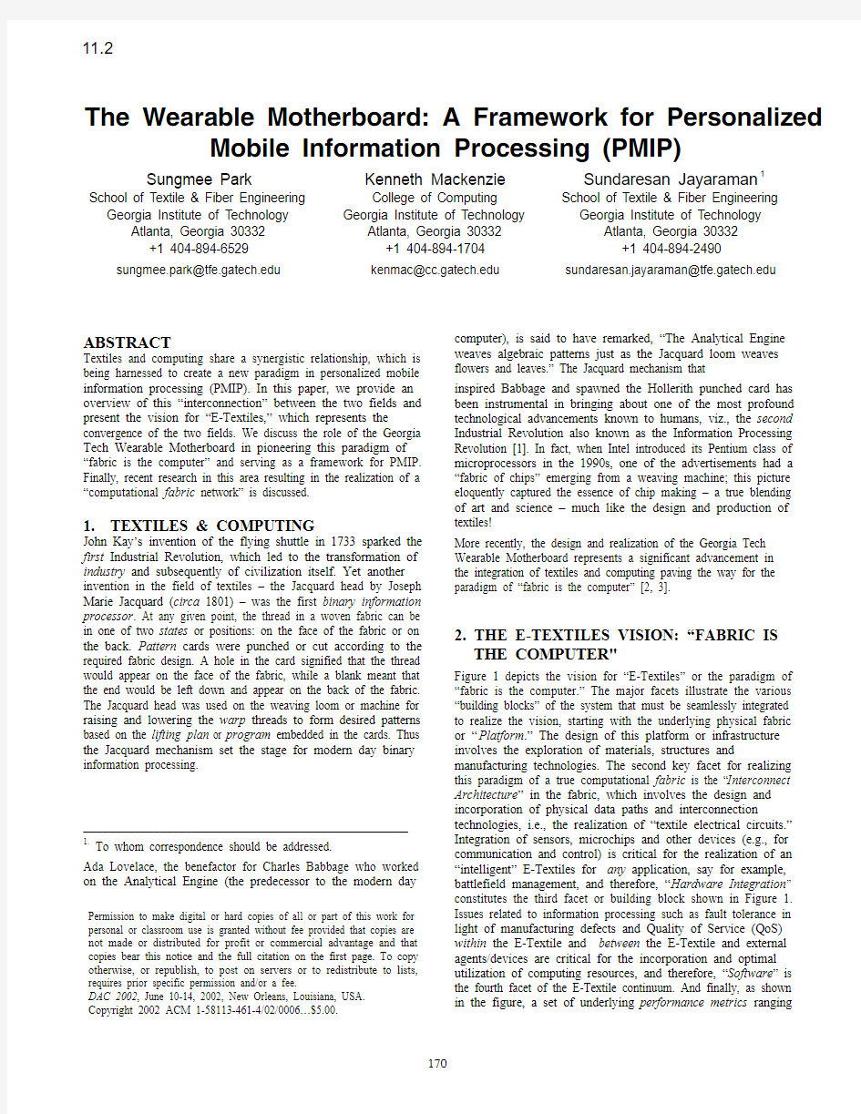
Figure 1 depicts the vision for “E-Textiles” or the paradigm of “fabric is the computer.” The major facets illustrate the various “building blocks” of the system that must be seamlessly integrated to realize the vision, starting with the underlying physical fabric or “Platform.” The design of this platform or infrastructure involves the exploration of materials, structures and manufacturing technologies. The second key facet for realizing this paradigm of a true computational fabric is the “Interconnect Architecture” in the fabric, which involves the design and incorporation of physical data paths and interconnection technologies, i.e., the realization of “textile electrical circuits.” Integration of sensors, microchips and other devices (e.g., for communication and control) is critical for the realization of an “intelligent” E-Textiles for any application, say for example, battlefield management, and therefore, “Hardware Integration” constitutes the third facet or building block shown in Figure 1. Issues related to information processing such as fault tolerance in light of manufacturing defects and Quality of Service (QoS) within the E-Textile and between the E-Textile and external agents/devices are critical for the incorporation and optimal utilization of computing resources, and therefore, “Software” is the fourth facet of the E-Textile continuum. And finally, as shown in the figure, a set of underlying performance metrics ranging
Permission to make digital or hard copies of all or part of this work for personal or classroom use is granted without fee provided that copies are not made or distributed for profit or commercial advantage and that copies bear this notice and the full citation on the first page. To copy otherwise, or republish, to post on servers or to redistribute to lists, requires prior specific permission and/or a fee.
DAC 2002, June 10-14, 2002, New Orleans, Louisiana, USA. Copyright 2002 ACM 1-58113-461-4/02/0006…$5.00.
11.2
from the physical dimensions (of the resulting structure/system) to costs, manufacturability and data flow rates must be utilized to assess the successful realization and performance of the desired E-Textile. Thus this paradigm of “fabric is the computer” represents a fascinating area of research that fosters, nay necessitates, collaboration amongst scientists and engineers from a variety of disciplines including textiles, computing and communications, sensor technologies and application domains (e.g., medicine, space, military).
Figure1. The E-Textiles Vision
3. THE WEARABLE MOTHERBOARD
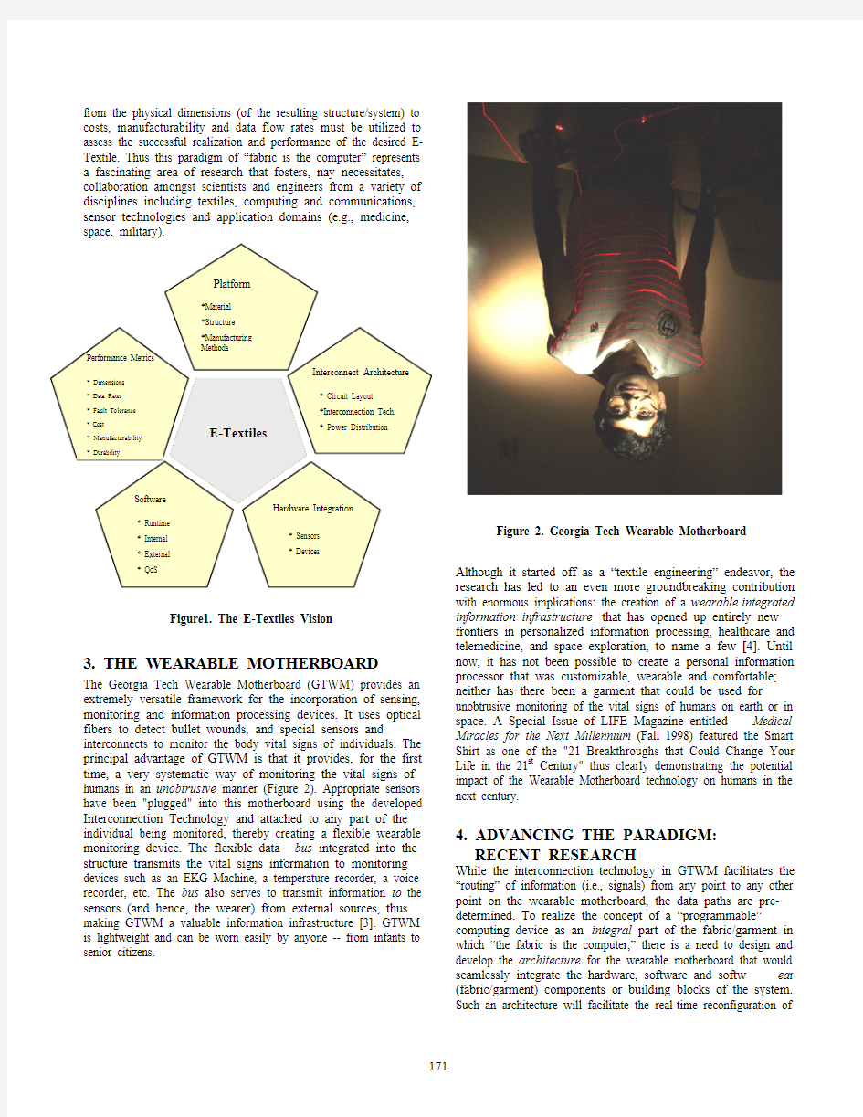
The Georgia Tech Wearable Motherboard (GTWM) provides an extremely versatile framework for the incorporation of sensing, monitoring and information processing devices. It uses optical fibers to detect bullet wounds, and special sensors and interconnects to monitor the body vital signs of individuals. The principal advantage of GTWM is that it provides, for the first time, a very systematic way of monitoring the vital signs of humans in an unobtrusive manner (Figure 2). Appropriate sensors have been "plugged" into this motherboard using the developed Interconnection Technology and attached to any part of the individual being monitored, thereby creating a flexible wearable monitoring device. The flexible data bus integrated into the structure transmits the vital signs information to monitoring devices such as an EKG Machine, a temperature recorder, a voice recorder, etc. The bus also serves to transmit information to the sensors (and hence, the wearer) from external sources, thus making GTWM a valuable information infrastructure [3]. GTWM is lightweight and can be worn easily by anyone -- from infants to senior citizens.
Figure 2. Georgia Tech Wearable Motherboard
Although it started off as a “textile engineering” endeavor, the research has led to an even more groundbreaking contribution with enormous implications: the creation of a wearable integrated information infrastructure that has opened up entirely new frontiers in personalized information processing, healthcare and telemedicine, and space exploration, to name a few [4]. Until now, it has not been possible to create a personal information processor that was customizable, wearable and comfortable; neither has there been a garment that could be used for unobtrusive monitoring of the vital signs of humans on earth or in space. A Special Issue of LIFE Magazine entitled Medical Miracles for the Next Millennium (Fall 1998) featured the Smart Shirt as one of the "21 Breakthroughs that Could Change Your Life in the 21st Century" thus clearly demonstrating the potential impact of the Wearable Motherboard technology on humans in the next century.
4. ADVANCING THE PARADIGM: RECENT RESEARCH
While the interconnection technology in GTWM facilitates the “routing” of information (i.e., signals) from any point to any other point on the wearable motherboard, the data paths are pre-determined. To realize the concept of a “programmable” computing device as an integral part of the fabric/garment in which “the fabric is the computer,” there is a need to design and develop the architecture for the wearable motherboard that would seamlessly integrate the hardware, software and softw ea r (fabric/garment) components or building blocks of the system. Such an architecture will facilitate the real-time reconfiguration of
the system ‘building blocks’ that would lead to the realization of a truly adaptive and responsive wearable computational fabric system thus resulting in pervasive/invisible information processing.
Research is being carried out to explore the feasibility of creating such an E-Textile to demonstrate PMIP using the wearable motherboard. As the first step, the information from one or more sensors (e.g., electrocardiogram or voice) is being routed through the “soft” interconnects in the fabric to the desired output points using FPGAs (field-programmable gate arrays).
4.1 The Approach
A "switchbox" approach has been chosen to combine the conductive fibers of an E-Textile into a programmable network. The switchbox approach is to treat the conductive fibers like the wiring resources in an FPGA to which switching components can be added at strategic intersections. A key problem in the switchbox architecture is to tolerate loose manufacturing tolerances since it is not known in advance as to which wires are connected to which pins on the switchbox. Therefore, we suggest a design for a single-chip, integrated switchbox and, simultaneously, build a demonstration prototype using off-the-shelf components.
4.2 The Architecture
The architecture consists of conductive fibers in the fabric plus switchboxes, which are affixed (like buttons) atop intersections of the fibers. The architecture leads to three decisions [5]:
1. Placement of switchboxes;
2. Complexity of wiring; and
3. Complexity of switchboxes.
4.2.1 Placement of Switchboxes
The manufacturing tolerance for placement of switchboxes can be tight or loose.
a. Exact: switchboxes placement tolerance could be good enough
to place switchbox contacts atop particular conductive
fibers. This option requires precise manufacturing
tolerance or a large fiber-to-fiber pitch.
b. Close: the placement tolerance is a small factor larger than the
fiber pitch.
c. Random: switchbox placement is uncontrolle
d.
Since one of the overall objectives of this research is to produce such E-Textiles in a typical manufacturing environment, option (b) has been chosen since it is similar to fastener placement in apparel manufacturing. We assume that a switchbox covering several fibers can be placed such that it will contact a particular fiber but we do not know which switchbox contact will actually make the contact. 4.2.2 Complexity of Wiring
The conductive fibers in the E-Textiles can be continuous or cut at each switchbox.
a. Continuous fibers are easily manufactured.
b. Cut fibers lead to a richer interconnect with higher local
bandwidth between points in the fabric.
From a manufacturing standpoint, option (a) is easier and so fibers (yarns) that are continuous in the fabric have been chosen. We address restricted bandwidth by making the switchboxes more capable.
4.2.3 Complexity of Switchboxes
Switchboxes can be built at multiple "grain" sizes, i.e., how much computing resources are concentrated at the intersection of two fibers. We distinguish grain sizes based on the extent to which the switchbox component participates in topology discovery and configuration.
a. Minimalist, e.g., a single transistor or gate at a single
intersection: configuration is managed and performed externally although configuration state may be stored at the intersection, e.g., using technology analogous to floating gates in VLSI.
b. Communication-capable: the switchbox can communicate
with, and perform local configuration on behalf of, an external agent. Global configuration is managed externally.
c. Self-configuration-capable: the switchbox contains enough
processing power to participate in a distributed, global configuration algorithm.
We chose option (b), switchboxes capable of self-configuring to the point of establishing communication with an external agent which then manages global configuration.
Thus, we chose an architecture for the computational fabric in which the electronic elements are of moderate capability, are placed deliberately, but inexactly, and without making cuts in the fabric.
4.3 Technical Issues and Decisions
We have identified three key issues with our architecture and proposed solutions for them. They are: power distribution, configuration information distribution and automatic discovery of topology.
4.3.1 Power Distribution
Power distribution is difficult with inexact placement of components because power connections are usually distinguished from signal connections. We believe it may be possible to power ordinary integrated circuits via any pin using diode structures similar to existing static discharge protection structures. However, for the first demonstration prototype, we use distinguished power wires in the fabric by providing enough spacing to account for our placement tolerance (unlike signal wires).
4.3.2 Configuration Information Distribution
Configuration information distribution is similarly difficult because FPGAs and microcontrollers typically expect
configuration information to be presented on specific pins. This problem is not fundamental, however. We use an FPGA-within-an-FPGA technique to address the problem: we use a statically-defined FPGA that includes configurable elements within it. Thus we can emulate an FPGA that accepts configuration information from multiple (initially any) pins.
4.3.3 Discovery of Topology
Topology discovery can be externally or internally managed and sequential or parallel. We adopt a conservative approach: an
external agent sequences the discovery and the discovery proceeds sequentially from the element nearest the external agent.
4.4 Realization of the Architecture
The first step in realizing the architecture through a prototype demonstration has been to define an ideal switchbox element that we believe is buildable using current technology. The next step is to begin prototyping an approximation to the ideal device to serve as a proof-of-concept.
The ideal device is an EEPROM-based FPGA in a custom plastic package that contains insulation-displacement-style connectors instead of pins. The device would be press-fit onto the fabric like a fastener. Once configured, the device would provide digital communications between points on the fabric including sensors, effectors and communications devices that attach to the switchboxes or directly to conductive fibers that cross a switchbox.
The prototype device is a 2.8"x1.8" protoboard containing a small EEPROM-based FPGA (Altera EPM7160S) plus a microcontroller (Motorola HC11) as shown in Figure 3. The board connects to the fabric using two standard 26-pin insulation-displacement connectors (IDCs) ordinarily used for ribbon cable. The fabric in Figure 3 contains conductive fibers at a density of 10 per inch. The 26-pin IDCs contain contacts at a pitch of 20 to the inch. We find that every fiber makes contact with some contact in the connector but the position of that contact is off by up to two positions in the connector. In the connector, the leftmost and rightmost fibers are dedicated to power buses while the center fibers carry signals, up to seven signals in each
direction.
Figure 3. Prototype board, 2.8"x1.8", containing the FPGA
and microcontroller. Site-specific
sensor/effector/communication devices attach as “daughtercards.”
The chosen FPGAs were physically integrated into the fabric (see Figure 4). Software was developed to demonstrate the “in-fabric” network. One of the FPGAs communicated with an external agent (a Linux-based personal computer) that was responsible for managing the global configuration of the FPGAs in the fabric by sequencing the “discovery” in the fabric beginning with that initial FPGA.
Figure 4. The PMIP Network in a Fabric
Two software modules were created; the first was to “demonstrate” the pin-connection discovery algorithm implemented in the system to identify the connections between the various pins on the FPGAs in the fabric and to display the connection paths. This enables discovery of the interconnects on the fly after the manufacturing has been carried out and there is no
a priori knowledge of the specific connections between the elements in the fabric. The second module discovers the connections and displays the paths on the screen as the discovery process proceeds when the FPGA is powered. To demonstrate the flow of information in the fabric network through the soft interconnects, a potentiometer was attached as a daughterboard to one of the FPGAs and whenever it was “twiddled” (see Figure 4), the resulting change is displayed on the screen (Figures 5 and 6). This recent effort demonstrates the feasibility of realizing a programmable network in a fabric through soft interconnects and paves the way for the continued exploration of the “fabric is the computer” paradigm pioneered by the Georgia Tech Wearable Motherboard.
Figure 5. The Steady State Display
Figure 6. Flow of Information through the PMIP Fabric. CONCLUDING REMARKS
A well-designed information processing system should facilitate the access of information A nytime, A nyplace by A nyone – the three A s. The ‘ultimate’ information processing system should not only provide for large bandwidths, but also have the ability to see, feel, think, and act. In other words, the system should be totally ‘customizable’ and be in tune with the human. Of course, clothing is probably the only element that is ‘always there’ and in complete harmony with the individual (at least in a civilized society!). And, textiles provide the ultimate flexibility in system design by virtue of the broad range of fibers, yarns, fabrics, and manufacturing techniques that can be deployed to create products for desired end-use applications. A new avenue of research and exploration has opened up for the development of an integrated “textile-computing” system that can serve as a true information processing framework with the ability to sense, feel, think and act based on the end-user stimuli and/or the operational environment. This “fabric is the computer” paradigm exemplified by the Georgia Tech Wearable Motherboard demonstrates the feasibility of realizing personalized mobile information processing (PMIP) and gives new meaning to the term human-machine symbiosis in the context of pervasive/invisible computing. ACKNOWLEDGEMENTS
The authors would like to thank Dr. Bob Graybill of DARPA for providing funding under Contract # F30602-00-2-0564 for the current research exploring the paradigm of “fabric is the computer.” Initial research on the Wearable Motherboard was carried out under Contract # N66001-96-C-8639 from the US Department of Navy.
REFERENCES
[1] Jayaraman, S., "Designing a Textile Curriculum for the
'90s: A Rewarding Challenge", Journal of the Textile
Institute, 1990, 81(2) 185-194.
[2] The Georgia Tech Wearable Motherboard?: The
Intelligent Garment for the 21st Century,
https://www.360docs.net/doc/f38979751.html,.
[3] Gopalsamy, C., Park, S., Rajamanickam, R., and
Jayaraman, S, “The Wearable Motherboard : The First
Generation Of Adaptive And Responsive Textile
Structures (ARTS) For Medical Applications”, Journal of
Virtual Reality, 1999, 4:152-168.
[4] Park, S., Gopalsamy, C., Rajamanickam, R., and
Jayaraman, S., "The Wearable Motherboard?: An
Information Infrastructure or Sensate Liner for Medical
Applications", in Studies in Health Technology and
Informatics, IOS Press, Vol. 62, pp. 252-258, 1999.
[5] Mackenzie, K., Hudson, D., Maule, S., Park, S., and
Jayaraman, S., “A Prototype Network Embedded in
Textile Fabric,” Proceedings of CASES 2001,
International Conference on Compilers, Architecture and
Synthesis for Embedded Systems, November 16-17,
Atlanta, Georgia, pp. 188-194, 2001.
最详细一键GHOST优盘版教程
有的时候,系统进不了,这时除了用光盘外,还可以用U盘进入GHOST软件中进行还原系统, 一、安装: 所谓"优盘",本软件指所有USB磁盘,包括普通U盘、MP3/MP4播放器、USB读卡器(含存储卡)、USB 移动硬盘。 为叙述方便,下文统一称之为"U盘".另外,对于容量几乎没有要求,16MB或以上即可. 下载,解压。 安装步骤: 1_初始化(一般情况下,U盘出厂时已经做好了初始化,此步可跳过.) 初始化就是用U盘芯片厂商提供的量产工具/使用者管理工具,对U盘进行低级格化等操作, 当U盘有严重问题时,能让U盘起死回生;管理工具的分区/格式化功能可提高引导成功率. 相关下载: https://www.360docs.net/doc/f38979751.html,/soft/SoftList/Catalog_31_SoftTime_Des c_1.html 使用方法: 略(各个U盘采用芯片都不一样,所以使用的工具也不一样,一般都自带说明.) 2_引导设置(2010版新方法,不同于2009以及更早版本,多数步骤是必须的.) 相关文件: 2_引导设置.exe 具体步骤: 如下.
(1)完全格式化:插入U盘->双击"我的电脑(计算机)"->右击U盘->格式化->"文件系统"选择 FAT32或FAT或NTFS(不要选exFAT)->卷标输入GHOST->不要选"快速格式化"->开始. 注意:格式化会删除所有数据,请事先做好数据文件的备份。 (2)选择目标磁盘:重插U盘,双击"2_设置引导.exe"即可进入BOOTICE主界面,【目标磁盘】 下会自动检测到本地硬盘和USB磁盘,一般情况会自动定位到首个U盘,如果没有自动定位 到你的U盘,请手动选择U盘即可.主界面下方有四个按钮,其中【主引导记录】,【分区引导记录】, 【重新格式化】接下来我们都会用到. (3)【重新格式化】->USB-HDD模式(单分区)->下一步->FAT32(或FAT或NTFS),注意:必须与 "完全格式化"时候的"文件系统"格式相同->确定->确定->关闭(返回主界面),重插U盘.
教师计算机校本培训教学方案教育教案
教师计算机校本培训教案 培训时间:2012年10月15日—2012年10月19日 本次校本培训技术能力目标 1.硬件操作技能: ①了解和掌握计算机的基本功能和操作,常用计算机输入、输出设备的基本操作(如常用的键盘、鼠标、光驱、U盘、打印机、显示器等); ②了解计算机硬件系统的基本组成与结构; ③会正确开关计算机;能够正确使用校内所配备的各类电教教学设备。 ④知道常用硬件媒体设备种类与功能(如声音、图形、图像、动画、视频,每种设备适用于何种环境以及适用于传递哪一类型的信息); ⑤了解多媒体硬件技术在教学中的发展趋势。 2.软件使用技能: ①熟悉常用计算机操作系统用户界面和基本操作(如文件管理、启动运行应用程序); ②能使用文字处理软件(如Word等)熟练编排所任教学科的试卷; ③会使用电子表格软件(如Excel等)进行较高级的数据分析、筛选及其它数学运算; ④熟练使用多媒体课件制作工具(如PowerPoint等)制作课件,能将声音、图片、视屏、动画等各类素材进行整合运用。 ⑤会使用Word办公软件进行文字输入并进行简单的内容、格式编排和打印; ⑥能使用多媒体课件进行教学; ⑦会在互联网上浏览信息,搜索教育、教学资源,会在网上进行上传、下载等操作。 3.信息化教学素养:能利用信息技术构建有利于学生学习的教学环境;编制适于所任教学科信息化教案及课堂实施方案;将各类教育资源与日常教学进行整合并合理应用,善于利用教育资源突破教育教学重、难点,激发学生学习兴趣,提高教育教学质量;能够帮助学生有效地运用信息技术进行学习,指导学生获取信息化学习资源(如通过网络获取学习资源或相关辅导材料,利用网络教学平台进行学习)。 一、计算机基础知识介绍 一、计算机的组成 1. 硬件系统 硬件系统即为外部设备,就是除了主机以外的所有设备。外部设备的作用是辅助主机的工作,为主机提供足够大的外部存储空间,提供与主机进行信息交换的各种手段。 计算机的常用外设通常包括键盘、鼠标、显示器、打印机、扫描仪、音箱等。 移动设备包括,CD光盘、移动硬盘、U盘。 U盘是我们工作中用的比较多的移动设备,在不用U盘的时候立即将U 盘安全退出。U盘较长时间放在电脑上会烧坏U盘,从而导致资料丢失。建议大家U盘中的重要资料在电脑上备份一下。
经典功率谱估计方法实现问题的研究
1 随机信号的经典谱估计方法 估计功率谱密度的平滑周期图是一种计算简单的经典方法。它的主要特点是与任 何模型参数无关,是一类非参数化方法[4]。它的主要问题是:由于假定信号的自相关函数在数据观测区以外等于零,因此估计出来的功率谱很难与信号的真实功率谱相匹配。在一般情况下,周期图的渐进性能无法给出实际功率谱的一个满意的近似,因而是一种低分辨率的谱估计方法。本章主要介绍了周期图法、相关法谱估计(BT )、巴特利特(Bartlett)平均周期图的方法和Welch 法这四种方法。 2.1 周期图法 周期图法又称直接法。它是从随机信号x(n)中截取N 长的一段,把它视为能量有限x(n)真实功率谱)(jw x e S 的估计)(jw x e S 的抽样. 周期图这一概念早在1899年就提出了,但由于点数N一般比较大,该方法的计算量过大而在当时无法使用。只是1965年FFT 出现后,此法才变成谱估计的一个常用方法。周期图法[5]包含了下列两条假设: 1.认为随机序列是广义平稳且各态遍历的,可以用其一个样本x(n)中的一段 )(n x N 来估计该随机序列的功率谱。这当然必然带来误差。 2.由于对)(n x N 采用DFT ,就默认)(n x N 在时域是周期的,以及)(k x N 在频域是周期的。这种方法把随机序列样本x(n)看成是截得一段)(n x N 的周期延拓,这也就是周期图法这个名字的来历。与相关法相比,相关法在求相关函数)(m R x 时将 )(n x N 以外是数据全都看成零,因此相关法认为除)(n x N 外 x(n)是全零序列,这种处 理方法显然与周期图法不一样。 但是,当相关法被引入基于FFT 的快速相关后,相关法和周期图法开始融合。通过比较我们发现:如果相关法中M=N ,不加延迟窗,那么就和补充(N-1)个零的周期图法一样了。简单地可以这样说:周期图法是M=N 时相关法的特例。因此相关法和周期图法可结合使用。 2.2 相关法谱估计(BT )法
第11章 项目分析与评估
第1章 项目分析与评估 本章问题:1. 什么是预测风险?为什么要分析价值来源? 2.什么是情景分析、敏感性分析和模拟分析?它们的优缺点是什么? 3.怎样进行会计保本点分析? 4.经营杠杆是什么含意?怎样计算? 1.预测风险 1.1 预测风险 由于预测现金流量的错误导致我们做出糟糕决策的可能性,叫做预测风险或估计风险。也就是错误估计或预测现金流量而导致决策失误引起的可能损失。 1.2 价值来源分析 价值来源分析就是竞争优势分析。根据完全市场理论,在完全市场条件下,企业只能获取正常利润,要取得NPV为正的项目是不可能的,在成熟市场经济条件下,企业寻求NPV为正的项目机会较少。然而,在现实市场经济活动中,依然存在着一些投资机会。竞争优势可以理解为垄断优势——差异化优势。根据波特的竞争优势理论,差异化是企业价值的真正来源。 所以,价值来源分析首先是差异化分析。差异可分为产品(服务)差异和成本差异化优势。 其次,市场竞争程度分析。 再次,潜在竞争分析。 2. 情景分析和其它条件分析 1.1基本情况分析 基本情况分析实际上是点分析。例p203,习题11-5。 1.2 情景分析
情景分析是一种“如果——结果”会怎样的分析,实际上是一种区间分析。如果“乐观”结果会怎样?如果“悲观”结果会怎样?例 p204,习题11-5。 1.3 敏感性分析 敏感性分析实际上是一种因素分析。可分为单因素分析和多因素分析两种。在于找出项目成败的关键因素,并进行专题分析。例p205,习题11-5。 1.4 模拟分析 将区间分析与因素分析结合起来,就是模拟分析,即尽可能仿真现实环境进行仿现场分析。使用EXCEL是仿真分析成为可能。
2013计算机常用工具软件2(考试)
2013计算机常用工具软件2(考试) 1单项选择 1.下列不是网页浏览工具的是()。 AIE9.0 B火狐 C遨游 D豪杰大眼睛 正确答案:D 2.电脑硬件最基本的信息保存在()中。 AROM BBIOS CCMOS DRAM 正确答案:C 3.HyperSnap-DX,不能截取() A软件操作界面 B活动窗口 C特定区域 D视频文件 正确答案:D 4.不是搜索引擎的网站() A百度 B搜狐 C网易 DGoogle 正确答案:C 5.在使用工具软件的过程中,可以执行〖帮助〗菜单命令来获得帮助信息,通过按()键,也可以打开帮助窗口。 AF1 BShift+H CF4 DAlt+F 正确答案:A 6.类似thunder://QUFodHR41OTo4k4LnJhclpa的链接必须使用()下载 A迅雷 B快车 C旋风
D电驴 正确答案:A 7.卸载软件的方法最好使用() A直接删除 B不予理睬 C删除快捷方式 D利用软件的卸载程序 正确答案:D 8.要将多个文件打包成一个文件,应使用()软件。 AWinRAR BACDSee CInternetExplorer DMicrosoftWord 正确答案:A 9.下列选项中,错误的压缩文件方法是()。 A将文件图标拖放到WinRAR程序快捷图标上 B打开WinZip程序,将文件拖放到程序界面中 C打开“我的电脑”窗口,使用“文件”菜单命令 D右击文件,从快捷菜单中选择压缩命令 正确答案:C 10.下列工具软件中()是用于检测计算机的。 AWinRAR BEasyRecovery CNortonGhost DSiSoftwareSandra 正确答案:D 11.关于Spx截图工具,下列叙述错误的是()。 A可以截取活动窗口 B要以截取特定区域 C可以截取视频文件 D不可以截取视频文件 正确答案:C 12.下列类型的软件中,功能没有任何限制且又不需要付费的是()。A共享软件 B正版软件 C免费软件 D试用软件
项目后评估工作管理办法
项目后评估工作管理办法
目录 第一章总则 (2) 第二章管理职责与分工 (4) 第三章对象与分类 (5) 1、属于公司投资、开发、经营、管理的房地产项目; (5) 2、项目85%以上的建筑面积已整体完成竣工验收备案; (5) 3、投资管理中心根据项目具体情况规定的条件。 (5) 第四章工作组织与流程 (6) 第五章资料收集 (8) 第六章评估内容 (10) 第三十二条后评估工作应包括但不限于以下方面的内容: (10) 第七章合作项目的后评估 (12) 第八章成果应用 (12) 第九章保密与存档 (13) 第十章罚则 (14) 第十一章附则 (14) 第四十八条本规定由投资管理中心负责修订和解释。 (14)
第一章总则 第一条为全面规范公司房地产项目后评估工作,系统性地总结项目开发运营的经验与教训,提高公司未来项目投资决策、模式选择、运营管理、财务核算、配套服务、管理创新的水平,特制定本办法。 第二条本办法适用于XX房地产(集团)股份有限公司(以下称“XX地产”)各级房地产开发公司以及纳入XX地产经营管理体系内的其他主体(以下简称“公司”)所投资、开发、经营、管理的房地产项目的后评估工作。 第三条本办法所称的“后评估”是指公司投资、开发、经营、管理的房地产项目,在其开发销售工作基本结束后,运作主体对项目开发运营实施全过程回顾、分析,从而总结项目开发的经验、教训的一系列工作。 第四条后评估工作的开展须遵循以下原则: 1、客观性:后评估工作成果须真实反映项目运作的实际情况,所做的各项分析必须以真实数据、材料为依据; 2、全面性:后评估是对项目开发运营全过程的综合评价,必须涉及到项目从投资立项到交付使用过程中发生的主要业务,并据此得出综合、全面的评价;
一键GHOST光盘版安装刻录使用图解
一键GHOST光盘版安装、刻录、使用图解 2009年12月06日星期日14:15 一、刻录: 1、准备好空白光盘,用油性记号笔在盘面上写上软件名称和版本号,以防时间久了与其它光盘混淆. 2、下载-> 解压,注意:如果默认打开程序是WINRAR,请不要双击打开文件"一键GHOST光盘版.ISO", 正确方法是:是用Nero 或UltraISO 9.2 以上版本打开"一键
GHOST光盘版.ISO", (一)基本刻录方法(不集成GHO映像):以Nero 为例(当然也可以用UltraISO) : 所谓“不集成GHO映像”就是仅仅刻录一键GHOST光盘版.ISO,可实现一键恢复C盘(来自硬盘)等功能, 不能实现一键恢复C盘(来自光盘)功能。由于占用空间很少(5M 到6M),1张CD即可(如果怕浪费可加入其它文件,但不推荐使用Nero,推荐使用UltraISO)。 1、运行Nero StartSmart -> 复制与备份-> 将映像刻录到光盘上
2、选择"文件类型"为"图像文件(*.nrg,*.iso,*.cue)" -> 找到"一键GHOST光盘版.ISO"->"打开" 3、放入CD空白光盘(CD-R)到刻录机(或康宝)里-> 选择"写入速度"较慢一些,以免刻录失败 (如,全速是52x可选择32x,如果硬件配置较低,应选16x或8x) -> 点"下一步",
以后就是等待了...刻录成功,退出NERO. (二)高级刻录方法(集成GHO映像): 所谓“集成GHO映像”就是将保存到硬盘上的GHOST映像刻录到CD或DVD空白光盘里,利用 一键GHOST光盘版提供了一键恢复C盘(来自光盘)功能实现的一种更加安全的恢复方案。 由于C盘已用空间每台电脑情况有所不同,致使生成的映像大小也不一样,所以往往需要不止1张CD或DVD。 但必须事先严格按照以下步骤刻录才能使用(试举一例): 1、准备:使用一键GHOST硬盘版->中文向导->备份向导功能,将C盘备份到D盘根
如何删除双系统启动项中的一项(精)
如何删除双系统启动项中的一项 第一种办法: 如你的电脑以前安装了双系统,就是把另一个系统删除了,在启动菜单里启动项仍然存在, 虽不影响使用,但看起来不舒服,如何删除双菜单呢? 进入 Windows XP ,打开“ 我的电脑” 属性,选择“ 高级” 选项卡,单击“ 启动和故障恢复” 选项的“ 设置” ,在弹出的对话框中单击“ 编辑” ,会自动打开 boot.ini 这个文件。 boot.ini 文件是个启动引导程序文件,装多系统或者重装系统的时候会用到它打开默认的情况下这个文件“c:\\boot.ini” 启动该文件。这个文件是隐藏的,准确路径是 c:\\boot.ini,可以用记事本打开这个路径,也可以在“ 运行” 中输入常用的方法是去掉隐藏后用记事本打开, “ 资源管理器”→“ 工具”→“ 文件夹选项”→“ 查看” 去掉“ 隐藏……” 前面的√ , “ 隐藏文件和文件夹” 选“ 显示……” 这样就去掉了隐藏,可以在 c:\\看到 boot.ini 文件了。 那要看你现在留的是什么系统了。如果是 XP 就很方便, 一般在系统分区里有个隐藏的文件 boot.ini 。一般标准的设置是“ [boot loader] timeout=30 default=multi(0disk(0rdisk(0partition(1\WINDOWS [operating systems] multi(0disk(0rdisk(0partition(1\WINDOWS="Microsoft Windows XP Professional" /noexecute=optin /fastdetect
利用经典谱估计法估计信号的功率谱(随机信号)
随机信号 利用经典谱估计法估计信号的功率谱
作业综述: 给出一段信号“asd.wav”,利用经典谱估计法的原理,通过不同的谱估计方法,求出信号的功率谱密度函数。采用MATLAB语言,利用MATLAB语言强大的数据处理和数据可视化能力,通过GUI的对话框模板,使操作更为简便!在一个GUI界面中,同时呈现出不同方法产生出的功率谱。 这里给出了几种不同的方法:BT法,周期图法,平均法以及Welch法。把几种不同方法所得到的功率谱都呈现在一个界面中,便于对几种不同方法得到的功率谱作对比。 一.题目要求 给出一段信号及采样率,利用经典谱估计法估计出信号的功率谱。 二.基本原理及方法 经典谱估计的方法,实质上依赖于传统的傅里叶变换法。它是将数据工作区外的未知数据假设为零,相当于数据加窗,主要方法有BT法,周期图法,平均法以及Welch法。 1. BT法(Blackman-Tukey) ●理论基础: (1)随机序列的维纳-辛钦定理 由于随机序列{X(n)}的自相关函数Rx(m)=E[X(n)X(n+m)]定义在离散点m上,设取样间隔为,则可将随机序列的自相关函数用连续时间函数表示为 等式两边取傅里叶变换,则随机序列的功率谱密度 (2)谱估计 BT法是先估计自相关函数Rx(m)(|m|=0,1,2…,N-1),然后再经过离散傅里叶变换求的功率谱密度的估值。即 其中可有式得到。 2. 周期图法 ●理论基础: 周期图法是根据各态历经随机过程功率谱的定义来进行谱估计的。在前面我们已知,各态历经的连续随机过程的功率谱密度满足
式中 是连续随机过程第i 个样本的截取函数 的频谱。对应在随机序列中则有 由于随机序列中观测数据 仅在 的点上存在,则 的N 点离散傅里叶变换为: 因此有随机信号的观测数据 的功率谱估计值(称“周期图”)如下: 由于上式中的离散傅里叶变换可以用快速傅里叶变换计算,因此就可以估计出功率 谱。 3.平均法: 理论基础: 平均法可视为周期图法的改进。周期图经过平均后会使它的方差减少,达到一致估计的目的,有一个定理:如果 , , , 是不相关的随机变量,且都有个均值 及其方差 ,则可以证明它们的算术平均的均值为 ,方差为 。 由定理可见:具有 个独立同分布随机变量平均的方差,是单个随机变量方差的 , 当 时,方差 ,可以达到一致估计的目的。因此,将 个独立的估计量经过算术 平均后得到的估计量的方差也是原估计量方差的 。 平均图法即是将数据 , , 分段求周期图法后再平均。例如,给定N=1000个数据样本(平均法适用于数据量大的场合),则可以将它分成10个长度为100的小段,分别计算每一段的周期图 ()()2 1001100,100(1) 1 ,1,2,```,10100 l j l n l G w X e l ω-=-= =∑ 然后将这10个周期图加以平均得谱估计值: ()() 10 100100,1 110l l G w G w ==∑ 由于这10小段的周期图取决于同一个过程,因而其均值相同。若这10个小段的周期图是统计独立的,则这10个小段平均之后的方差却是单段方差的 。
用优盘运行一键GHOST还原系统
用优盘运行一键GHOST还原系统 有的时候,系统进不了,这时除了用光盘外,还可以用U盘进入GHOST软件中进行还原系统, 一、安装: 所谓"优盘",本软件指所有USB磁盘,包括普通U盘、MP3/MP4播放器、USB读卡器(含存储卡)、USB移动硬盘。 为叙述方便,下文统一称之为"U盘".另外,对于容量几乎没有要求,16MB或以上即可. 下载,解压。 安装步骤: 1_初始化(一般情况下,U盘出厂时已经做好了初始化,此步可跳过.) 初始化就是用U盘芯片厂商提供的量产工具/使用者管理工具,对U盘进行低级格化等操作, 当U盘有严重问题时,能让U盘起死回生;管理工具的分区/格式化功能可提高引导成功率. 相关下载: https://www.360docs.net/doc/f38979751.html,/soft/SoftList/Catalog_31_SoftTime_Desc_1.html
使用方法: 略(各个U盘采用芯片都不一样,所以使用的工具也不一样,一般都自带说明.) 2_引导设置(2010版新方法,不同于2009以及更早版本,多数步骤是必须的.) 相关文件: 2_引导设置.exe 具体步骤: 如下. (1)完全格式化:插入U盘->双击"我的电脑(计算机)"->右击U盘->格式化->"文件系统"选择 FAT32或FAT或NTFS(不要选exFAT)->卷标输入GHOST->不要选"快速格式化"->开始. 注意:格式化会删除所有数据,请事先做好数据文件的备份。 (2)选择目标磁盘:重插U盘,双击"2_设置引导.exe"即可进入BOOTICE主界面,【目标磁盘】 下会自动检测到本地硬盘和USB磁盘,一般情况会自动定位到首个U盘,如果没有自动定位 到你的U盘,请手动选择U盘即可.主界面下方有四个按钮,其中【主引导记录】,【分区引导记录】, 【重新格式化】接下来我们都会用到.
删除双系统中的一个启动(精)
如何删除双系统启动项中的一项第一种办法:如你的电脑以前安装了双系统,就是把另一个系统删除了,在启动菜单里启动项仍然存在,虽不影响使用,但看起来不舒服,如何删除双菜单呢?进入Windows XP,打开“我的电脑”属性,选择“高级”选项卡,单击“启动和故障恢复”选项的“设置”,在弹出的对话框中单击“编辑”,会自动打开boot.ini这个文件。 boot.ini 文件是个启动引导程序文件,装多系统或者重装系统的时候会用到它打开默认的情况下这个文件“c:\\boot.ini”启动该文件。这个文件是隐藏的,准确路径是c:\\boot.ini,可以用记事本打开这个路径,也可以在“运行”中输入常用的方法是去掉隐藏后用记事本打开,“资源管理器”→“工具”→“文件夹选项”→“查看”去掉“隐藏……”前面的√,“隐藏文件和文件夹”选“显示……”这样就去掉了隐藏,可以在c:\\看到boot.ini文件了。那要看你现在留的是什么系统了。如果是XP就很方便,一般在系统分区里有个隐藏的文件boot.ini。一般标准的设置是“ [boot loader] timeout=30 default=multi(0disk(0rdisk(0partition(1\WINDOWS [operating systems] multi(0disk(0rdisk(0partition(1\WINDOWS="Microsoft Windows XP Professional" /noexecute=optin /fastdetect ”。上面的“multi(0disk(0rdisk(0partition……”是说明磁盘的第一个分区是XP系统。如果是双系统下面就会多一行,删了就可以变单系统启动菜单了。如:[boot loader] timeout=10 default=multi(0disk(0rdisk(0partition(1\WINDOWS [operating systems] multi(0disk(0rdisk(0partition(1\WINDOWS="Microsoft Windows XP Professional" /fastdetect c:\geldr=一键还原精灵专业版最后行:“c:\geldr=一键还原精灵专业版”就是第二个启动项。第二种办法:对于Windows 7我想目前很多用户是在双系统的情况下启用的,那么如何卸载双系统下面的Windows 7呢?下面笔者整理了一个小技巧仅供各位需要卸载Windows 7的用户参看。 1. 插入刻好的 Windows 7 安装光盘(或者用虚拟光驱加载Windows 7镜像。 2. 依次点击“开始”-“运行”,弹出命令行窗口。 3. 在命令行窗口中输入 X:\boot\bootsect.exe /nt52 all /force ,然后按 Enter。(注:X:\代表你的光驱盘符,或者虚拟光驱盘符。例如,如果 DVD 驱动器号是 F,则键入 F:\boot\bootsect.exe /nt52 ALL /force。 4. 弹出 Windows 7 安装光盘(或者在虚拟光驱中卸载ISO镜像文件。 5. 重新启动计
一键GHOST 常见问题 FAQ
一键GHOST 常见问题FAQ * "一键备份系统"的映像保存在什么位置?有何优点?怎样进行打开等操作 答:(1)保存位置:第一硬盘最后一个分区:\~1\C_PAN.GHO (2)~1的优点:此文件夹在FAT分区下资源管器中完全隐藏即使打开"显示所有文件"也不可见, 在NTFS分区下可防止删除,以防止病毒的恶意行为或用户的误操作. (3)高级操作:映像->打开/保护/管理/导出/导入/移动/删除.(详见"安装运行->硬盘版->四、其它功能) * "一键备份系统"只能备份到第1硬盘最后一个分区吗?能备份到其它分区吗? 答:当然能,只要使用"中文向导"->"备份向导",修改分区的值即可. 但要注意:“备份向导”做的备份只能用“恢复向导”恢复,不能用“一键恢复系统”恢复。 * 如何实现对整个硬盘的操作? 答:备份向导,恢复向导,对拷向导都可实现对整个硬盘的操作: 只需将第?分区的默认值清除即可. * GHOST11.2有何优点?11.5有什么优点? 答:11.0.2(简称11.2)的最突出的优点是兼容性好(向上兼容11.5映像,向下兼容8.3映像); 11.5的优点是支持某些新的系统特性. 硬盘版可永久性地切换到11.5: 设置-> 版本-> GHOST11.5 -> 确定. 硬盘版/光盘版/优盘版都可以通过临时手动选择"MS-DOS一级菜单"切换到11.5 * 怎样防止熊猫烧香等病毒对GHO映像的恶意删除或者防止误删除? 答:最有效的方法是最后分区采用NTFS格式(如果最后分区是FAT格式可将其格式化成NTFS 格式) 因为本软件会对NTFS下的~1文件夹加强防删处理. * 我想把GHO文件刻录到光盘,但生成的映像较大,一张光盘放不下,可以刻在第2,3..张光盘上吗? 答: 当然可以,详情请参看HELP.chm帮助文档->安装运行->光盘版->高级刻录方法 * 一键备份系统时出现错误(622)怎样解决? 答: 请保证你现在使用的是最新版本,另外注意: 1,如果光盘版/优盘版出现此错误,必须首先安装硬盘版.
分析日干旺衰
分析日干旺衰 易学爱好者都知道八字预测最关键的一步是分析日干旺衰,受古人的影响,易学爱好者都认为分析日干旺衰时,首先遵循“十干生旺死绝表”所规定的十个天干在十二月令中的旺衰状态论日干之旺弱,其次,看日干在年月日时四个地支中的旺衰状况,即:得令、得势、得助、得生。此法延用了千余年,然而,此法在实践中检验看并不准确,如何正确地分析日干旺衰呢? 八字中的日干是旺还是弱,就看八字中日干之外的七个字对日干的影响了。七个字均帮扶日干或日干多受帮扶,少受克泄耗,日干会很旺。七个字均克泄耗日干,少受帮扶或不受帮扶,日干肯定很弱。七个字中有的帮扶日干,有的克泄耗日干,如果帮扶日干的总力量大于克泄耗日干的总力量,日干以旺论,反之以日干弱论。 日干旺,旺到什么程度?日干弱,弱到什么程度,就看印比力量的总和与财官伤力量的总和相差多少了,差距大,日干就很旺或很弱。印比力量的总和与财官伤力量的总和越接近,此八字的组合就越吉,但也绝无双方力量相同的情况。因为年干、年支、时支离日干较远,对日干的影响自然就会稍小,月干、月支、日支、时干靠近日干,对日干的作用最直接,自然对日干的影响也稍大。对日干作用力的大小,不仅取决于每个字距离日干的远近,还取决于每个字自身力量的
大小。自身力量大的字,对日干的作用力就大;自身力量弱的字,对日干的作用力就小。这七个字中,月令的力量最大,根据涵辰的实践摸索,如果把所有加在日干上的七个字的力量,看作100分的话,月令独占50分! 这是决定日干旺衰的一个极重要的量的规定,有了这一点,便可以准确地判定日干旺衰了。 为什么月令对日干旺衰的影响决定50%,老老实实地说,涵辰从理论上也讲不清楚,只是在实践中摸索出这个量,并通过大量实践检验,准确无误。为了解决这个疑问,涵辰曾向天文知识中寻找答案,很遗憾,到目前仍然没有彻底解决,这也是本杂志目前不能填补天文 知识这一空白的一个遗憾! 既然月令对日干影响如此之大,如何看日干在月令中的旺弱呢 ? 只要月令是日干的印比,日干在本命局中就有了50%旺的可能,反过来,月令是日干的财官伤,日干在本命局中,就有了50%弱的可能。有了这个50%的判断后,日干究竟属旺还是属弱,有以下几种 情况: 1 、日干在月令中旺50%,若月干、日支、时干三项中再有一项帮扶日干,七个字中加在日干身上的帮身之力,就超过50%,日 干以旺论。 2 、日干在月令中弱 50%,若月干、日支、时干三项中再有一项克制日干,七个字中作用在日干身上的克泄耗之力,就会超过50 %,日干以弱论。
win7如何一键还原
win7如何一键还原 win7是现在使用人数比较多的系统之一,他的界面美观,开机和关机速度快,稳定安全,还有一些特效,这些对用户有一个很好的体验。系统有问题,用户就会使用一键还原,还原系统。那win7如何一键还原呢? 首先,我们看看win7自带的一键还原,他的使用方法: win7的系统备份还原功能就集成在这Windows RE中,全名叫做System Image Recovery,不再是XP系统比较鸡肋的系统还原功能,而是如同Ghost一样地可以通过制作镜像文件来还原系统。相比起Ghost,使用这个功能不需要安装额外的软件,属于系统自带功能,启动时按F8键即可进入操作界面,同样可以制作成启动U盘来进行还原操作。 制作系统备份文件 我们使用ghost来进行备份的话,需要首先下载安装ghost软件,然后再重启通过启动菜单进入ghost界面来进行备份设置,相关的技巧介绍网上有很多,说明这个操作对于很多电脑新手是比较复杂的。而在win7中,我们进行系统备份很简单,只需要进入控制面板的备份还原选项就可轻松搞定,而且可以备份多个分区,比如我们可以同时备份系统所在的分区和常用软件的分区,在还原的时候可以同时还原,免去重新安装软件的麻烦。 ●进入备份还原选项设置 从控制面板中依次选择“System and Security→Back up your computer”(系统备份还原选项,备份你的电脑),在这里选择“Create a system image”开始进行备份操作,相比起ghost,这要简单得多,而且我们可以选择把备份文件存放在磁盘的某一个分区中(必须和系统分区在同一个磁盘中);或者直接保存到光盘,当然,就目前来说还不现实,估计是win7为蓝光光驱做准备吧;还可以直接将备份保存到任意一台局域网中的计算机,这对于在局域网中的办公电脑来说比较合适。需要指出的是无法备份到FAT32格式的分区。默认设置下,创建系统映像时会自动包含操作系统所在的分区,如果没有什么疑问的话,单击右下角的“Start backup”按钮即可开始备份。 笔者笔记本的硬盘为西数320GB,5400转,16mb缓存,备份总大小为20GB的系统盘和软件安装盘所耗费的时间为17分钟,备份之后的文件大小为16.7GB,如果是台式机相信备份速度会更快。这个速度和ghost的速度差不多,但是压缩率稍微低了一点,目前的硬盘也非常便宜,多占用一点空间也不是大问题。系统映像创建完成之后,备份向导会提示是否创建一个系统修复介质,日后可以用来引导计算机,你可以根据实际情况作出决定。 ●选择备份文件存放位置
第十一章 项目比选与总评估
第十一章项目比选与总评估 第一节概述 在项目评估、选优过程中,按项目之间的经济关系可分为独立项目(方案)和相关项目(方案)。后者又可分为互斥项目(方案)和互补项目(方案)。在这里,项目和方案是可以通用的,为了方便,我们分别称之为独立项目、互斥方案和互补方案。 独立项目是指在经济上互不相关的项目,即接受或放弃某个项目,并不影响其他项目的取舍。 互斥方案是指同一项目的各个方案彼此可以相互代替。因此,方案具有排他性,采纳方案组中的某一方案,就会自动排斥这组方案中的其他方案。 方案之间有时也会出现经济上互补的问题。它们之间相互依存的关系可能是对称的,也可能是不对称的。例如:连铸连轧工艺把过去相对独立的钢材生产结合了起来,使生产过程大大简化,还降低了热耗,降低了成本,不仅对钢坯生产有利,也对轧钢生产有利。此外还存在着大量不对称的经济互补,例如:建造一座建筑物A和增加一个空调系统B,建筑物A本身是有用的,增加空调系统B后使建筑物A更有用,但不能说采用方案B也包括方案A,当然这种互补可以是负的。例如:在一江河渡区考虑两个方案,一个是建桥方案(方案A),另一个是轮渡方案(方案B),两个方案都是收费的。此时可以考虑的方案组是方案A、方案B和AB混合方案。在AB混合方案中,方案A的收入将因另一方案B的存在而受到影响。 经济上互补而又对称的方案可以结合在一起作为一个“综合体”来考虑。经济上互补而不对称的方案,如上述建筑物A和空调系统B,则可把问题转化为对有空调的建筑物(方案C)和没有空调的建筑物(方案A)这两个互斥方案的经济比较。 在无约束条件下,一群独立项目的决策是比较容易的,这时项目评价要解决的问题,是项目评价指标能否达到某一评价标准的问题。因为对于经济上彼此独立的常规项目(即逐年净现金流量只有一次由负值变为正值的变化,且流入总额大于流出总额的项目),用净现值法、净现值率法、内部收益率法等任何一种方法进行评价的结论都是一致的。例如:某项目的FNPV(i c)≥0、FNPVR(i c)≥0、FIRR≥i c,或者ENPV(i s)≥0、ENPVR(i s)≥0、EIRR≥i s,则该项目在财务上或经济上就认为可以考虑接受。但是在若干可采用的独立项目中,如果有约束条件(比如受资金限制),只能从中选择一部分项目实施,就出现了资金合理分配问题,通常要通过项目排队(独立项目按优劣排序的最优组合)来优选项目。关于独立项目的经济评价方法和评价指标在前面已经详细述及。本章着重论述有关项目排队和互斥方案的比较方法。 项目排队和方案比较是寻求合理的经济和技术决策的必要手段,也是项目评估工作的重要组成部分。 项目排队和方案比选的原则及注意事项: 1.项目排队和方案比选原则上应通过国民经济评价来确定。对产出物基本相同、投入物构成基本一致的方案进行比选时,为了简化计算,在不与国民经济评价结果发生矛盾的条件下,也可通过财务评价确定。但在进行方案比较中,必要时仍需考虑相关效益和相关费用。 2.方案比选应遵循效益与费用计算口径对应一致的原则。 3.方案比选应注意各个方案间的可比性。 4.项目排队和方案比选应注意在某些情况下,使用不同评价指标导致相反结论的可能
一键GHOST安装XP系统完整教程(图文版)
使用一键GHOST安装XP系统完整教程(图文) 为什么要写用GHOST安装系统,你可能会问,现在网上有很多GHOST系统,为什么不用其直接安装,非得这么麻烦呢。原因很简单,因为有时你不会天天带着光盘跑,在没有光盘的时候你也能轻松安装好系统,并且安装成功率100%。 您又会问,为什么这么说呀,难道用光盘还有可能安装不成功吗?是的,有不成功这种情况,有两种因素会导致这种情况的发生,一是光盘硬件问题读盘能力等,二是GHOST方面的软件兼容性问题也会导致光盘安装出现问题。 现在大家是不是觉得这个教程有必要了呢?好了,进入正题。 使用环境:原来装了系统,在系统不是特别好用的情况下使用本教程,方便,快捷。如果连系统都进不了,哪就不用试了,这种用光盘装就OK了,本站有相关光盘安装XP的教程。 前题条件:1,系统必须安装一键还原工具。系统本身是GHOST系统的,这种系统一般都会集成一键GHOST工具,不是安装GHOST系统的也不要紧。可以去网上下载一个或在这个链接下载:下载https://www.360docs.net/doc/f38979751.html,:8080/555/一键GHOST V2008.08.08 奥运版.rar下载后在WINDOWS桌面上安装好。 2,下载GHOST系统ISO文件。下载一个GHOST系统,下载后将其用RAR软件解压缩出来。只保留最大的哪个GHO文件(600多M)如下所示;注意该文件必须放在非系统安装盘,比如,你的系统安装在C盘,哪么这个文件你就可以放在D或E盘。
安装好一键GHOST工具后,请重启电脑,就会在启动的过程中出现如下图的选项,请用上下键操作将光标移到一键GHOST上面,按下回车键。
一台电脑怎么装win7和xp两个系统
我这边收藏了一些装机资料,跟楼主分享下: 双系统安装说明: 1、先装XP,再装Windows 7,最好不要反过来,不然XP不会把Windows 7的启动管理器给覆盖掉,会麻烦些。总之遵循从“低版本到高版本”的安装原则。 2、如果分区不够大,请用以下软件调整,但要慎重,详见: 推荐安装的操作系统: Windows XP SP3 VOL 简体中文专业版(微软原版)+ 正版密钥 Windows 7 简体中文旗舰版(MSDN原版)+ 激活方式 XP下硬盘安装Windows 7的详细说明: 1、XP装在C盘,Windows 7装在非C盘,例:E盘,该盘必须是NTFS格式的空白磁盘(如果某些数据没有彻底清除,装前请先快速格式化一次,以免安装过程出错),大小16G以上,建议20G。 2、把下载好的镜像放在非Windows 7安装盘,直接用WinRAR解压,得到一个文件夹,双击运行里面的setup,点"下一步",接着按提示做就行了,安装过程会重起几次,整个安装过程20分钟左右,不同配置安装时间会有差别。(特别提醒: 安装过程切不要选升级,“要选自定义”,然后选择你事先准备好安装Windows 7的那个磁盘,例:E盘。另外激活码先不填,直接点"下一步",安装完成后再用"激活工具"激活即可。) 3、安装完成后,重启你会看到两个选择菜单,第一个是“早期版本的Windows”即Windows XP;第二个是“Windows 7”,且开机默认进系统的是Windows 7,等待时间为30秒。至此,一个完美的双系统就这样产生了。 光盘安装Windows 7简要说明:(C盘已装XP情况下) 1、下载后先验证映像文件效验值,确认是微软原版系统后,再刻盘。 2、安装前先进BIOS,设置“光驱为第一启动项”,按F10保存重起。 3、刚重起时放入系统光盘,读取成功后,屏幕上显示“Press any key to boot from CD or DVD”此时快速按下“Enter键”,复制成功后自动进入安装界面,请选择“自定义安装”,再选择“你事先准备好安装Windows 7的那个磁盘(最好事先快速格式化过,无数据盘)”,例:E盘,然后点“下一步”......安装过程自动化,大概20多分钟后安装完毕,再进行简单的设置包括激活系统。 4、重启电脑改回“硬盘为第一启动项”。
一键GHOST 硬盘版 使用说明
一键GHOST 硬盘版使用说明 一、软件安装 执行安装文件:\一键GHOST硬盘版\一键GHOST硬盘版.exe。 按照默认选项安装即可。 二、启动软件 点击:开始→程序→一键GHOST→一键GHOST,运行该软件,出现下列界面。
三、工具栏说明 由于一键映像(c_pan.gho)是受特殊保护的,所以禁止一般用户在资源管理器里对其本身进行直接操作, 但为了高级用户或管理员便于对映像进行管理,因此提供专门菜单: ①、打开:如果默认映像存在则用GHOSTEXP打开它以用于编辑GHO,例如:添加、删除、提取GHO里的文件;如果默认映像不存在则直接打开GHOSTEXP。 ②管理:在资源管理器里直接对默认GHO进行直接操作,例如:手动导入、导出、移动或删除等操作。(限管理员使用) ③导入:将外来的GHO复制或移动到~1文件夹中,一般用于免刻录安装系统,例如,将下载的通用GHO或同型号其它电脑的GHO复制到~1里(原GHO的文件名任意,导入后会自动改名为c_pan.gho)。 ④导出:将一键映像复制(另存)到其它地方,例如,将本机的GHO复制到U盘等移动设
备,为其它同型号电脑“导入”所用,以达到共享的目的。 ⑤移动:将一键映像移动到其它地方,例如,再次一键备份时不想覆盖原来的GHO,可将前一次的GHO转移到其它位置。 除了上述操作,选择最上方菜单:映像,还有下列2个菜单选项: ⑥删除:将一键映像删除(文件夹~1不会被删除),一般不常用 ⑦保护:去掉或加上防删属性(仅最后分区为NTFS时有效),例如:点击“是”即可永久性的解除保护,以便于直接“管理”。(限管理员使用) 四、备份系统 备份系统可通过以下几种方式: ●一键备份系统,选择后点击“备份”,计算机将重起,自动进入GHOST,然后出现备份界面,勿须人为干涉。但此方式生成的备份文件,自动生成在计算机第一硬盘的最后一个分区下的隐藏文件夹:~1\C_PAN.GHO,此文件自动生成,无法看到,但可以通过上面工具栏中管理或打开来查看。 ●选择“中文向导”后点击“备份”,计算机将重起,自动进入GHOST的中文向导界面,根据提示可选择镜像文件所存的分区。 ●选择GHOST11.2,或者在启动计算机时选择,GHOST11.2 或GHOST8.3,进入经典的GHOST界面。 强烈推荐使用该方式,下面详细说明此方式的操作方法: 开机菜单运行 1、Windows启动菜单,选择:“一键GHOST V2010.10.10 ” 2、然后进入GRUB4DOS菜单,选择:"GHOST,DISKGEN,PQMAGIC,MHDD,DOS”
经典谱估计算法研究与实现
毕业设计(论文) 论文题目:经典谱估计算法研究与实现 教学中心:电子科技大学网络教育学院苏州学习中心指导老师:职称: 学生姓名:学号: 专业:通信工程
毕业设计(论文)任务书 题目:经典谱估计算法研究与实现 任务与要求: 探讨我国经典谱估计算法运用和影响下所面临的机遇与挑战以及经典谱估计算法研究与实现,结合所知识,理论联系实际, 写出毕业论文。 时间:2014年 1 月25日至 2014年 4 月 14日共 12 周教学中心:电子科技大学网络教育学院苏州学习中心 学生姓名:学号: 专业:通信工程 指导单位或教研室:电子科技大学网络教育学院苏州学习中心 指导教师:职称:
毕业设计(论文)进度计划表
电子科技大学毕业设计(论文)中期检查记录表 注:此表同学生毕业设计(论文)一起存档
1 随机信号的经典谱估计方法 估计功率谱密度的平滑周期图是一种计算简单的经典方法。它的主要特点是 与任何模型参数无关,是一类非参数化方法[4]。它的主要问题是:由于假定信号的自相关函数在数据观测区以外等于零,因此估计出来的功率谱很难与信号的真实功率谱相匹配。在一般情况下,周期图的渐进性能无法给出实际功率谱的一个满意的近似,因而是一种低分辨率的谱估计方法。本章主要介绍了周期图法、相关法谱估计(BT )、巴特利特(Bartlett)平均周期图的方法和Welch 法这四种方法。 2.1 周期图法 周期图法又称直接法。它是从随机信号x(n)中截取N 长的一段,把它视为能量有限x(n)真实功率谱)(jw x e S 的估计)(jw x e S 的抽样. 周期图这一概念早在1899年就提出了,但由于点数N一般比较大,该方法的计算量过大而在当时无法使用。只是1965年FFT 出现后,此法才变成谱估计的一个常用方法。周期图法[5]包含了下列两条假设: 1.认为随机序列是广义平稳且各态遍历的,可以用其一个样本x(n)中的一段)(n x N 来估计该随机序列的功率谱。这当然必然带来误差。 2.由于对)(n x N 采用DFT ,就默认)(n x N 在时域是周期的,以及)(k x N 在频域是周期的。这种方法把随机序列样本x(n)看成是截得一段)(n x N 的周期延拓,这也就是周期图法这个名字的来历。与相关法相比,相关法在求相关函数)(m R x 时将)(n x N 以外是数据全都看成零,因此相关法认为除)(n x N 外x(n)是全零序列,这种处理方法显然与周期图法不一样。 但是,当相关法被引入基于FFT 的快速相关后,相关法和周期图法开始融合。通过比较我们发现:如果相关法中M=N ,不加延迟窗,那么就和补充(N-1)个零的周期图法一样了。简单地可以这样说:周期图法是M=N 时相关法的特例。因此相关法和周期图法可结合使用。