MP2105DJ中文资料
EV2105DJ-00A
800mA Synchronous Buck
Step-Down
Converter
INITIAL RELEASE
Monolithic Power Systems
GENERAL DESCRIPTION
The EV2105 evaluation board is designed for low dropout step down converter applications. It implements the MP2105 1MHz Fixed Frequency, Current Mode, PWM step-down converter. The device integrates a main switch and a synchronous rectifier for high efficiency without an external Schottky diode. It is ideal for powering portable equipments that runs from a single cell Lithium-Ion (Li+) Battery. It can supply 800mA of load current from a 2.5V to 6V input voltage. The output voltage can be regulated as low as 0.6V. In 100% Duty Cycle Dropout operation, it works with minimum input voltage as low as output voltage. ELECTRICAL SPECIFICATION Parameter Symbol
Value
Units Input Voltage Range V IN 2.5 to 6.0V Output Voltage V OUT 1.8 V Load Max I OUT 800 mA FEATURES
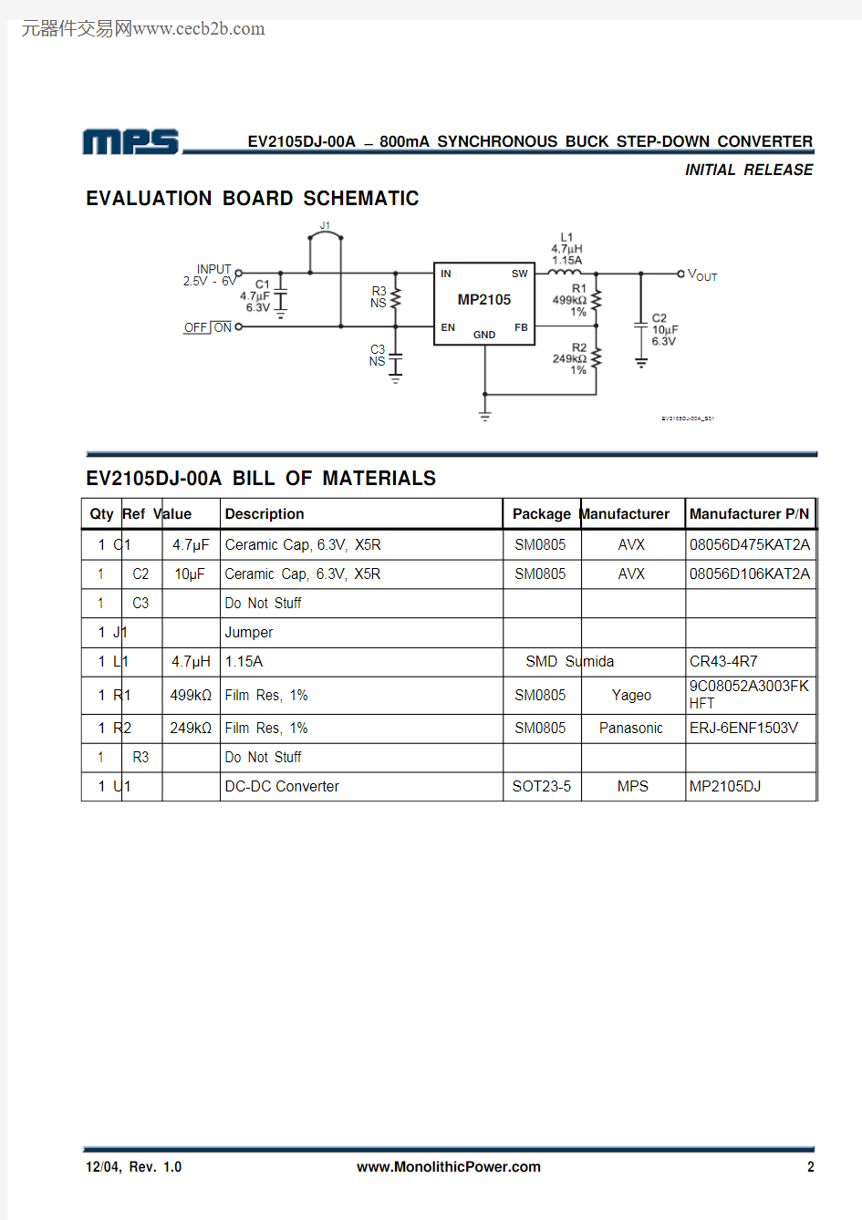
?High Efficiency: Up to 95%?800mA Available Load Current ? 2.5V to 6V Input Voltage Range ?Output Voltage as Low as 0.6V ?100% Duty Cycle in Dropout
?
Short Circuit Protection
?Thermal Fault Protection
?<0.1μA Shutdown Current
? Programmable Enable Control
APPLICATIONS
Cellular and Smart Phones
Microprocessors/DSP Core Supplies
PDAs
MP3 Players
Digital Still and Video Cameras
? Portable Instruments
, “MPS”, “Monolithic Power Systems”, and “The Future of Analog IC
Technology” are Registered Trademarks of Monolithic Power Systems, Inc. EV2105DJ-00A EVALUATION BOARD
Dimensions (2.0”X x 2.0”Y x 0.5”Z)
Board Number
MPS IC Number
EV2105DJ-00A MP2105DJ
E
F
F
I
C
I
E
N
C
Y
(
%
)
101001000
LOAD CURRENT (mA)
MP2105-EC01
Efficiency vs
Load Current
EV2105DJ-00A – 800mA SYNCHRONOUS BUCK STEP-DOWN CONVERTER
INITIAL RELEASE EVALUATION BOARD SCHEMATIC
V OUT
EV2105DJ-00A BILL OF MATERIALS
Qty Ref Value Description Package Manufacturer Manufacturer P/N 1 C1 4.7μF Ceramic
Cap,
6.3V, X5R SM0805 AVX 08056D475KAT2A 1 C2 10μF Ceramic Cap, 6.3V, X5R SM0805 AVX 08056D106KAT2A 1 C3 Do Not Stuff
1 J1 Jumper
1 L1 4.7μH 1.15A SMD Sumida
CR43-4R7
1 R1 499k?Film Res, 1% SM0805 Yageo 9C08052A3003FK HFT
1 R
2 249k?Film Res, 1% SM0805 Panasonic ERJ-6ENF1503V 1 R
3 Do Not Stuff
1 U1 DC-DC
Converter SOT23-5 MPS MP2105DJ
EV2105DJ-00A – 800mA SYNCHRONOUS BUCK STEP-DOWN CONVERTER
INITIAL RELEASE PRINTED CIRCUIT BOARD LAYOUT
Figure 1—Top Silk Layer Figure 2—Top Layer
Figure 3—Bottom Silk Layer Figure 4—Bottom Layer
EV2105DJ-00A – 800mA SYNCHRONOUS BUCK STEP-DOWN CONVERTER
INITIAL RELEASE
NOTICE: MPS believes the information in this document to be accurate and reliable. However, it is subject to change without notice. Contact MPS for current specifications. MPS encourages users of its products to ensure that third party Intellectual Property rights are not infringed upon when integrating MPS products into any application. MPS cannot assume any legal responsibility for any said applications.
EV2105DJ-00A Rev. 1.0 Monolithic Power Systems, Inc. 4
12/2/04 983 University Avenue, Building A, Los Gatos, CA 95032 USA QUICK START GUIDE
The output voltage of this board is set to 1.8V. The board layout accommodates most commonly used inductors and output capacitors.
1. Attach Positive end and Negative end of Load to VOUT and GND pins respectively.
2. Attach Input Voltage 2.5V ≤ V IN ≤ 6V and Input Ground to VIN and GND pins respectively.
3. To enable the MP2105 apply a voltage, 1.5V ≤ V EN ≤ 6V, to the EN pin. To disable the MP2105
apply a voltage, V EN < 0.3V, to the EN pin. The default setting for the jumper J1 on the board connects V IN to the EN pin. With this configuration, the part will operate without applying any external voltage to the EN pin. 4. The Output Voltage V OUT can be changed by varying R2. Calculate the new value by formula:
1V V 1R 2R FB
OUT ????
?????=
Where V FB = 0.6V and R1 = 499k ?. Example: For V OUT = 2.5V:
?=???
?????
=
k 1741V 6.0V 5.2k 4992R
Therefore, use a 174k ? standard 1% value.