Deposition of Ti–6Al–4V using a high power diode laser and wire Part I

Deposition of Ti –6Al –4V using a high power diode laser and wire,Part I:
Investigation on the process characteristics
Sui Him Mok,Guijun Bi ?,Janet Folkes,Ian Pashby
Innovative Manufacturing Processes Group,School of Mechanical,Materials and Manufacturing Engineering,
University of Nottingham,University Park,NG72RD,UK
Received 24September 2007;accepted in revised form 4February 2008
Available online 20February 2008
Abstract
In this paper the deposition of Ti –6Al –4V wire with High Power Diode Laser was investigated by producing single tracks.The effect of the wire feeding direction and angle was firstly studied.The influence of laser power,traverse speed and wire feed rate on the weight and dimension of the deposited single tracks was then investigated.The microstructure and hardness of the single tracks were examined.Deposition with diode laser and wire was proved to provide a high deposition rate with good quality.Columnar grains were found in the deposits.Wire feeding orientation,laser power,traverse speed and wire feed rate were verified as factors which influenced the quality of the deposit.With similar energy level,different power/traverse speed produced deposits with different hardness value.Hardness values tended to increase from the deposit,via the re-melted zone till to the heat affected zone,and then decrease again when the measurements were taken in the unaffected base material.?2008Elsevier B.V .All rights reserved.
P ACS:81.15.Fg
Keywords:Deposition;Diode laser;Ti6Al4V
1.Introduction
Direct metal deposition with laser has been verified as a promising process for surface modification,repair and compo-nent building [1,2].Recently,further studies have been carried out to explore the feasibility of applying this process in the aero-space industry [3–6].The surface cladding can be used to generate a thin functional layer on the surface of the component made by cost-effective material.The material of the clad layer is different from the base material,which can provide high tem-perature corrosion and wear resistance.For the application of the metal deposition process,a high deposition rate or volume is required.The components produced should also have the same properties and functions as ones made by conventional methods.In the development stage,traditionally,the components are made by stock removal method,forging or casting,such as,precision sand casting and investment casting.However,when
there is any modification on the design,the production time for the new components would be very long.The concept of the proposed application methodology is by using the traditional methods to produce a “basic ”structure and applying the direct metal deposition to add the feature onto it.So,it could help to save time for manufacturing the whole structure and have higher flexibility in modifying the design in a shorter period of time.Moreover,for the repair process,it can save time and costs compared with the replacement by a new component [7].
Due to its outstanding strength-to-weight ratio,Ti –6Al –4V is one of the main materials used in the aerospace industry [8].In the U.S.this alloy accounts for about half of all titanium alloy usage [9,10].Ti –6Al –4V plays a major role in the blades,disc and the cooler parts of the compressor in the jet engines because high strength and creep resistance are required in these applications [11,12].Nowadays,there is increasing use of Ti –6Al –4V for quite critical applications for the forged structural members in aircraft,including undercarriage components,flap and slat tracks in wings and for engine mountings [13].
Most of the researches have focused on the deposition with powder,which is difficult to achieve a comparable deposition
Available online at https://www.360docs.net/doc/f39999675.html,
Surface &Coatings Technology 202(2008)3933–
3939
https://www.360docs.net/doc/f39999675.html,/locate/surfcoat
?Corresponding author.
E-mail address:biguijun@https://www.360docs.net/doc/f39999675.html, (G.Bi).
0257-8972/$-see front matter ?2008Elsevier B.V .All rights reserved.doi:10.1016/j.surfcoat.2008.02.008
rate to the traditional processes,such as PTA and TIG processes.Therefore,the proposed methodology,direct diode laser depo-sition with wire would be a possible way to overcome limi-tations in surface cladding,manufacturing and repair.For this technology metal wires are used as the additive material.During the powder deposition process a certain amount of powders can not be caught by the melt pool.The powders are blown to the surrounding environment,which causes potential hazard to the operators and the https://www.360docs.net/doc/f39999675.html,pared with powder feeding,wire feeding method has higher material usage efficiency.Al-most all the materials fed into the melt pool during the process are used to form the deposit.It lowers the risks to the operators and makes the process environment friendly.Moreover,the powder feeding nozzle plays an important role in the powder deposition process.It makes the deposition with powder more complicated than with wire.Another merit is that metal wires are easily available and cheaper than powders,which makes the wire deposition very cost-competitive.
In the literature [14]the study on the deposition of stainless steel wire with diode laser was reported.Wire deposition with Nd:YAG laser was also investigated in the literatures [15,16].However,no detailed research has been carried out to study the influence of the wire orientation,laser power,traverse speed and wire feed rate on the deposit quality.Also the deposition of Ti-
alloy wire with diode laser is a promising research area.How-ever,most of the researches focused on the deposition with Ti-alloy powders [3–6,17,18].
The aim of this project is to get an insight into the process characteristics in an attempt to understand the property,struc-ture and process interaction associated with the direct diode laser deposition with wire feeding of Ti –6Al –4V.Deposit quality and deposition rate will also be investigated.Parameters will be optimised.The main properties of the deposit including the microstructure,micro-hardness will be investigated.2.Experimental procedure 2.1.Experimental setup
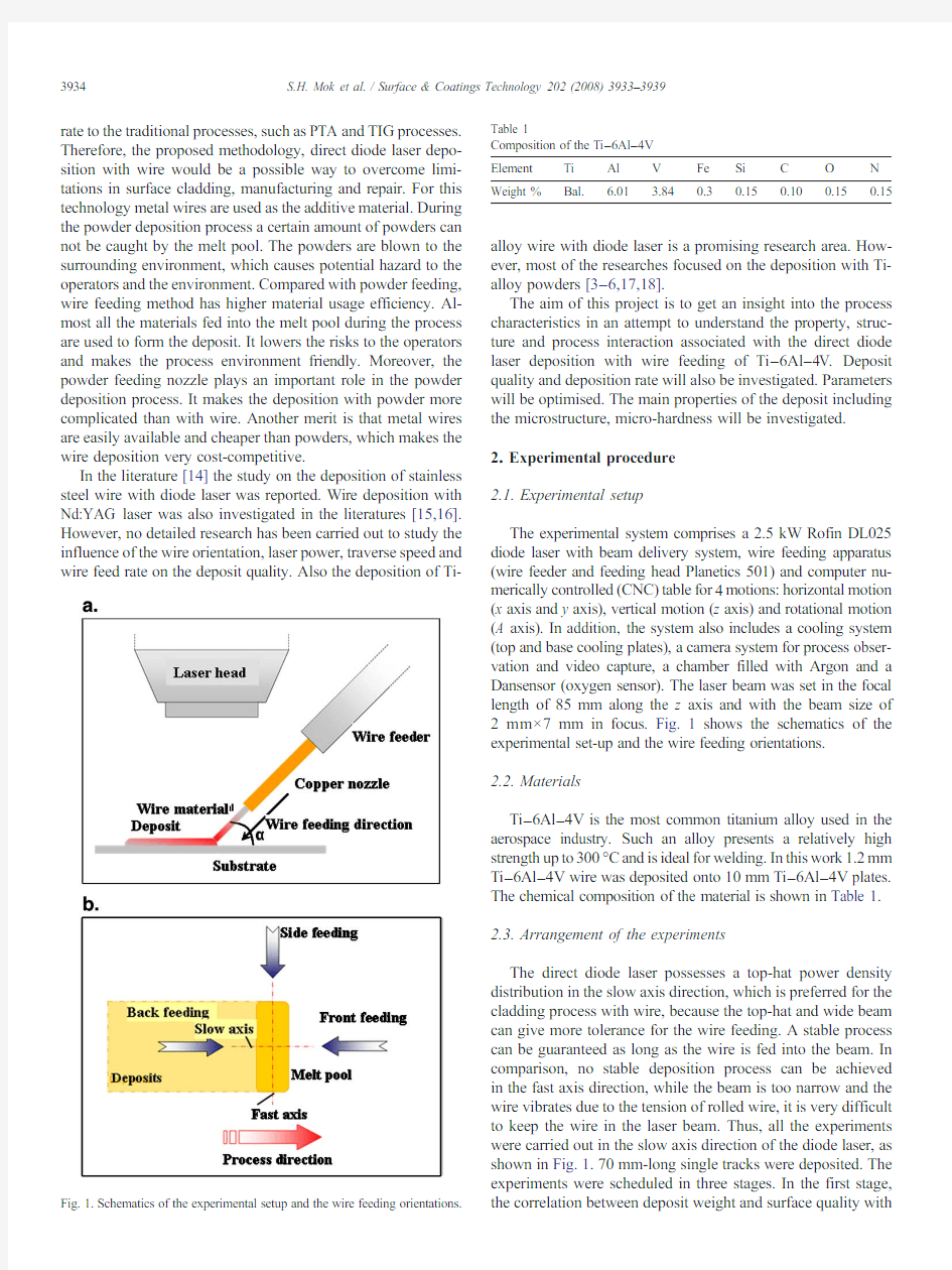
The experimental system comprises a 2.5kW Rofin DL025diode laser with beam delivery system,wire feeding apparatus (wire feeder and feeding head Planetics 501)and computer nu-merically controlled (CNC)table for 4motions:horizontal motion (x axis and y axis),vertical motion (z axis)and rotational motion (A axis).In addition,the system also includes a cooling system (top and base cooling plates),a camera system for process obser-vation and video capture,a chamber filled with Argon and a Dansensor (oxygen sensor).The laser beam was set in the focal length of 85mm along the z axis and with the beam size of 2mm×7mm in focus.Fig.1shows the schematics of the experimental set-up and the wire feeding orientations.2.2.Materials
Ti –6Al –4V is the most common titanium alloy used in the aerospace industry.Such an alloy presents a relatively high strength up to 300°C and is ideal for welding.In this work 1.2mm Ti –6Al –4V wire was deposited onto 10mm Ti –6Al –4V plates.The chemical composition of the material is shown in Table 1.2.3.Arrangement of the experiments
The direct diode laser possesses a top-hat power density distribution in the slow axis direction,which is preferred for the cladding process with wire,because the top-hat and wide beam can give more tolerance for the wire feeding.A stable process can be guaranteed as long as the wire is fed into the beam.In comparison,no stable deposition process can be achieved in the fast axis direction,while the beam is too narrow and the wire vibrates due to the tension of rolled wire,it is very difficult to keep the wire in the laser beam.Thus,all the experiments were carried out in the slow axis direction of the diode laser,as shown in Fig.1.70mm-long single tracks were deposited.The experiments were scheduled in three stages.In the first stage,the correlation between deposit weight and surface quality
with
Fig.1.Schematics of the experimental setup and the wire feeding orientations.
Table 1
Composition of the Ti –6Al –4V Element Ti Al V Fe Si C O N Weight %
Bal.
6.01
3.84
0.3
0.15
0.10
0.15
0.15
3934S.H.Mok et al./Surface &Coatings Technology 202(2008)3933–3939
various feeding orientations were presented.Conclusions were drawn and preferred wire feed angle and direction were defined for further experiments.In the second stage,the correlations of deposit weight with traverse speed and wire feed rate were presented and preliminary observations of the deposition pro-cess were made.Preferred wire feeding rates were defined for further experiments.In the third stage,further works were car-ried out on exploring the characteristics of the direct laser depo-sition process in terms of deposit dimension,microstructure and micro-hardness.
2.4.Characterization of the samples
The samples were cross-sectioned and polished to examine deposit quality with respect to dimension,porosity,and micro-hardness.The samples were then etched using 2%HF +5%HNO3in water for the purpose of micro-structure analyses.Optical Microscopes were used to study and analyse the micro-structure.Micro-hardness test machine M-400developed by LECO was used to examine the hardness values of the single track deposition.For the testing,a 500g load and 15second loading time were applied.3.Results and discussion
3.1.Determination of the wire feed orientation
Experiments were carried out by changing the wire feed angles (15°,45°,and 60°)and directions (front,side and back
feeding),as shown in Fig.1,under a fixed laser power (2.06kW)and wire feed rate (2m/min)at various traverse speeds (100,200,300and 400mm/min).The graphs in Fig.2show the weight of the deposit at different angles with the same feeding direction.The data indicated that under the front feeding condition,feeding at 45°gave the highest deposition weight (6g at 100mm/min).Furthermore,on back feeding and side feeding,results showed that feeding at 60°and 15°were preferred,respectively.They had the weights of deposition of 5.7g and 6.6g at 100mm/min.No positive results were found when back feeding at 15°because there was very small clearance between the fed wire and the deposit during the process.Therefore,the wire easily hit the solidified deposit and bent onto the protective glass of the laser head,as shown in Fig.3.
Generally,front feeding and side feeding provided smoother surface compared with the back feeding.During back feeding,wire was fed on top of deposit.Thus,the materials seemed to be pushed away from the deposit.Therefore,a wavy surface with bulbs on the side of the deposit was formed in back feeding specimens.This is concordant to the results showed in [14]for deposition with stainless steel wire.For front and side feeding,the wires were fed from the direction towards the deposits.Therefore,the wires were melted,formed the deposits and pushed towards the previous still-red-hot deposits.The flow characteristics of melt in the melt pool are better in these con-ditions.Due to the surface tension effect,a better surface could be formed.Side feeding can provide a smooth surface but with uneven edges due to the feeding direction,as shown in Fig.4.The uneven edges were formed by the wire which firstly reacted with the melt pool on one side and more material was deposited on that side.
For selecting a suitable feeding orientation,high deposi-tion rate was a crucial factor.However,consistent feeding was also significant,especially in net-shape component deposition when making real parts.Multiple feeding directions could occur during the same process.As shown from the results,feeding at 15°is not suitable because deposition did not occur with back feeding at this angle.Therefore,feeding at 45°or 60°is preferred.Directional-wise,front feeding was more preferred because a more consistent feeding was achieved at the three different angles,within about 4.5g to 6g in total weight.As a result,front feeding at 45°was chosen for the further
experiments.
Fig.3.Trial in back feed at 15°with 100mm/min traverse
speed.
Fig.2.Weight of the deposit at different angles grouped by the same feeding direction.
3935
S.H.Mok et al./Surface &Coatings Technology 202(2008)3933–3939
3.2.Determination of the wire feed rate
Laser power was set at 2.06kW,the wire feed rate was varied from 0.83mm/min to 3.33m/min and the traverse speed was varied from 50mm/min to 300mm/min.The weight of deposit against traverse speed was plotted,as shown in Fig.5.It decreased while increasing the traverse speed in all the wire feed settings.The weight difference between the different wire feed rate reduced from about 4g to less then 1g,while the traverse speed increased.Especially,while the traverse speed reached at 200mm/min,the weight of deposits was almost the same above wire feed rate of 2.22m/min.The humps observed for 2.22and 3.33m/min wire feed rates resulted from the unstable process caused by the too high wire feed rates.Some un-melted wire can be seen on the surface of the deposit.Furthermore,the relations between the weight of deposits and the wire feed rate at different traverse speed were plotted in Fig.6.The weight of the deposits increased while increasing the wire feed rates but trended to level off or decrease when it reached 2m/min.When the wire feed rate was set at high levels,wire could not be fully melted.Since there was no way for the wire to escape,it trended to push backwards into the wire feeder and the “cracking ”sounds were heard.There-fore,a preferred wire feed rate for the laser power 2.06kW and 1.65kW was chosen as 2m/min.Similarly,the preferred wire feed rate for the laser power 1.2kW was chosen as 1m/min.3.3.Effect of the laser power and traverse speed on the dimension of the deposit
Further experiments were carried out to investigate the in-fluence of the laser power and traverse speed on the dimen-sion of the deposit.A set of experiments with three different laser powers (2.06kW,1.65kW and 1.2kW),various traverse speeds (50mm/min to 250mm/min),fixed wire feed rates (1m/min and 2m/min)and front feeding at 45°were adopted.Deposits were generally clean and free of cracks and porosity as shown in Fig.7.Deposit materials were fully melted and metallurgically bound to the base plates.Dimensional analyses were carried out with the cross sectioned samples.Deposit height,width and deposit angle were measured according to the schematic in Fig.8.As can be observed in Fig.9,at the same setting of laser power and wire feed rate,both deposit height and deposit width decreased with increasing traverse speed,especially the deposit height.For the deposition with 2.06kW laser power and 2m/min wire feed rate,the deposit height decreased from 4.96mm to 1.40mm (decrease up to 72%)with increasing traverse speed.When the traverse speed was kept constant,such as at 50mm/min,the deposit height changed from 4.96mm to 3.13mm (a reduction of about 39%).These showed that the changes of traverse speed have a more sig-nificant effect on the deposit height than the laser power.The deposit width changed only from 7.92mm to 7.16mm (decrease less 10%)with increasing traverse speed.With the increasing laser power from 2060W to 1200W and a constant traverse speed,such as at 50mm/min,the deposit width de-creased from 7.92to 6.84mm (declines 13.6%).In the case of 150mm/min traverse speed,the deposit width varied from 7.27to 6.42mm (varies about 11.7%).Such results indicated that laser power affects deposit width more significantly than the traverse speed.The very low changes of deposit width resulted from the constant melt pool size created by the laser beam at the same power
level.
Fig.4.Photos of the surface and cross-section of the single track deposited by side
feeding.
Fig.5.Weight of the deposit against traverse
speed.Fig.6.Weight of the deposit against the wire feed rate.
3936S.H.Mok et al./Surface &Coatings Technology 202(2008)3933–3939
Deposit angle,also known as the contact angle (θc ),is one of the factors affecting the deposition quality,especially in surface deposition and structure build.In the laser deposition process,the contact angle is determined not only by the surface tension effect in the molten material,but also predominately by the laser beam size and spatial power density distribution.Acute angles are preferred in the direct diode laser deposition process.Therefore,good dense deposition could be achieved and no inter-run porosity would form.If the deposit angle is greater than 90o ,gaps in between overlapping tracks during the deposition would form [19].
Five cross-sections were prepared for each single track and the deposited angles were measured at both left and right sides.The average values were adopted for the discussion.As shown in Table 2,most of the deposit angles are acute angles,ranging from 31o to 68o except the two highlighted settings (laser power =2.06kW and 1.65kW with traverse speed =50mm/min).It suggested that most of the settings are suitable for the surface deposition and structure building.Furthermore,at the same wire feeding rate,the deposit angle shows significant
dependence on the ratio of laser power and traverse speed.The angle increases with increasing ratio.3.4.Micro-structure
Fig.10shows that all the deposits possess a columnar structure.The grains in the deposit grew directionally from the outer surface towards the centre of the melt pool.The cooling direction dictated the grain structure.Heat conduction through the base plate domi-nated the cooling effect compared with cooling via the deposit surface and the base plate through radiation and convection.The heat conduction in the deposit was slow,compared to the re-melted and Heat Affected Zone (HAZ).Therefore,large size columnar grains grew parallel to the cooling direction,as shown in Fig.10a,c and e.The grain size ranges from a few hundred microns to several millimeters depending on different laser power and traverse speed.On the other hand,the materials in the re-melted zone and HAZ were cooled down quickly by conduction.Fig.10b,d and f shows the microstructures of these two regions.The
grains
Fig.7.Cross-section of the single tracks deposited with different set of
parameters.
Fig.8.Schema of the cross-section for the dimension
measurement.Fig.9.Dimension of the single tracks deposited with different set of parameters.
3937
S.H.Mok et al./Surface &Coatings Technology 202(2008)3933–3939
in the re-melted area were larger in size(100to200μm)compared with the grains next to the bottom of HAZ(less than100μm).This indicates that the cooling in the bottom of HAZ is faster than that in the middle.
Comparing the grain sizes of the samples with different tra-verse speed and laser power–traverse speed:a and b versus c and d;laser power:a and b versus e and f,results indicate that these two process parameters affected the grains sizes of the deposits.The grain size of both deposits and HAZs decreased while increasing the traverse speed.With reduced laser power,grain size became smaller,especially the size in the deposit.However,the impact was not as significant as the influence of traverse speed.
3.5.Micro-hardness
By considering the influence of different laser power and traverse speed in terms of micro-hardness,Fig.11shows the micro-hardness tested with selected samples.As can be seen,the hardness declined gradually with the increase of the distance away from the interface.The hardness value decreased rapidly between310HV and350HV after entering a particular region. This region was in the base plate,which was not affected by the laser energy.
The fluctuation of the hardness in one track resulted from the different cooling rate in different regions.After the laser passed through,the re-melted area and the deposit layer started cooling down from a high temperature(over1000°C)to room tem-perature(around25°C)in a short period of time.The materials were subjected to a condition like quenching in heat treatment and small grains in size were formed.The heat generated by the laser in the re-melted area and HAZ region was dominantly transferred in all directions to the base plate by conduction.And the
heat
Fig.10.Microstructure of the selected
deposits.
Fig.11.Hardness of the selected single tracks.
Table2
Dependence of the deposit angle on the traverse speed and laser power
Laser power Traverse speed(mm/min)
Angle50100150200250
Power=2.06kW Left98°68°47°35°33°
Right92°62°46°36°31°
Power=1.65kW Left96°61°42°34°
Right88°60°48°38°
Power=1.2kW Left56°49°33°
Right60°51°36°
3938S.H.Mok et al./Surface&Coatings Technology202(2008)3933–3939
conduction is more effective in these two regions than in the deposited layer,which resulted in the finer grain size in the re-melted area and HAZ,as discussed in Section3.4.As a result a higher hardness in these two regions than in the deposited layer was observed.The difference of the three hardness curves can be explained by the different energy input and the resulted different size of the microstructure.Results show that the highest values of energy input(2.06kW and50mm/min)which mean the deposits and base materials absorbed the largest quantity of energy to heat up the materials.Therefore,obviously,the longest time is needed to cool down back to the room temperature and longer time for the grains to grow.As a result,the deposit possessed a larger grain size.The larger the grains size,the less the grain boundaries in the structure and the lower values of hardness resulted.
4.Conclusions
The characteristics of the deposition of Ti6Al4V wire with high power diode laser for the surface modification and component building was investigated.Based on the results showed above,the following conclusions can be drawn:
?Direct Diode Laser Deposition with wire provides a high deposition rate process:1kg/h of titanium can be achieved;
the deposition showed good dense,free of porosity,clean and smooth surfaces
?Front wire feeding with45°angle was verified as the best feeding orientation and a maximum wire feeding rate of2m/ min was achieved for the set-up in this research
?The results manifested that the deposition width is mainly determined by laser power;however,traverse speed influ-ences the height more significantly than laser power;the deposit angle achieved in this study is mainly acute,which is suitable for the modification of large surface and component building with overlapping deposition
?Epitaxial columnar grains in the deposit were found parallel to the building direction;The higher the energy acting on the process,the larger the grain size obtained ?For the same laser power,higher traverse speed setting resulted in a higher hardness value;for the same traverse speed,the lower laser power brought a higher hardness References
[1]K.Eimann,M.Drach,K.Wissenbach, A.Gasser,Proceedings of
Stuttgarter Lasertage,Sept.25-262003,Stuttgart,Germany.
[2]A.Gasser,K.Wissenbach,R.Poprawe,Laser Optoelektron.29(3)(1997)
66–75.
[3]I.Kelbassa,E.W.Kreutz,C.Over,L.Trippe,K.Wissenbach,Proceedings
of the2nd Pacific International Conference on Application of Lasers and Optics,PICALO2006,April3–52006,Melbourne,Australia.
[4]C.Bremer,3rd International Conference on Laser Assisted Net Shape
Engineering,LANE'2001,August28–312001,Erlangen,Germany.
[5]F.G.Arcella,F.H.Froes,JOM52(5)(2000)28–30.
[6]I.Kelbassar,E.W.Kreutz,P.Albus,L.Zhu,Proceedings of the24th
International Congress on Applications of Lasers&Electro-Optics:Laser Materials Processing Conference,Oct.312005–Nov.32005,p.660, Miami,USA.
[7]V.Malin,R.N.Johnson,F.M.Sciammarella,the AMPTIAC Quarterly8(3)
(2004)3–9.
[8]J.C.Ion,Laser Processing of Engineering Materials:Principles,Procedure
and Industrial Application,Elsevier,Oxford,2005.
[9]Titanium Alloys–Ti6Al4V Grade5,2003https://www.360docs.net/doc/f39999675.html,.
[10]I.J.Polmear,Light Alloys–Metallurgy of the Light Metals,Edward
Arnold(Publishers)Ltd.,1981.
[11]E.W.Collings,the Physical Metallurgy of Titanium Alloys,American
Society for Metals,1984.
[12]On-Line Materials Information Site,https://www.360docs.net/doc/f39999675.html,.
[13]Applications for Titanium alloys,International Titanium Association,2003
https://www.360docs.net/doc/f39999675.html,.
[14]W.U.H.Syed,L.Li,Appl.Surf.Sci.248(2005)518.
[15]J.D.Kim,Y.Peng,https://www.360docs.net/doc/f39999675.html,sers Eng.33(2000)299.
[16]M.L.Griffith,M.T.Ensz,D.L.Greene,D.E.Reckaway,J.A.Morin,T.E.
Bucheit,T.B.Crenshaw,https://www.360docs.net/doc/f39999675.html,van,V.Tikarae,J.A.Remero,Sandia report,Sandia National Laboratories,1999;
S.M.Kelley,S.L.Kampe,Metall.Mater.Trans.A-Phys.Metall.Mater.
Sci.35A(2004)1861.
[17]P.A.Kobryn,S.L.Semiatin,JOM,53(9)(2001)40.
[18]P.A.Kobryn,E.H.Moore,S.L.Semiatin,Scripta Mater.43(2000)299.
[19]W.M.Steen,Laser Material Processing,3rd edition,Springer-V erlag,
London,2005Limited.
3939
S.H.Mok et al./Surface&Coatings Technology202(2008)3933–3939
2017年钛及钛合金行业分析报告
2017年钛及钛合金行业分析报告 2017年10月
目录 一、行业管理体制和行业政策 (4) 1、行业管理体制 (4) 2、行业主要法律法规及政策 (4) 二、钛金属概况 (5) 三、行业上下游之间的关系 (6) 四、行业壁垒 (7) 1、技术壁垒 (7) 2、政策壁垒 (8) 3、资金壁垒 (9) 4、客户信任度壁垒 (9) 五、行业发展现状、趋势和规模 (10) 1、世界钛行业发展现状 (10) (1)优质钛矿 (10) (2)海绵钛 (11) (3)钛废料 (11) (4)中间合金 (12) 2、我国钛行业发展现状 (12) 3、我国钛及钛合金市场规模及市场供需 (14) (1)市场规模 (14) (2)进口情况 (15) (3)市场需求 (15) 4、我国钛行业发展趋势 (17) (1)钛产品技术创新 (17) (2)产品向高端领域转移 (17) (3)钛工业逐渐趋于国际化、规模化 (18) 六、行业风险特征 (18)
1、宏观经济影响引起的行业风险 (18) 2、高端钛的供应风险 (19) 3、中低端钛制品产能过剩,产业结构亟待调整 (19) 4、自主创新能力不强 (19) 5、环境保护的风险 (20) 七、影响行业发展的因素 (20) 1、有利因素 (20) (1)完整的钛产业链体系已经形成 (20) (2)国家不断推动技术创新 (21) (3)政策扶持 (21) 2、不利因素 (22) (1)高品位钛矿资源缺乏,同质化、中低端钛产品产能过剩 (22) (2)钛及钛合金产品的稳定性与国外还有很大的差距 (22) 八、行业竞争状况 (23)
反应注射成型技术在聚氨酯材料合成中的研究与应用
反应注射成型技术在聚氨酯材料合成中的研究与应用 摘要:主要介绍反应型注射技术,以及在聚氨酯合成中的研究与应用,并对几种不同的类型的RIM-PU注射成型技术进行介绍 关键词:反应型注射聚氨酯自增强 1. 前言: 反应注射成型,简称RIM( Reaction Injection Molding),是将两种或两种以上具有反应性的液体组分在一定温度下注入模具型腔内,在其中直接生成聚合物的成型技术。即将聚合与成型加工一体化,或者说,直接从单体得到制品的“ 一步法注射技术”。和传统的热塑性注射成型(TIM)不同,RIM是单体在模具中聚合而形成固体聚合物,而TIM是聚合物在模具中冷却才成型。其它反应成型加工方法,如单体浇铸成型、热固性塑料的注射成型,虽然也是在形成部件的形状后完成聚合反应。而在RIM中,单体和模具的温度没有很大的不同,而是靠基体激烈撞击混合来活化反应。和各种聚合物加工方法相比RIM制品最节能,RIM 是目前聚合物加工领域中引人注目的新方向。 RIM技术可用于聚氨酯、硅橡胶、环氧树脂和尼龙的成型加工。RIM聚氨酯发展尤为迅速,现已用于制造汽车内饰件、机器外壳和家具等。汽车行业为了获得高模量的聚氨酯制品,又发展了增强反应注射成型(RRIM)。聚氨酯(PU) 反应注射成型(RIM) 近年来发展十分迅速,其主要原料有A料和B料。A料通常为低分子量聚酯或聚醚,有时也加入其他添加剂。B料为各种异氰酸酯,目前国内外常用二苯甲烷二异氰酸酯(MDI )或液化改性MDI (L—MDI)。反应注射成型聚氨醋( RIM—PU) 是70年代初聚合物加工领域中研制开发的一门新型交叉成型技术,它是由低粘度高活性的异氰酸酯和多元醇经高压碰撞混合,通过化学、物理等变化而成型的。它具有成型温度和压力低、能耗少、材料性能优良等优点,近年来发展和应用极为迅速。 2. RIM在聚氨酯方面的发展 聚氨酯RIM聚氨酯制品(RIM—PUR) 是世界上开发最早且首先达到实用
注射成型工艺
1注射成型的原理、特点、应用 原理:将粒状或粉状的塑料从注射机的料斗送入配有加热装置的机筒中进行加热熔融塑化,使之成为粘流态的熔体,然后再注射机柱塞的压推作用下,以很高的流速通过机筒前端的喷嘴注入温度较低的闭合型腔中,经过一点时间的保压冷却定型后,开模分型即可从型腔中脱出具有一定形状和尺寸的塑料制件。 特点: 应用: 2注射成型的工艺过程 答:注射成型工艺过程包括成型前的准备,注射过程和塑件的后处理三部分。 (1)成型前的准备:原料外观的检查和工艺性能测定;原材料的染色及对料粉的造粒;对易吸湿的塑料进行充分的预热和干燥,防止产生斑纹、气泡和降解等缺陷;生产中需要改变产品、更换原料、调换颜色或发现塑料中有分解现象时的料筒清洗;对带有嵌件塑料制件的嵌加进行预热及对脱模困难的塑料制件选择脱模剂等。 (2)注射过程:加料、塑化、注射、冷却和脱模。注射过程又分为充模、保压、倒流、交口冻结后的冷却和脱模。 (3)塑件的后处理:退火处理、调湿处理。 3注射成型工艺参数:温度、压力、作用时间 温度控制包括料筒温度、喷嘴温度和模具温度。 料筒温度分布一般采用前高后低的原则,即料筒的加料口(后段)处温度最低,喷嘴处的温度最高。料筒后段温度应比中段、前段温度低5~10°C。对于吸湿性偏高的塑料,料筒后段温度偏高一些;对于螺杆式注射机,料筒前段温度略低于中段。螺杆式注射机料筒温度比柱塞式注射机料筒温度低10~20°C。 压力分为塑化压力和注射压力。 作用时间(只完成一次注射成型过程所需的时间)亦称成型周期。 4注射成型周期包括哪几部分? 答:注射成型周期包括(1)合模时间(2)注射时间(3)保压时间(4)模内冷却时间(5)其他时间(开模、脱模、喷涂脱模剂、安放嵌件的时间)。 合模时间是指注射之前模具闭合的时间,注射时间是指注射开始到充满模具型腔的时间,保压时间是制型腔充满后继续加压的时间,模内冷却时间是制塑件保压结束至开模以前所需要的时间,其他是是指开模,脱模,涂脱磨剂,安放嵌件的时间。 塑件的结构工艺性设计
钛及钛合金机械加工要求综述
钛及钛合金机械加工要求 一、钛及钛合金切削特点: 1、变形系数小:变形系数小于或接近于1,切削在前刀面上滑动摩擦的路程大大增大,加速刀具磨损。 2、切屑温度高:在相同的切削条件下,切削温度可比切削45号钢时高出一倍以上。 3、单位面积上的切削力大:容易造成崩刃,加大刀具磨损并影响零件的精度。 4、冷硬现象严重:降低零件的疲劳强度,加剧刀具磨损。 5、刀具磨损:在切削温度高和单位面积上切削力大的条件下,刀具很容易产生粘结磨损。 二、刀具选择 1、切削加工钛及钛合金应从降低切削温度和减少粘结两方面出发,选用红硬性好,抗弯强度高,导热性能好,与钛合金金亲和性差的刀具材料。 2、常选用YG类硬质合金刀具比较适合,常用的硬质合金刀具材料为:YG8、YG 3、YG6X、YG6A、813、643、YS2T和YD15等。 3、也可以选用金刚石和立方氮化硼作刀具。 三、加工设备要求 1、设署专用加工场地,确定专用加工钛及钛合金的机床。 2、工作区域辅设橡胶板或木地板,以免碰伤、擦伤钛材表面。
3、与钛及钛合金接触的所有工具、夹具、机床或其它装置必须洁净。 4、经清洗过的钛合金零件,要防止油脂或指印污染,否则以后可能造成盐(氯化钠的应力腐蚀。 5、禁止使用铅、铜、锡、镉及其合金,锌基合金制作的工具,夹具与钛,钛合金接触。 四、切削加工的要求 1、由于钛及钛合金的弹性模量小,工件在加工中的夹紧变形和受力变形大,会降低工件的加工精度,工件安装时夹紧力不宜过大,必要时可增加辅助支承。 2、切削液选用不含氯化物的切削液。 3、切削时,应大量浇注切削液,使钛及钛合金加工时充分得到冷却。 4、加工时,应防止切屑在机床上堆积。 5、刀具用钝后立即进行更换,或降低切削速度,加大进给量以加大切屑厚度。 6、加工时如一旦着火,应采用滑石粉,石灰石粉末,干砂等灭火器材进行扑灭,严禁使用四氯化碳,二氧化碳灭火器,也不能浇水。
第一讲:钛及钛合金金应用领域
钛及钛合金金基本知识 一.钛的应用 我们现在在这工作的每一个人对钛都有一个初步的认识,都知道钛是一种比重轻,耐腐蚀,耐热性好等许多优良性能,被誉为“未来金属”“二十一世纪金属”是具有发展前途的新型结构材料。它有类是铝材的金属色泽,大家也解了一些钛材的有关知识。咱们先从海绵钛谈起,我国的钛矿储量是世界已探明储量的64%左右,从矿石工业类型上看,我国钛资源主要是原生钒钛磁铁矿岩矿,其次是外生钛铁矿沙矿,第三是金红石岩矿,第四是金红石沙矿,我国钛精矿产能只要分布在四川攀枝花,海南,广西,攀枝花是我国最大的钛精矿供应基地,占中国市场的90%以上。钛资源主要用来生产钛白,金属钛(海绵钛),含钛钢以及钛焊丝和涂料。海绵钛主要是通过镁还原和钠还原(蒸馏法)二种方法,其它方法还没有工业化生产。2008年底,中国海绵钛产量达到6万吨,居世界第一。钛加工材2.7万吨左右,宝钛2008年钛加工材1.1万吨。钛锭生产约5万吨。宝钛只占1/5多。在中国化工用钛是第一大户,占全国用钛量的44%左右,航空航天占17%左右,体育休闲领域的用钛量为16%,排行第三。(据2007年统计)。在美国欧洲,钛材主要用于航空航天领域,约占60%,在日本,钛材主要用于化工.电力等领域,约占50%。而在中国,主要应用于化工.体有休闲等领域,约占70%。国外主要钛材生产企业有美国钛金属,Timet,RTI国际金属公司,Allegheny,日本的神户制铁.住友钛和新日铁。俄罗斯的VSMPO-AVISMA。 钛棒是怎样加工出来的,以前我们没有接触钛的时候,对钛都有一种神秘的感觉。的确,钛是一种新兴的金属,在20世纪如果说到钛,我们无论老少很多人会感到很陌生,不要说全国,就是咱们宝鸡号称是中国钛城,知道钛的人也不是很多。所以把钛称作稀有金属,曾经成立的中国稀有稀土集团中就有宝钛集团和遵义钛业的身影,其实钛元素在地球上并不是一个稀缺元素,在所有元素中排行老十,之所以把它排入稀有金属,主要是冶炼困难,工艺复杂,造成生产成本高,所以市场售价就高。钛材的价格大约是不锈钢的十倍,是普通钢的100倍左右。一般的地方是用不起的,到现在为止也只是用在航天航空军工化工医疗等用得起或者非用不可的地方。中国民用市场在70年代中期才大量推广应用。现在随着钛金属应用越来越广泛,以及钛的产能逐年大幅提高,知道和认识钛的人越来越多了。现在钛的应用除了国防工业的飞机,火箭,导弹,潜艇以外,化工,医学,体育,汽车,建筑,日常生活都有钛及钛合金的应用。而且今后钛的事业这块蛋糕会越做越大,发展越来越快,应用越来越广泛。钛是个朝阳产业。所以我们大家都应该对我们的企业未来充满信心。为什么今天先讲钛的应用,原因是我们每天都在钛行业里工作,就应该知道我们所生产的产品都用在哪些地方,不然,亲戚朋友问到你们钛是干什么的,都用在什么地方,答不上来会很尴尬的。销售部门的人知道了这些就知道到哪去找市场,质量部门的人知道了这些,就知道钛材料的标准为什么要这样要求。钛元素是英国分析化学家格列高尔在1789年在英国的默纳陈河谷中发现的,虽然他兴趣极浓,但是并没有引起人们的重视,直到二十世纪四五十年代才开始开发钛的应用,到现在也只有50多年的历史,最开始那是1954年美国人第一次炼出了钛合金,也就是Ti—6AI—4V, 钛的最早的应用是从航空工业开始的,后来在研制火箭.导弹.人造卫星.和航天器材时就考虑到钛的许多优点,也成为这些领域使用的重要材料之一。到现在也已经广泛的应用在
详细解析微注射成型技术以及其缺点
详细解析微注射成型技术以及其缺点 导语:微注射成型点击认领开放分类:技术微注射成型的提出源于1985年,微注射成型(也称微成型)用于生产总体尺寸、或特征功能区、或公差要求以毫米甚至微米计的制品。随着高技术和精密技术的快速发展,在光通信、计算机数据存储、医疗技术、生物技术、传感器和传动装置、微光学器件、电子和消费类产品,以及设备制造和机械工程等领域中,微注射成型制品呈现快速增长的需求。微注射成型- 简介微齿轮微注射成型的提出源于1985年,微注射成型(也称微成型)用于生产总体尺寸、或特征功能区、或公差要求以毫米甚至微米计的制品。随着高技术和精密技术的快速发展,在光通信、计算机数据存储、医疗技术、生物技术、传感器和传动装置、微光学器件、电子和消费类产品,以及设备制造和机械工程等领域中,微注射成型制品呈现快速增长的需求。典型例子包括:手表和照相机部件,汽车撞击、加速和距离传感器,硬盘和光盘驱动器读写头,医疗传感器,微型泵,小线轴,高精度齿轮、滑轮和螺旋管,光纤开关和接插件,微电机,外科仪器和通讯制品等。由于制品的微型特征,因此需要特殊的成型机械和辅助设备来完成各种生产操作,如:注射量控制、模具排空(真空)、注射工艺、制品顶出、分离、检验、存放、定位和包装。另外模具嵌件和模腔制造也需要特殊的技术。微注射成型- 分类尽管微注射成型的方法并没有清楚定义,但一般认为应用于生产以下三类产品或部件的工艺可称为微注射成型。1、重几微克到几分之一克,尺寸可能在微米(mm)级的微注塑成型制品,如微齿轮、微操纵杆等。图1是德国Hengstler公司用聚醚酰亚胺制得的微齿轮,齿轮轴孔直径和齿廓宽度均小于1mm。聚碳酸酯小透镜2、传统尺寸的注射成型制品,但具有微结构区域或特征功能区,例如:带有数据点隙的光盘、具有微表面特征的透镜、使用塑料薄片技术制造微齿轮的薄片等。图2和图3是聚碳酸酯小透镜和透明小齿轮。注意齿轮表面布有宽度小于1mm的同心圆,用于后续制作计数器的数据区。3、可具有任意尺度,但尺寸公差在微米级的高精度制品,例如光纤技术用接插件等。图4是一种汽车用微卡子,卡体采用聚甲醛(POM Delrin),卡体尾片厚度为700mm。为减轻运行时卡体振动,采用第二台注射机和旋转模具,在卡体中部共注射一小块弹性体,材料为PE-PA共聚物。微注射
注塑成型工艺条件调试规定
注塑成型工艺条件调试规定 1.0目的 制定本规定的目的,是对注塑工艺参数在设置、变更和记录、监督过程中可以标准化操作的部分进行规范,提高工艺参数的稳定性和再现性,减少注塑车间在换模、换料的生产切换过程中材料的损耗与工时的浪费,达到提高生产效率、稳定产品品质的目的。 2.0范围 适用注塑车间注塑机工艺参数的设置与管理 3.0职责 3.1调机员:正确的使用标准成型工艺,并对存在的问题及时向领班反馈,配合领班完成对异常情 况的处理。 3.2领班:正确的使用标准成型工艺,当因机器、模具、材料、运水等原因原标准成型工艺参数 不适用时,根据实际情况作出相应改变以保证生产的进行并配合在工艺改变后IPQC的品质确 认工作。并将工艺变更情况向主管汇报。 3.3主管:发布和认可标准成型工艺,确认工艺变更的正确性并完成相应记录。对不正确的工艺进 行修改并将原因告示领班和技术员,确保生产是在正常和经济的状态下进行。 4.0标准成型工艺参数的设置和调整的一般原理和注意事项 4.1设置成型参数的一般原理和注意事项。 4.1.1合模参数的设定。合模一般分为四段。 4.1.1.1慢速开始:为使机器平稳启动、合模应以慢速开始。 4.1.1.2快速到位:动模板在合模油缸推动下快速运动,以缩短工作周期。 4.1.1.3低压保护:油缸低压低速运动,以保护模具安全。对于三板模或有斜顶、铲机 结构的模具,动、定模接触时应适当降低速度和压力。 4.1.1.4高压合模:以所需的合模力锁紧模具。应选用最低而又不使成品产生毛边的合 模力,既能提高效率又能延长机器模具寿命。 4.1.2开模参数的设定。开模一般分为三段。 4.1.2.1慢速开模:为不使产品撕裂、变形,应以慢速开模开始。 4.1.2.2快速到位:模具一经打开,应转为快速开模到位,以缩短工作周期。但对于三 板模具、有斜顶滑块的模具,在动、定模分离时应适当设定速度和压力,减轻 对模具和机器的冲击和降低噪音。 4.1.2.3慢速终止:将到终点时,为防止惯性产生冲击,应由中速转为慢速终止。 4.1.3顶出和顶退参数的设置。要注意提高生产效率、保护模具和降低噪音。 4.1.3.1顶出应选用能使模具顶出机构正稳运动的最高速度。必须保证产品不能出现变 形、白化、撕裂等顶出动作导致的缺陷。 4.1.3.2顶退应选用能使顶出机构平稳复位的较低压力和较高速度。
纯钛及钛合金热加工性能全参数
纯钛热加工性能参数 1. 来料牌号及化学成分 注:合金牌号对应标准GB/T3620.1-2007 2.纯钛的物理性能 熔点1668±4℃ 密度ρ=4.5g/cm3 弹性模量E=1.17×10⁵MPa、G=0.44×10⁵Mpa(约为钢的54%)导热系数λ=19.3Wm-1K-1 热膨胀系数10.2×10⁻⁶/℃(室温-700℃) 泊松比υ=0.33
3.常温下力学性能 4. 加热规范 板坯在热轧前需要在加热炉中均匀加热, 为防止氧扩散,应限制加热温度和时间,因此,从成材率、表面质量考虑,该扩散层的厚度越薄越好,为此,热轧带卷加热温度的设定应在保证稳定轧制并可卷制成带的情况下,尽可能低。通常工业纯钛在加热炉内最好加热至800~920℃。 纯钛料轧制时的加热制度和终轧温度 5. 轧制过程控制 热轧分为粗轧和精轧。粗轧通常使用可逆式轧机,从厚板坯(80~300mm )的轧制到供精轧机轧制的板材厚度(25~40mm ),需经5~7个道次的轧制。纯钛的粗轧终轧温度为790℃。精轧工序在6~7台串列式轧机进行,可将25~40mm 的板坯连续加工成钛带材(厚3~6mm ),轧制速度可达
300~600m/min。 轧制过程温度控制参数为:钛板坯在加热炉中加热到800~920℃,在910℃出炉;粗轧终轧温度为790℃,连续热轧时钛坯温度控制在650~800℃范围,终轧温度为670℃;在470~490℃温度范围进行卷取。轧制后立即将钛带在输出辊道上用水冷或空冷的方法,以大于5~10℃/s的速度冷却,在低于500℃时卷取,以保证带卷材质均匀。 其它工艺要点有:严格控制初轧及连轧时各机架压下量和各机架上带材的温度;避免辊道对带材表面划伤;每轧3~4块清理一下辊道上的金属沾污;热轧带卷初始阶段,需要建立一个稳定的、大于4MPa/mm2的后张力,防止因带材卷乱或松卷引起划伤。 轧制温度对纯钛的单位压力的影响
硬质合金金相实验方法及实验结果
(一)硬质合金简介 用粉末冶金的方法(包括:球磨、混料、压制成型和烧结)值得的WC-Co或WC-TiC -Co 合金称为金属陶瓷硬质合金。简称为硬质合金。随着工业生产的飞跃发展,硬质合金制品的应用及研究也不断扩大和深入。 (二)性能和用途 金属陶瓷硬质合金是一种较硬的材料,在某种场合下可以代替金刚石材料。他的特点是具有高的熔点,高的硬度,高的耐磨性及比高速钢更高的热硬性;切削温度高至1000℃,而刀具的硬度尚未显著下降。因此在金属切削中,它的切削效率是一般钢制刀具无可比拟的。同时,硬质合金制品的使用寿命也比钢制品高的多。 钨钴类合金一般强度和冲击韧性较高,而钨钛钴合金的耐磨性、热硬性、和允许的切削速度则较高。 硬质合金主要用于制造切削刀具刀头;又用作各种模具、轧棍、矿山及石油钻探工具等。 (三)组织与缺陷 钨钴类合金:组织由过剩的WC和以钴为基(溶有WC)的粘结相组成。缺陷则有污垢、η相、裂纹、WC相聚集的粗大颗粒。 (四)技术要求 低倍组织 硬质合金的低倍组织应均匀一致。不允许有黑心、气孔、分层、裂纹及脏污等缺陷。 高倍组织。 主要观察硬质合金中各相的组成,以及晶粒的大小、分布情况等。允许有个别粗大的碳化钨相晶粒存在,但不允许有大量堆积或普遍晶粒长大现象。 (五)金相试样的制备和检验方法 1、试样的制备 硬质合金金相试样的制备方法与一般钢铁试样不同,现将我对硬质合金金相试样的制备方法介绍如下,以供参考。 (1)取样和磨制 由于硬质合金制品表面与中心的组织存在差异,所以一般取制品的折断面或者剖面作为金相试样的磨面,有些制品不能进行破坏和折断,则可取比较有代表性的表面,将其磨去一定深度后进行检查。(注:磨面最好进行倒角处理) 将选定的试样观察面在磨床上磨平(若选定的观察面已经是平的,可免去此步骤),然后准备好一块抛光布(此步骤并非抛光),将大号金刚石粉末用手指沾取适量均匀涂于抛光机的抛光布上半径大约5厘米左右的圆周上,启动抛光机,于抛光布上洒适量的水(防止试样发热和利于试样磨平),然后小心的将试样放到告诉旋转的抛光布上进行磨平,磨的时候用力要均匀,并随时观察,感觉有干涩感的时候要即时洒水。待磨面光亮如镜子一样的时候,说明试样磨面已经磨平,可以进行抛光。 (2)抛光 经研磨后的试样,用粒度更小的小号金刚石粉末进行抛光,抛光选用和研磨同样的抛光布,抛光布要清洗干净。用同样的方法将小号金刚石粉末均匀涂于抛光布上同样的地方(半径5cm的圆周上),抛光和研磨时候的方法是一样的。待研磨面非常光亮的时候,在金相显微镜上以100倍物镜进行观察,当看到浅黄色的平面且几乎没有划痕或者划痕非常浅的时候,说明抛光成功。若感觉划痕很明显,则说明抛光失败,则继续抛光知道看考上述抛光成
成型工艺流程及条件介绍
成型工艺流程及条件介绍第一節成型工艺 1.成型工艺参数类型 (1). 注塑参数 a.注射量 b.计量行程 c.余料量 d.防诞量 e.螺杆转速 f.塑化量 g.预塑背压 h.注射压力和保压压力 i.注射速度 (2)合模参数 a.合模力 b.合模速度
c.合模行程. d.开模力 e.开模速度 f.开模行程 g.顶出压力 h.顶出速度 i.顶出行程 2.温控参数 a.烘料温度 b.料向与喷嘴温度 c.模具温度 d.油温 3.成型周期 a.循环周期 b.冷却时间 c.注射时间
d.保压时间 e.塑化时间 f.顶出及停留时间 g.低压保护时间 成型工艺参数的设定须根据产品的不同设置. 第二节成型条件设定 按成型步骤:可分为开锁模,加热,射出,顶出四个过程. 开锁模条件: 快速段中速度 低压高压速度 锁模条件设定: 1锁模一般分: 快速→中速→低压→高压 2.快锁模一般按模具情况分,如果是平面二板模具,快速锁模段可用较快速度,甚至于用到特快,当用到一般快速时,速度设到55-75%,完全平面模可设定到
80-90%,如果用到特快就只能设定在45-55%,压力则可设定 于50-75%,位置段视产品的深浅(或长短)不同,一般是开模 宽度的1/3. 3.中速段,在快速段结束后即转换成中速,中速的位置一般 是到模板(包括三板模,二板模)合在一块为止,具体长度应 视模板板间隔,速度一般设置在30%-50%间,压力则是 20%-45%间. 4.低压设定,低速设定一般是在模板接触的一瞬间,具体位 置就设在机台显示屏显示的一瞬间的数字为准,这个数字一般是以这点为标准,,即于此点则起不了高压,高于此点则大,轻易起高压.设定的速度一般是15%-25%,视乎不同机种而定,压力一般设定于1-2%,有些机则可设于5-15%,也是视乎不同机种不同. 5.高压设定,按一般机台而言,高压位置机台在出厂时都已 作了设定,相对来讲,是不可以随便更改的,比如震雄机在 50P.速度相对低压略高,大约在30-35%左右,而压力则视乎 模具而定,可在55-85%中取,比如完全平面之新模,模具排气良好,甚至于设在55%即可,如果是滑块较多,原来生产时毛 边也较多,甚至于可设在90%还略显不足. 加热工艺条件设定
钛及钛合金牌号和化学成分汇总
《钛及钛合金牌号和化学成分》(2009/11/30 15:05) (引用地址:未提供) 目录:行业知识 浏览字体:大中小 《钛及钛合金牌号和化学成分》 目前,金属钛生产的工业方法是可劳尔法,产品为海绵钛。制取钛材传统的工艺是将海绵钛经熔铸成锭,再加工而成钛材。按此,从采矿到制成钛材的工艺过程的主要步骤为: 钛矿->采矿->选矿->太精矿->富集->富钛料->氯化->粗 TiCl4->精制->纯TiCl4->镁还原->海绵钛->熔铸->钛锭->加工->钛材或钛部件上述步骤中如果采矿得到的是金红石,则不必经过富集,可以直接进行氯化制取粗TiCI4。另外,熔铸作业应属冶金工艺,但有时也归入加工工艺。 上述工艺过程中的加工过程是指塑性加工和铸造而言。塑性加工方法又包括锻造、挤压、轧制、拉伸等。它可将钛锭加工成各种尺寸的饼材、环材、板材、管材、棒材、型材等制品,也可用铸造方法制成各种形状的零件、部件。
钛和钛合金塑性加工具有变形抗力大;常温塑性差、屈服极限和强度极限比值高、回弹大、对缺口敏感、变形过程易与模具粘结、加热时又易吸咐有害气体等特点,塑性加工较钢、铜困难。 故钛和钛合金的加工工艺必须考虑它们的这些特点。 钛采用塑性加工,加土尺寸不受限制,又能够大批量生产,但成材率低,加工过程中产生大量废屑残料。钛材生产的原则流程如图1—1。 针对钛塑性加工的上述缺点,近年来发展了钛的粉末冶金工艺。钛的粉末冶金流程与普通粉末冶金相同,只是烧结必须要在真空下进行。它适用乎生产大批量、小尺寸的零件,特别适用于生产复杂的零部件。这种方法几乎无须再经过加工处理,成材率高,既可充分利用钛废料作原料,又可以降低生产成本,但不能生产大尺寸的钛件。钛的粉末冶金工艺流程为:钛粉(或钛合金粉)->筛分->混合->压制成形->烧结->辅助加工->钛制品。
钛合金切削加工知识
首页>行业信息>行业信息> 合金磨削刀具-钛合金的切削加工 摘要:文件地点传真-上海500kV世博输变电工程设备采购招标混凝土机械设备-我国混凝土泵车的研发趋势器材行业企业-2008年是纺织机械发展预测除尘器粉尘气体-现代锅炉除尘设备简介控制器技术空调-我国将制定变频控制器标准终结市场混乱新产品功能水平-中联环卫机械公司五款新产品通过验收波兰装配 厂徐州-扩大欧洲市场份额徐工波兰装配厂落成叉车鸟巢开幕式-龙工叉车为奥运鸟巢极速“变装”出力(图)刀具加工刀片-Kennametal公司推出KB9640新刀具工程机械企业-工程机械租赁业发展前景广阔1.钛合金可分为哪几类?钛是同素异构体,熔点为1720℃,在低于882℃时呈密排六方晶格结构,称为α钛;在882℃以上呈体心立方品格结构,称为β钛。利用钛的上述两种结构的不同特点,添加适当的合金元素,使其相变温度及相分含量逐渐改变而得到不同组织的钛合金。室温下,合金,磨削,刀具,丝锥,切屑,砂轮,磨损,铰刀,硬质合金,温度, 1.钛合金可分为哪几类? 钛是同素异构体,熔点为1720℃,在低于882℃时呈密排六方晶格结构,称为α钛;在882℃以上呈体心立方品格结构,称为β钛。利用钛的上述两种结构的不同特点,添加适当的合金元素,使其相变温度及相分含量逐渐改变而得到不同组织的钛合金。室温下,钛合金有三种基体组织,钛合金也就分为以下三类: (1) α钛合金:它是α相固溶体组成的单相合金,不论是在一般温度下还是在较高的实际应用温度下,均是α相,组织稳定,耐磨性高于纯钛,抗氧化能力强。在500℃~600℃的温度下,仍保持其强度和抗蠕变性能,但不能进行热处理强化,室温强度不高。 (2) β钛合金:它是β相固溶体组成的单相合金,未热处理即具有较高的强度,淬火、时效后合金得到进一步强化,室温强度可达1372~1666 MPa;但热稳定性较差,不宜在高温下使用。 (3) α+β钛合金:它是双相合金,具有良好的综合性能,组织稳定性好,有良好的韧性、塑性和高温变形性能,能较好地进行热压力加工,能进行淬火、时效使合金强化。热处理后的强度约比退火状态提高50%~100%;高温强度高,可在400℃~500℃的温度下长期工作,其热稳定性次于α钛合金。 三种钛合金中最常用的是α钛合金和α+β钛合金;α钛合金的切削加工性最好,α+p钛合金次之,β钛合金最差。α钛合金代号为TA,β钛合金代号为TB,α+β钛合金代号为TC。 2.钛合金有哪些性能和用途? 钛是一种新型金属,钛的性能与所含碳、氮、氢、氧等杂质含量有关,最纯的碘化钛杂质含量不超过%,但其强度低、塑性高。%工业纯钛的性能为:密度ρ=cm3,熔点为1800℃,导热系数λ=,抗拉强度 σb=539MPa,伸长率δ=25%,断面收缩率ψ=25%,弹性模量E=×105MPa,硬度HB195。 (1)比强度高:钛合金的密度一般在cm3左右,仅为钢的60%,纯钛的强度接近普通钢的强度,一些高强度钛合金超过了许多合金结构钢的强度。因此钛合金的比强度(强度/密度)远大于其他金属结构材料,见表7-1,可制出单位强度高、刚性好、质轻的零、部件。目前飞机的发动机构件、骨架、蒙皮、紧固件及起落架等都使用钛合金。 (2)热强度高:对于α钛合金,在350℃时TA6的巩达422MPa、TA7的σb达491MPa,在500℃时TA8的σb达687MPa;对于α+β钛合金,在400℃时TC4的σb达618MPa、TC10的σb达834 MPa,在450℃时TC6和TC7的σb均达589MPa、TC8的σb达706MPa,在500℃时TC9的σb达785MPa。这两类钛合金在150℃~500℃范围内仍有很高的比强度,而铝合金在150℃时比强度明显下降。钛合金的工作温度可达500℃,铝合金则在200℃以下。
简析中国钛合金产业链及主要企业
中国钛合金产业链及主要企业分析 钛是一种常见金属,在地壳中的含量排在第九位,是铜的61倍。其中,钛及钛合金具有密度小、比强度高等特性,在减轻结构重量、提高结构效率、改善结构可靠性、提高机体寿命、满足高温及腐蚀环境等方面具有其他金属不可替代的作用,广泛用于材料化工、水利电力、航空航天、冶金钢铁等多个领域。钛产业因其优异的特性,成为《中国制造2025》和新材料产业发展指南中的重点。 钛合金产业链 我国是世界钛资源储量大国,已经初步建立了完整的钛产业体系。根据统计涉及显示,我国的钛材年产量约5万吨,总销量约为万吨,其中内销万吨。在我国,钛加工材主要被用于化工领域,其次为航空航天、电力等。近年来,我国的钛加工产业随下游需求高端化呈现结构升级,以航空航天为代表的高端钛材应用占比逐年提升。 钛合金的应用 钛正式成为工业性金属始于20世纪50年代,以1948年美国杜邦公叶成吨生产海绵钛(钛合金前级产品)为标准,其应用首先自军工和航空工业开始,后期逐步延伸至石油化工、能源工业等其他领域。 数据来源:中商产业研究院整理 钛合金相关企业 我国钛加工产业整体呈现低端产能过剩、高端产能不足的局面。在我国的“钛谷”宝鸡,存在着大小共计400家钛合金材加工厂商,其中,宝钛股份、西部材料和西部超导三家公司合计钛材加工年产能接近4万吨,足够支撑未来国内高端钛材市场需求。 三家公司钛材产品产能情况 数据来源:中商产业研究院整理 1、宝钛股份 是我国钛行业的龙头企业,目前钛材产能全国第一,也是目前国内唯一具有铸-锻-钛材加工完整产业链的龙头企业。公司产品广泛涵盖钛板材、管材、棒材、丝材,客户广布航空、航天、船舶、化工等多个领域。 2、西部材料 是我国规模较大、品种齐全的稀有金属材料深加工生产基地。目前形成了以钛产业(含钛及钛合金加工、层状金属复合材料、稀有金属装备及管道管件制造等)为主业,
反应注射成型技术
反应注射成型技术 反应注射成型起源于聚氨酯塑料。随着工艺技术的进步,该工艺也扩展到了多种材料的加工中。与此同时,为了拓宽 RIM 技术的应用领域,特别是在汽车行业中的应用,该工艺还引入了纤维增强技术。 RIM 简介 反应注射成型(简称“ RIM”是指将具有高化学活性、相对分子质量低的双组分材料经撞击混合后,在常温低压下注入密闭的模具内,完成聚合、交联和固化等化学反应并形成制品的工艺过程。这种将聚合反应与注射成型相结合的新工艺,具有物料混合效率高、流动性好、原料配制灵活、生产周期短及成本低的特点,适用于大型厚壁制品生产,故而受到了世界各国的重视。 RIM 最早仅用于聚氨酯材料,随着工艺技术的进步, RIM 也可应用于多种材料(如环氧、尼龙、聚脲及聚环戊二烯等)的加工。用于橡胶与金属成型的RIM 工艺是当前研究的热点。 为了拓宽 RIM 的应用领域,提高 RIM 制品的刚性与强度,使之成为结构制品, RIM 技术得到了进一步的发展,出现了专门用于增强型制品成型的增强反应注射成型( RRIM)和专门 用于结构制件成型的结构反应注射成型(SRIM)技术等。RRIM和SRIM成型工艺原理与 RIM 相同,不同之处主要在于纤维增强复合材料制品的制备。目前,典型的RIM 制品有汽车保 险杠、挡泥板、车体板、卡车货箱、卡车中门和后门组件等大型制品。它们的产品质量比 SMC产品好,生产速度更快,所需二次加工量更小。 RIM 成型工艺 1.工艺过程 RIM 工艺过程为:单体或预聚物以液体状态经计量泵以一定的配比进入混合头进行混合。混合物注入模具后,在模具内快速反应并交联固化,脱模后即为RIM 制品。这一过程可简化为:贮存T计量T混合T充模T固化T顶出T后处理。 2.工艺控制 (1)贮存。 RIM 工艺所用的两组分原液通常在一定温度下分别贮存在 2 个贮存器中,贮存器一般为压力容器。在不成型时,原液通常在 0.2~0.3 MPa 的低压下,在贮存器、换热器和混合头中不停地循环。对聚氨酯而言,原液温度一般为20~40 C,温度控制精度为土 1C。 (2)计量。两组分原液的计量一般由液压系统来完成,液压系统由泵、阀及辅件(控制液体物料的管路系统与控制分配缸工作的油路系统) 所组成。注射时还需经过高低压转换装置将压力转换为注射所需的压力。原液用液压定量泵进行计量输出,要求计量精度至少为± 1.5%,最好控制在± 1 %。 (3)混合。在 RIM 制品成型中,产品质量的好坏很大程度上取决于混合头的混合质量,生产 能力则完全取决于混合头的混合质量。一般采用的压力为10.34~20.68MPa,在此压力范围 内能获得较佳的混合效果。 (4)充模。反应注射物料充模的特点是料流的速度很高。为此,要求原液的粘度不能过高, 例如,聚氨酯混合料充模时的粘度为O.IPa.s左右。 当物料体系及模具确定之后。重要的工艺参数只有 2个,即充模时间和原料温度。聚氨酯物料的初始温度不得超过 90C,型腔内的平均流速一般不应超过0.5m/s。 (5)固化。聚氨酯双组分混合料在注入模腔后具有很高的反应性,可在很短的时间内完成固
注塑成型工艺流程及工艺参数
创作编号: GB8878185555334563BT9125XW 创作者:凤呜大王* 注塑成型工艺流程及工艺参数 塑件的注塑成型工艺过程主要包括填充——保压——冷却——脱模等4个阶段,这4个阶段直接决定着制品的成型质量,而且这4个阶段是一个完整的连续过程。 1、填充阶段 填充是整个注塑循环过程中的第一步,时间从模具闭合开始注塑算起,到模具型腔填充到大约95%为止。理论上,填充时间越短,成型效率越高,但是实际中,成型时间或者注塑速度要受到很多条件的制约。 高速填充。如图1-2所示,高速填充时剪切率较高,塑料由于剪切变稀的作用而存在粘度下降的情形,使整体流动阻力降低;局部的粘滞加热影响也会使固化层厚度变薄。因此在流动控制阶段,填充行为往往取决于待填充的体积大小。即在流动控制阶段,由于高速填充,熔体的剪切变稀效果往往很大,而薄壁的冷却作用并不明显,于是速率的效用占了上风。λ 低速填充。如图1-3所示,热传导控制低速填充时,剪切率较低,局部粘度较高,流动阻力较大。由于热塑料补充速率较慢,流动较为缓慢,使热传导效应较为明显,热量迅速为冷模壁带走。加上较少量的粘滞加热现象,固化层厚度较厚,又进一步增加壁部较薄处的流动阻力。λ 由于喷泉流动的原因,在流动波前面的塑料高分子链排向几乎平行流动波前。因此两股塑料熔胶在交汇时,接触面的高分子链互相平行;加上两股熔胶性质各异(在模腔中滞留时间不同,温度、压力也不同),造成熔胶交汇区域在微观上结构强度较差。在光线下将零件摆放适当的角度用肉眼观察,可以发现有明显的接合线产生,这就是熔接痕的形成机理。熔接痕不仅影响塑件外观,同时由于微观结构的松散,易造成应力集中,从而使得该部分的强度降低而发生断裂。 一般而言,在高温区产生熔接的熔接痕强度较佳,因为高温情形下,高分子链活动性较佳,可以互相穿透缠绕,此外高温度区域两股熔体的温度较为接近,熔体的热性质几乎相同,增加了熔接区域的强度;反之在低温区域,熔接强度较差。 2、保压阶段 保压阶段的作用是持续施加压力,压实熔体,增加塑料密度(增密),以补偿塑料的收缩行为。在保压过程中,由于模腔中已经填满塑料,背压较高。在保压压实过程中,注塑机螺杆仅能慢慢地向前作微小移动,塑料的流动速度也较为缓慢,这时的流动称作保压流动。由于在保压阶段,塑料受模壁冷却固化加快,熔体粘度增加也很快,因此模具型腔内的阻力很大。在保压的后期,材料密度持续增大,塑件也逐渐成
我国钛及钛合金板材未来发展趋势
我国钛及钛合金板材未来发展趋势 智研数据研究中心网讯: 内容提要:随着我国石油、化工等行业对设备的要求越来越高,以及制造业整体水平的快速提升,加之国内需求拉动与国际产业转移的“双重动力”带动下,我国钛材制造业从中长期市场上看,将继续保持快速稳定增长的良好势头。钛板带材作为钛材的重要支柱,产量将会进一步扩大。生产企业要紧抓这一机遇,并逐渐向新产品新业务转移,获得更大的发展空间。 内容选自智研数据研究中心发布的《2012-2016年中国钛行业运营态势及投资前景分析报告》 近年来,我国钛材的需求量迅速增加,已成为继美国和欧洲之后的第三大钛产品消费国。另据相关统计数据分析目前整个钛及钛合金板带材市场应用情况,最大用户是石油化工领域,约占钛板带材消耗总量的60%,其他依次为航空航天领域,约占15%,体育用品行业占6%,海水淡化、核电领域占5%,舰船及海洋工程装备领域占5%,其它领域约占9%。 2007 年我国钛加工材产量为23 640 t,其中钛板材产量为10 552 t,占44. 6%;2008 年我国钛加工材产量为27 737 t,其中钛板材产量为14 707 t,占53%,比上年产量上升了39. 4%;2009 年我国钛加工材产量为24 965 t,其中板材产量为12 067 t; 保守估计2010 年我国钛加工材生产量将达到30 000 t,其中板材产量为16 000 t,板材产量的增长率远高于整个钛加工材的产量增长率。今后,国内各应用领域对钛材需求仍将持续快速增加,继续保持两位数增长态势。 我国的大飞机计划、嫦娥登月计划、太空站计划、核电发展计划以及国家“十二五”发展规划对新型能源开发、高端装备制造业扶持与鼓励,这些为钛板带材提供了前所未有的发展空间和历史契机,同时又对钛板带材提出了更高的要求。 具体表现在: ①在品种方面,对钛带及焊管用薄钛板带需求增大; ②在规格方面,对于宽幅厚钛板( 宽2 000 ~2 500 mm,厚4 ~10 mm) 、宽幅薄钛板( 宽 1 000 ~1 500 mm,厚0. 4 ~3. 5 mm) 及10 ~70 mm 厚的宽幅( 2 400 mm 以上) 厚钛板材的需求日趋增长,而目前我国大部分的钛板生产企业,其装备能力无法满足这些超大、超厚规格的要求,因此未来的两年内,宽幅、超厚钛板材的市场前景良好; ③在化学成分方面,要求均匀化,且铁、氧等杂质含量控制范围窄幅化; ④表面光洁,组织细小均匀,力学性能优异,可满足航空航天、石油化工和核电等行业的苛刻要求。
尼龙 注塑成型工艺
华侨大学 课程名称:增强增韧尼龙66汽车专用料姓名:彭儒 学号:9 专业:08高分子二班 任课教师:钱浩
前言: 尼龙是结晶型塑料,品种颇多,已达到130多种,应用于注塑加工的有尼龙6、尼龙66、尼龙610、尼龙1010以及共聚性尼龙、超韧性尼龙、玻璃纤维增强尼龙、矿物增强尼龙等等。世界市场中,应用量最大的是尼龙66。 尼龙最早在1889年首先由Gabriel和Maass 两人合成制得,但系统的研究并最终实现工业化实在1929年,由美国杜邦公司的Carothers着手进行的。1931年Carothers申请了第一篇尼龙专利,1935年首先制得尼龙66,1939年实现工业化。 尼龙66的应用领域一般在汽车、电子电器、化工设备、机械设备等方面。从最终用途看,汽车行业消耗的尼龙66占第一位,电子电器占第二位。大约有88%的尼龙66通过注射成型加工成各种制件,约12%的尼龙66则通过挤出、吹塑等成型加工成相应的制品。 由于尼龙66优良的耐热性、耐化学药品性、强度和加工方便等,因而在汽车工业得到了大量应用,目前几乎已能用于汽车的所有部位,如发动机部位,电器部位和车体部位。发动机部位包括进气系统和燃油系统,如发动机气缸盖罩、节气门、空气滤清器机器外壳,车用空气喇叭、车用空调软管、冷却风扇及其外壳、进水管、刹车油罐及灌盖,等等。车体部位零部件有:汽车挡泥板、后视镜架、保险杠、仪表盘、行李架、车门手柄、雨刷支架、安全带扣搭、车内各种装饰件等等。车内电器方面如电控门窗、连接器、保鲜盒、电缆扎线等。 工艺特点:
⑴吸水性尼龙66较易吸湿,如果长时间暴露在空气下,会吸收大气中的水分。吸水后会发生体积膨胀,影响制品的尺寸精度,如在注塑前吸收过量的水分时,其制作的外国外观和力学性质都会受损。 ⑵结晶性尼龙66为结晶性高聚物,一般在20%~30%之间。结晶度的高低与性能有关,结晶度高,拉伸强度、耐磨性、硬度、润滑性等性能有所提高,热膨胀系数和吸水性趋于下降。 ⑶热稳定性在熔点以上温度,约254℃,水分子会与尼龙66发生化学反应,使聚合物水解或裂解,使尼龙66变色,树脂分子量及其韧性相对减弱,流动性增大,不单带来加工上的困难,而且会对制品性能造成损害。注塑时喷嘴流涎,制件飞边严重。聚合物裂解产生的气体和从空气中吸收的水分,共同夹击制件,轻则在表面形成不光洁、银丝、斑纹、微孔、气泡,重则反生熔体膨胀无法成型或成型后机械强度下降。最后,经过这种水解裂解的尼龙,其性能完全不可还原,即使重新干燥也不能再次使用。 干燥好的原料如果随便在空气中露置,会迅速在空气中吸收水分而使干燥效果丧失殆尽。即使在加盖的机台料斗内,存放的时间也不宜太长,一般雨天不超过1h,晴天限制在3h之内。 尼龙66熔融温度虽然高,但当达到熔点后,其粘度远较一般热塑性塑料如聚苯乙烯等低很多,故成型时流动性不成问题,尼龙66的流变特性是剪切速率增加时其表观粘度下降不突出,加之熔融温度范围较窄,在3~5℃之间,所以高的料温无疑是顺利冲模的保证,而不在乎高的注射速度和压力。 ⑷流动性尼龙66熔体的粘度低,流动性大,容易冲模成型,对薄壁制品更是如此,而且制品在模内能迅速固化,模塑周期短。
钛及钛合金锻造生产工艺规程汇总
更改控制页
本工艺规程适用于真空熔炼的钛及钛合金铸锭经加热、锻造、机加工等工序而制成棒坯、棒材、板坯、饼环材的生产,制定了每个生产工序的工艺制度和管理要求。 1简明工艺流程见表1。 2铸锭的准备 2.1生产工艺员在接到生产作业计划后,要仔细对计划部分内容进行审核,如有问题,及时和计划员沟通,确定无误后,方可编制生产工艺。并通知相关人员到库房领料。 2.2领料人员应根据GB/3620.1 钛及钛合金牌号和化学成分及化学成分允许偏差GB/3620.2及企标的有关规定,核对铸锭合格证,并核对合金牌号、锭号、规格和重量是否与实物相符,确认无误后,再进行转料。 2.3 铸锭转入锻造厂房应摆放整齐,将标识摆放于易看到的方位或用金属(记号笔)在铸锭的两端或表面将锭号明显标出。 2.4生产工艺员在投料前应仔细研究产品所执行的技术标准,保证其化学成份能满足该产品的技术要求。否则,不能投料。 2.5铸锭转入锻造车间后炉工在装炉前必须对铸锭进行涂层,涂层时将铸锭用垫木或导辊垫起,并将铸锭表面的杂脏物、油污用清洗剂擦洗干净后再涂防氧化涂层。 2.6涂层时将写锭号的地方不要涂,以便装炉前确认锭号是否正确。 2.7涂层的厚度应控制在0.2~0.4㎜。涂层后必须干透即24小时后方可装炉
铸锭 ↓ 涂层 ↓ 加热 ↓ 锻造 ↓ ↓↓↓ 打磨刨面打磨 ↓↓↓ 加热修磨加热↓↓↓ 锻造检查锻造↓↓↓ 热处理称重刻口↓↓↓ 机加板坯锯切↓↓ 探伤平头倒角↓↓ 取样 ↓↓ 检查 ↓↓ 修磨 ↓↓ 检查热处理↓↓ 称重机加↓↓ 包装探伤↓↓ 棒材取样 ↓ 检查 ↓ 称重 ↓ 包装 ↓ 饼环材