EUS20-120-NHBRVC中文资料

Features:
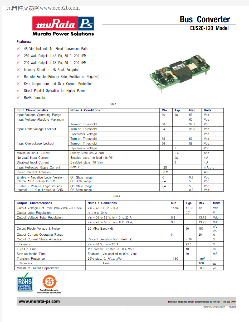
9 48 Vin, Isolated, 4:1 Fixed Conversion Ratio 9 250 Watt Output at 48 Vin, 55 C, 200 LFM 9 200 Watt Output at 38 Vin, 55 C, 200 LFM 9 Industry Standard 1/8 Brick Footprint
9 Remote Enable (Primary Side, Positive or Negative) 9 Over-temperature and Over Current Protection 9 Direct Parallel Operation for Higher Power 9 RoHS Compliant
Table 1
Input Characteristics
Notes & Conditions Min Typ. Max Units Input Voltage Operating Range 36 48 55 Vdc Input Voltage Absolute Maximum
60 Vdc Turn-on Threshold 36 37.5 Vdc Turn-off Threshold 34 35.5 Vdc Input Undervoltage Lockout
Hysteresis Voltage 2 Vdc Turn-on Threshold 55 57 Vdc Turn-off Threshold 56 58 Vdc Input Overvoltage Lockout Hysteresis Voltage
2 Vdc Maximum Input Current Steady-State (26 A out)
6.4 Adc No-Load Input Current Enabled state, no load (48 Vin) 98 mA Disabled Input Current
Disabled state (48 Vin) 6 mA
Input Reflected Ripple Current Note (10) 25 mA p-p Inrush Current Transient
0.2 A 2s Enable – Negative Logic Version Internal 10 K pull-up to 5 V. On State range Off State range -0.1 2.4 0.8 5.0 Vdc Vdc Enable – Positive Logic Version Internal 100 K pull-down to GND.
On State range Off State range
2.4 -0.1
5.0 0.8
Vdc Vdc
Table 2 Output Characteristics
Notes & Conditions
Min Typ. Max Units
Output Voltage Set Point (Vo=Vin/4 +0/-0.5%) Vin = 48.0 V, Io = 0 A 11.94 11.98 12.0 Vdc Output Load Regulation
Io = 0 to 20 A
0.7
V Output Voltage Total Regulation Vin = 36 to 55 V, Io = 0 to 20 A, 8.3 13.75 Vdc
Vin = 42 to 53 V, Io = 0 to 23 A,
9.7
13.25
Vdc Output Ripple Voltage & Noise 20 MHz Bandwidth 90 150
mV
p-p
Output Current Operating Range 0 20 A Output Current Share Accuracy Percent deviation from ideal (9) < 10 % Efficiency Vin = 48 V, Io = 20 A 95.5 % Turn-On Time Vin present: Enable to 90% Vout 10 mS Start-up Inhibit Time Enabled: Vin applied to 90% Vout 80 mS Transient Response 25% step, 0.1A/μs, ΔVo
160 mV Recovery Time 100 μs Maximum Output Capacitance 2000 μF
Bus Converter
EUS20-120 Model
Table 1
Protection Characteristics Notes & Conditions 0 Min Typ. Max Units
Output
Over-Current
Shutdown Non-Latching 24 25 27 A
Re-start
rate
75
msec Over Temperature Shutdown (5) Non-Latching 125 130 °C
Over Temperature Restart Hysteresis 10 °C
Table 2
General Specifications Notes & Conditions 0 Min Typ. Max Units
Isolation Voltage Input to Output 2250 Vdc
Isolation Resistance Input to Output 10 Mohm
Storage Temperature Range Non-condensing -40 125 °C
Operating Temperature Range Ambient (7) -40 100 °C
Thermal Measurement Location Temperature (7) See mechanical drawing for location 120 °C
Material
Flammability UL
94V-0
MTBF Calculated (Bellcore TR-332) 2.7 x10⁶ Hrs
Demonstrated 2 x10⁶ Hrs
Dimension 2.28”L x 0.9”W x 0.48”H (max)
(57.9L x 22.9W x 12.19H mm max)
Weight 30
grams Table 3
Standards Compliance Notes & Conditions (6)
UL/CSA 60950 Basic Insulation
EN60950 Certified
by
TUV
Notes:
Vin = 48Vdc, Ta = 25 °C, Airflow = 200 LFM for all data unless otherwise noted.
Output ripple voltage and noise is specified when measured with a 10uF tantalum and a 1uF ceramic capacitor at the converter output pins. Transient response is specified without a capacitor at the output of the converter.
Product operates with an external capacitance significantly greater than specified. However, for values higher than 2000uF please contact
C&D representative.
Thermal shutdown is monitored at the Thermal Measurement Location (TML). See ‘Mechanical Information’ on page 3 for TML location.
See ‘Safety Considerations’ shown on last page.
De-rating curves are conducted in a controlled environment. End application testing is required to ensure the Thermal Measurement
Location temperature is below the maximum specified.
Recommended airflow direction is from pin 1 to pin 3, or 3 to 1 (transverse airflow).
Current share accuracy is optimized when the source and load impedance presented to each converter is equal.
Input Reflected Ripple is specified when measured with a 12uH source inductance.
Mechanical Information
Figure 1
Pin Assignment
Table 4
Pin # Pin Name Function Notes & Conditions 1 Vi(+) Positive Input Voltage
2 En Input Enable / Disable Referenced to Vi(-).
Positive Logic: Floating = Enabled Negative Logic: Floating = Disabled
3 Vi(-) Negative Input Voltage
4 Vo(-) Negative
Output
Voltage 5 Vo(+) Positive Output Voltage
Efficiency Curves
Thermal Derating Curves (Transverse) T TML=120C Airflow from pin 3 to pin 1
Murata Power Solutions
BUS CONVERTER
EUS20-120 Model Turn-on from Vin (Enable On) Turn-on from Enable (Vin present)
Figure 9 Ch1: Vin; Ch2: Vout
Figure 10
C3: Enable; Ch2: Vout
Vin=48V, Io=20A, Co=1000uF
Vin=48V, Io=20A, Co=1000uF
Output Ripple/Noise
Figure 11
Vin=48V, Io=20A
Vripple = 114 mVpp
SP01: 83.4
SP02: 77.0
SP03: 78.0
SP04: 86.7
SP05: 91.2Figure 12
Vi=48 V, Iout=20 A,
200 LFM bottom side
Safety Considerations
Figure 13
Ordering Information