232264510中文资料
PT2322-S中文资料
6-Channel Audio Processor IC PT2322Fax: 886-2-29174598URL:DESCRIPTIONPT2322 is a 6-Channel Audio Processor IC utilizing CMOS Technology specially designed for audio applications. 6-channel individual input, 6-channel master volume control, 6-channel individual volume trim control, 3-band tone control (treble, middle, and bass), mute function, 3D effect function, tone defeat function are all built into a single chip having the highest performance and reliability with the least components. Furthermore, the pin assignments and application circuit are optimized for easy PCB Layout and cost saving benefits. Housed in 28 pins, DIP or SO Package, PT2322 is the ultimate answer to your every audio system needs.FEATURES•Very Low Power Consumption (DC=9V)•I 2C Bus Control•6-Channel Individual Input•6-Channel Master Volume Control: 0 to -79 dB (1 dB/step)•6-Channel Individual Output TRIM Volume Control: 0 to -15 dB (1dB/step)•3-Band Tone Control (Treble, Middle, Bass): + 14dB , 2dB/step •Mute Function •3D Effect Function •Tone Defeat Function •Low Noise•High Channel Separation •Low Harmonic Distortion •Least External Components •Easy to Use•Available in 28-pin, DIP or SO PackageAPPLICATIONS•Audio/Video System •Multi-Media Speakers •TV System •PC Audio•AC3 Amplifier System6-Channel Audio Processor ICPT2322Fax: 886-2-29174598URL:APPLICATION CIRCUITF R O N T F R O N T C E N T E S U R R O U N S U R R O U N S U B W O O F E F R O N T L F R O N T RC E N T E RS U B W O O F E RS U R R O U N D LS U R R O U N D R6-Channel Audio Processor IC PT2322Fax: 886-2-29174598URL:ORDER INFORMATIONO r d e r P a r t N u m b e rP a c k a g e T y p eT o p C o d e P T 232228 P i n s , D I P P a c k a g e (600 m i l )P T 2322P T 2322-S28 P i n s , S O P a c k a g e (330 m i l )P T 2322-S。
W25Q64中文资料精编版
W25Q64BV出版日期:2010年7月8日- 1 - 版本E64M位与串行闪存双路和四路SPIW25Q64BV- 2 -目录1,一般DESCRIPTION (5)2。
FEATURES (5)3引脚配置SOIC208-MIL.......................................... .. (6)4,焊垫配置WSON8X6-MM.......................................... . (6)5,焊垫配置PDIP300-MIL.......................................... . (7)6引脚说明SOIC208密耳,PDIP300密耳和WSON8X6-MM................................ 7......7引脚配置SOIC300mil的.......................................... .. (8)8引脚SOIC封装说明300-MIL (8)8.1包装Types (9)8.2片选(/CS) (9)8.3串行数据输入,输出和IO(DI,DO和IO0,IO1,IO2,IO3)............................. 9.......8.4写保护(/WP) (9)8.5控股(/HOLD) (9)8.6串行时钟(CLK) (9)9座DIAGRAM (10)10功能DESCRIPTION (11)10.1 SPI OPERATIONS (11)10.1.1标准SPI Instructions (11)10.1.2双SPI Instructions (11)10.1.3四路SPI Instructions (11)10.1.4保持功能 (11)10.2写保护 (12)10.2.1写保护Features (12)11,控制和状态寄存器............................................ .. (13)11.1状态REGISTER (13)11.1.1 BUSY (13)11.1.2写使能锁存(WEL) (13)11.1.3块保护位(BP2,BP1,BP0)..................................... .. (13)11.1.4顶/底块保护(TB)....................................... .................................................. ..1311.1.5部门/块保护(SEC) (13)11.1.6状态寄存器保护(SRP,SRP0)....................................... . (14)11.1.7四路启用(QE) (14)11.1.8状态寄存器内存保护........................................... .. (16)11.2 INSTRUCTIONS (17)11.2.1制造商和设备标识........................................... .. (17)11.2.2指令集表1 (18)W25Q64BV11.2.3指令表2(阅读说明书)....................................... (19)出版日期:2010年7月8日- 3 - 修订版E11.2.4写使能(06h) (20)11.2.5写禁止(04h) (20)11.2.6读状态寄存器1(05H)和读状态寄存器2(35H).............................. (21)11.2.7写状态寄存器(01H)......................................... .................................................. .. (22)11.2.8读取数据(03h) (23)11.2.9快速阅读(0Bh) (24)11.2.10快速读双输出(3BH)........................................ .................................................. 0.25 11.2.11快速读四路输出(6BH)........................................ .. (26)11.2.12快速读双I / O (BBh) (27)11.2.13快速读取四I/ O (EBh) (29)11.2.14八进制字读取四I/ O(E3H)..................................... (31)11.2.15页编程(02h) (33)11.2.16四路输入页编程(32H)........................................ . (34)11.2.17扇区擦除(20H) (35)11.2.1832KB的块擦除(52H) (36)11.2.1964KB的块擦除(D8h) (37)20年2月11日芯片擦除(C7H/ 60h) (38)21年2月11日擦除挂起(75h) (39)22年2月11日擦除恢复(7Ah) (40)23年11月2日掉电(B9h) (41)24年2月11日高性能模式(A3H)......................................... (42)25年2月11日发布掉电或高性能模式/设备ID(ABH) (42)26年2月11日读制造商/设备ID(90H)....................................... . (44)27年2月11日阅读唯一的ID号(4BH)........................................ . (45)28年2月11日读JEDEC的ID (9Fh) (46)29年2月11日连续读取模式复位(FFH或FFFFH)...................................... .. (47)12,电气特性.............................................. (48)12.1绝对最大Ratings (48)12.2操作范围 (48)12.3上电时序和写抑制阈值......................................... (49)12.4直流电气Characteristics (50)12.5 AC测量条件.............................................. .. (51)12.6 AC电气Characteristics (52)12.7 AC电气特性(续)......................................... . (53)12.8串行输出Timing (54)12.9输入Timing (54)12.10持有Timing (54)13包装SPECIFICATION (55)W25Q64BV13.18引脚SOIC208密耳(包装代号SS)..................................... .. (55)- 4 -13.28引脚PDIP300密耳(封装代码DA)..................................... (56)13.38触点WSON8x6毫米(封装代码ZE)....................................... (57)13.416引脚SOIC300密耳(封装代码SF)..................................... . (58)14订货INFORMA TION (59)14.1有效的部件号和顶端标记.......................................... (60)15版本HISTORY (61)W25Q64BV出版日期:2010年7月8日- 5 - 修订版E1概述该W25Q64BV(64M位)串行Flash存储器提供了有限的系统存储解决方案空间,引脚和电源。
PT2322中文资料

簡介PT2322為一專為滿足現代多聲道AV前置控制功能所設計的IC,備六聲道主音量控制,六聲道獨立音量輸出微調控制器,高、中、低音三段音調控制器,並整合了靜音功能、3D音效及音調控制啟動開關等功能於一體,可說是目前同類產品中功能最完整的設計,並且絕對能滿足嚴苛的功能及設計需求。
特色•採CMOS製程,DC 9V供電,耗電極低•採I2C控制介面•1組六聲道輸入•六聲道0~-79dB( 1dB Step )主音量控制器+六聲道獨立0~-15dB( 1dB Step )輸出音量微調控制器•高、中、低音三段音調控制器( 每段±14dB,2dB/Step )•含靜音開關及3D音效,音調控制啟動開關( Tone defeat )功能•低失真,低噪訊及高聲道分離度•外部需求元件極少,簡單易用•提供DIP及SO 28 pin包裝方塊圖腳位圖腳位敘述腳位名稱I/O 敘述腳位編號RCMID2_FR — 右聲道中音控制器外接電容2 1 RCMID1_FR — 右聲道中音控制器外接電容1 2右聲道高音控制器外接電容到地 3 CTRE_FR —右前聲道輸入端 4 IN_R1 I右後聲道輸入端 5 IN_SR I副低頻聲道輸入端 6 IN_SUB I1/2VCC參考電位7 VREF O接地端8 GND —中央聲道輸入端9 IN_CT I左後聲道輸入端10 IN_SL I左前聲道輸入端11 IN_FL I左聲道高音控制器外接電容到地12 CTRE_FL —RCMID1_FL — 左聲道中音控制器外接電容1 13 RCMID2_FL — 左聲道中音控制器外接電容2 14 RCBAS1_FL — 左聲道低音控制器外接電容1 15 RCBAS2_FL — 左聲道低音控制器外接電容2 16左前聲道輸出端17 OUT_FL O左後聲道輸出端18 OUT_SL O中央聲道輸出端19 OUT_CT O正電源輸入端20 VCC —副低頻聲道輸出端21 OUT_SUB O右後聲道輸出端22 OUT_SR O右前聲道輸出端23 OUT_FR OI2C控制介面CLOCK 24 SCL II2C控制介面DATA 25 SDA I接地端26 GND —RCBAS2_FR — 右聲道低音控制器外接電容2 27 RCBAS1_FR — 右聲道低音控制器外接電容1 28序列匯流排(I2C BUS)功能敘述序列匯流排介面(I2C BUS INTERFACE)藉由使用SDA和SCL匯流排,可使PT2322與微處理機間做資料的傳輸。
2322-596-7506中文资料

Varistors2322 59. .....Vishay BCcomponentsFEATURES• Zinc oxide disc, epoxy coated • Straight leads• Straight leads with flange (2322 592 and 593 series only) •Kinked leads.APPLICATION• Suppression of transients.DESCRIPTIONThe varistors consist of a disc of low- β ceramic material with two tinned solid copper leads. They are coated with a layer of ochre coloured epoxy, which provides electrical, mechanical and climatic protection. The encapsulation is resistant to all cleaning solvents in accordance with “IEC 60068-2-45” .MOUNTINGThe varistors are suitable for processing on automatic insertion and cutting and bending equipment.Varistors with flanged leads provide better positioning on printed-circuit boards (PCB) and more accurate control over component height. This is important for hand mounting and automatic insertion techniques; see Outlines of flanged leads drawing. Soldering≤ 240 ° C ; duration ≤ 5 s .Resistance to heat ≤ 260 ° C; duration ≤ 5 s.MARKINGThe varistors are marked with the following information: • Maximum continuous RMS voltage• Series number (592, 593, 594, 595 or 596) • Manufacturers logo • Date of manufacture.INFLAMMABILITYThe varistors are non-flammable.ORDERING INFORMATIONThe varistors are available in a number of packaging options: • Bulk• On tape on reel• On tape in ammopack.The basic ordering code for each option is given in tables titled Varistors on Tape on Reel, Varistors on Tape in Ammopack and Varistors in Bulk. To complete the catalog number and to determine the required operating parameters,see Electrical Data and Ordering Information table.元器件交易网元器件交易网Varistors Vishay BCcomponents2322 59. .....Vishay BCcomponentsVaristors1.Lists with products certified according to UL (E98144), VDE (122380E), CSA (219883) and CECC (42201-001) are available at or on request.2.The sinusoidal voltage is assumed as the normal operating condition. If a non-sinusoidal voltage is present, type selection should be basedon multiplying the peak voltage by a factor of 0.707.3.The voltage measured at 1 mA meets the requirements of “paragraph 4.3 of CECC specification 42000” .The tolerance on the voltage at 1 mA is ± 10%.4.High energy surges are generally of longer duration. The maximum energy for one pulse of 10 × 1000 µs is given as a reference for longerduration pulses. This pulse can be characterised by peak current (I p ) and pulse width t 2 (virtual time of half I p value, following “IEC 60060-2, section 6” ). If V p is the clamping voltage corresponding to I p , the energy absorbed in the varistor is determined by the formula:where:a)K is dependent on the value of t 2 when the value of t 1 is between 8 µs and 10 µs; see Peak Current as a Function of Pulse Width drawing.5. A current wave of 8 × 20 µs (requirement of “paragraph B.2.10.1 of CECC specification 42000” ) is used as a standard for pulse current andclamping voltage ratings. The maximum non-repetitive transient current is given for one pulse applied during the life of the component.E K V p ×I p ×t 2×=元器件交易网2322 59. .....Varistors Vishay BCcomponents ELECTRICAL CHARACTERISTICSDERATING CURVE PEAK CURRENT AS A FUNCTION OFPULSE WIDTH元器件交易网2322 59. .....Vishay BCcomponents VaristorsNote1.Outline of the Ø20 mm differs from the other dimensions.DIMENSIONS in millimetersFor dimensions, see ComponentDimensions and catalog Numbers table.Ø20 mm only.Outline of component with straight leads.Outline of component with kinked leads.For dimensions, see ComponentDimensions and catalog Numbers table.Outline of component with flanged leads.For dimensions, see ComponentDimensions and catalog Numbers table.Outline of flanged leads.元器件交易网2322 59. ..... Varistors Vishay BCcomponents2322 59. .....Vishay BCcomponents Varistors PACKAGINGTAPED VERSION WITH STRAIGHT LEADS(only for 2322 592 and 2322 593 series).TAPED VERSION WITH STRAIGHT LEADS (only for 2322 594 and 2322 595 series).2322 59. .....VaristorsVishay BCcomponentsTAPED VERSION WITH KINKED LEADS (only for 2322 592 and 2322 593 series).For dimensions, see Taping data table.TAPED VERSION WITH KINKED LEADS (only for 2322 594 and 2322 595 series).For dimensions, see Taping data table.DIMENSIONS OF REELS in millimetersTAPED VERSION WITH FLANGED LEADS (only for 2322 592 and 2322 593 series).For dimensions, see Taping data table.2322 59. .....Vishay BCcomponents Varistors2322 59. .....VaristorsVishay BCcomponentsDIMENSIONS OF AMMOPACK in millimetersV/I CHARACTERISTICS, 14 V TO 40 V (RMS); 2322 592 series.V/I CHARACTERISTICS, 50V TO 460 V (RMS); 2322 592 series.V/I CHARACTERISTICS, 14V TO 40 V (RMS); 2322 593 series.V/I CHARACTERISTICS, 50V TO 460 V (RMS); 2322 593 series.V/I CHARACTERISTICS, 14V TO 40 V (RMS); 2322 594 series.V/I CHARACTERISTICS, 50V TO 550V (RMS); 2322 594 series.V/I CHARACTERISTICS, 14V TO 40V (RMS); 2322 595 series.V/I CHARACTERISTICS, 50V TO 550V (RMS); 2322 595 series.V/I CHARACTERISTICS, 60V TO 95V (RMS); 2322 596 series.V/I CHARACTERISTICS, 130V TO 175V (RMS); 2322 596 series.V/I CHARACTERISTICS, 230V TO 275V (RMS); 2322 596 series.V/I CHARACTERISTICS, 300V TO 385V (RMS); 2322 596 series.V/I CHARACTERISTICS, 420V TO 680V (RMS); 2322 596 series.MAXIMUM APPLICABLE TRANSIENT CURRENT AS A FUNCTION OF PULSEDURATION, 14V TO 40V (RMS); 2322 592 series.MAXIMUM APPLICABLE TRANSIENT CURRENT AS A FUNCTION OF PULSE DURATION, 50V TO 460V (RMS); 2322 592 series.MAXIMUM APPLICABLE TRANSIENT CURRENT AS A FUNCTION OF PULSEDURATION, 14V TO 40V (RMS); 2322 593 series.MAXIMUM APPLICABLE TRANSIENT CURRENT AS A FUNCTION OF PULSE DURATION, 50V TO 460V (RMS); 2322 593 series.MAXIMUM APPLICABLE TRANSIENT CURRENT AS A FUNCTION OF PULSE DURATION, 14V TO 40V (RMS); 2322 594 series.MAXIMUM APPLICABLE TRANSIENT CURRENT AS A FUNCTION OF PULSE DURATION, 50V TO 320V (RMS); 2322 594 series.MAXIMUM APPLICABLE TRANSIENT CURRENT AS A FUNCTION OF PULSE DURATION, 385V TO 550V (RMS);2322 594 series.MAXIMUM APPLICABLE TRANSIENTCURRENT AS A FUNCTION OF PULSEDURATION, 14V TO 40V (RMS); 2322 595 series.MAXIMUM APPLICABLE TRANSIENTCURRENT AS A FUNCTION OF PULSEDURATION, 50V TO 320V (RMS);2322 595 series.MAXIMUM APPLICABLE TRANSIENT CURRENT AS A FUNCTION OF PULSE DURATION, 385V TO 550V (RMS); 2322 595 series.MAXIMUM APPLICABLE TRANSIENT CURRENT AS A FUNCTION OF PULSE DURATION, 60V TO 300V (RMS); 2322 596 series.MAXIMUM APPLICABLE TRANSIENT CURRENT AS A FUNCTION OF PULSE DURATION, 320V TO 680V (RMS);2322 596 series.。
23226403中文资料
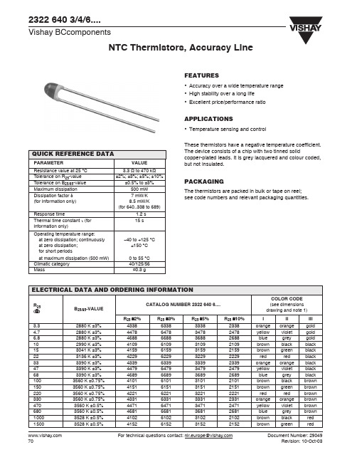
NTC Thermistors, Accuracy Line2322 640 3/4/6....Vishay BCcomponents For technical questions contact: nlr.europe@Document Number: 29049FEATURES• Accuracy over a wide temperature range • High stability over a long life • Excellent price/performance ratioAPPLICATIONS• Temperature sensing and controlThese thermistors have a negative temperature coefficient.元器件交易网2322 640 3/4/6....NTC Thermistors, Accuracy Line Vishay BCcomponents Document Number: 29049For technical questions contact: nlr.europe@ DERATING AND TEMPERATURE TOLERANCESDIMENSIONS in millimeters PHYSICAL DIMENSIONS FOR RELEVANT TYPEMARKINGThe thermistors are marked with coloured bands; seedimensions drawing and “Electrical data and orderinginformation”.MOUNTINGBy soldering in any position.2322 640 6.338 to 6.474.CODENUMBER2322 640.....B max dH1H2maxL P T maxMIN.MAX.6.338 to6.2215.00.6±0.061.0 4.0 6.024±1.52.54 4.06.331 to6.4743.3±0.50.6±0.06− 2.0±1.06.024±1.52.543.0Notes1.Dependent upon R25-tolerance, the band IV is coloured as follows:a)for R25±2%, band IV is coloured redb)for R25±3%, band IV is coloured orangec)for R25±5%, band IV is coloured goldd)for R25±10%, band IV is coloured silver.20003528 K ±0.5%4202620232022202red black red22003977 K ±0.75%4222622232222222red red red27003977 K ±0.75%4272627232722272red violet red33003977 K ±0.75%4332633233322332orange orange red47003977 K ±0.75%4472647234722472yellow violet red68003977 K ±0.75%4682668236822682blue grey red100003977 K ±0.75%4103610331032103brown black orange120003740 K ±2%4123612331232123brown red orange150003740 K ±2%4153615331532153brown green orange220003740 K ±2%4223622332232223red red orange330004090 K ±1.5%4333633333332333orange orange orange470004090 K ±1.5%4473647334732473yellow violet orange680004190 K ±1.5%4683668336832683blue grey orange1000004190 K ±1.5%4104610431042104brown black yellow1500004370 K ±2.5%4154615431542154brown green yellow2200004370 K ±2.5%4224622432242224red red yellow3300004570 K ±1.5%4334633433342334orange orange yellow4700004570 K ±1.5%4474647434742474yellow violet yellowR25(Ω)B25/85-VALUECATALOG NUMBER 2322 640 6....COLOR CODE(see dimensionsdrawing and note 1)R25 ±2%R25±3%R25 ±5%R25±10%I II III元器件交易网2322 640 3/4/6....Vishay BCcomponentsNTC Thermistors, Accuracy Line For technical questions contact: nlr.europe@Document Number: 29049TEMPERATURE DEVIATION AS A FUNCTION OF THE AMBIENT TEMPERATURE.TEMPERATURE DEVIATION AS A FUNCTION OF THE AMBIENT TEMPERATURE.TEMPERATURE DEVIATION AS A FUNCTION OF THE AMBIENT TEMPERATURE.TEMPERATURE DEVIATION AS A FUNCTION OF THE AMBIENT TEMPERATURE.TEMPERATURE DEVIATION AS A FUNCTION OF THE AMBIENT TEMPERATURE.TEMPERATURE DEVIATION AS A FUNCTION OF THE AMBIENT TEMPERATURE.元器件交易网2322 640 3/4/6....NTC Thermistors, Accuracy Line Vishay BCcomponents Document Number: 29049For technical questions contact: nlr.europe@ R T VALUE AND TOLERANCEThese thermistors have a narrow tolerance on the B-value,the result of which provides a very small tolerance on thenominal resistance value over a wide temperature range. Forthis reason the usual graphs of R = f(T) are replaced byResistance Values at Intermediate Temperatures Tables,together with a formula to calculate the characteristics with ahigh precision.FORMULAE TO DETERMINE NOMINALRESISTANCE VALUESThe resistance values at intermediate temperatures, or theoperating temperature values, can be calculated using thefollowing interpolation laws(extended “Steinhart and Hart”):(1)(2)where:A, B, C, D, A1, B1, C1 and D1 are constant valuesdepending on the material concerned; see table below.R ref is the resistance value at a reference temperature (inthis event 25 °C).T is the temperature in K.Formulae numbered (1) and (2) are interchangeable with anerror of max. 0.005 °C in the range 25 °C to 125 °C andmax. 0.015 °C in the range−40 °C to +25 °C.DETERMINATION OF THERESISTANCE/TEMPERATURE DEVIATIONFROM NOMINAL VALUEThe total resistance deviation is obtained by combining the‘R25-tolerance’ and the ‘resistance deviation due toB-tolerance’.When:X = R25-toleranceY = resistance deviation due to B-toleranceZ = complete resistance deviation,then: or Z ≈ X + Y.When:TC = temperature coefficient∆T = temperature deviation,then:The temperature tolerances are plotted in the graphs on theprevious page.Example: at 0 °C, assume X = 5%, Y = 0.89% andTC = 5.08%/K (see T able ), then:A NTC with a R25-value of 10 kΩ has a value of 32.56 kΩbetween −1.17 and +1.17 °C.R (T)R=ref e×A B T⁄C T2⁄D T3⁄+++()T (R) = A1B1RR ref---------ln C1ln2RR ref---------D1ln3RR ref---------+++⎝⎠⎛⎞1–Z1X100---------+⎝⎠⎛⎞1Y100---------+⎝⎠⎛⎞1–×= 100×%∆T ZTC-------=Z15100---------+10.89100-----------+1–×⎩⎭⎨⎬⎧⎫100%×=1.05 1.0089 1–×{} 100% 5.9345% 5.93%≈()=×˙=∆T ZTC-------5.935.08----------- 1.167 °C 1.17≈°C)(===Notes1.Temperature < 25 °C.2.Temperature ≥25 °C.2322 640 3/4/6....Vishay BCcomponentsNTC Thermistors, Accuracy Line For technical questions contact: nlr.europe@Document Number: 290492322 640 3/4/6....NTC Thermistors, Accuracy Line Vishay BCcomponents Document Number: 29049For technical questions contact: nlr.europe@ 5 2.0128 2.16−3.7120.1310 1.6767 1.59−3.6016.7715 1.4042 1.04−3.5014.0420 1.18210.51−3.3911.8225 1.00000.00−3.3010.00300.85000.50−3.208.50350.72590.98−3.117.26400.6226 1.44−3.03 6.23450.5363 1.89−2.94 5.36500.4639 2.33−2.86 4.64550.4029 2.75−2.78 4.03600.3512 3.16−2.71 3.51650.3073 3.56−2.64 3.07700.2698 3.95−2.57 2.70750.2377 4.32−2.50 2.38800.2101 4.69−2.43 2.10850.1864 5.04−2.37 1.86900.1658 5.38−2.31 1.66950.1479 5.72−2.25 1.481000.1323 6.05−2.20 1.321050.1187 6.36−2.14 1.191100.1068 6.67−2.09 1.071150.0964 6.98−2.040.961200.08717.27−1.990.871250.07907.56−1.940.791300.07177.84−1.900.721350.06538.11−1.850.651400.05968.37−1.810.601450.05458.63−1.770.551500.05008.89−1.730.50T oper(°C)R T/R25∆R DUE TOB-TOLERANCE(%)TC(%/K)R25(Ω)2322 640 .....; see note 1 at end of tables6.1092322 640 3/4/6....Vishay BCcomponentsNTC Thermistors, Accuracy Line For technical questions contact: nlr.europe@Document Number: 29049500.4470 2.37−3.00 6.70550.3856 2.80−2.92 5.78600.3339 3.21−2.84 5.01650.2903 3.62−2.76 4.35700.2533 4.01−2.69 3.80750.2218 4.39−2.62 3.33800.1948 4.77−2.56 2.92850.1717 5.13−2.50 2.58900.1518 5.48−2.44 2.28950.1346 5.82−2.38 2.021000.1196 6.15−2.32 1.791050.1067 6.47−2.27 1.601100.0954 6.79−2.22 1.431150.08557.09−2.17 1.281200.07687.39−2.12 1.151250.06917.69−2.07 1.041300.06247.97−2.030.941350.05658.25−1.980.851400.05128.52−1.940.771450.04658.78−1.900.701500.04239.04−.860.63T oper (°C)R T /R 25∆R DUE TO B-TOLERANCE(%)TC (%/K)R 25(Ω)2322 640 .....; see note 1 at end of tables6.1592322 640 3/4/6....NTC Thermistors, Accuracy Line Vishay BCcomponents Document Number: 29049For technical questions contact: nlr.europe@ 950.1346 6.00−2.38 2.961000.1196 6.34−2.32 2.631050.1067 6.68−2.27 2.351100.09547.00−2.22 2.101150.08557.32−2.17 1.881200.07687.62−2.12 1.691250.06917.93−2.07 1.521300.06248.22−2.03 1.371350.05658.50−1.98 1.241400.05128.78−1.94 1.131450.01659.06−1.90 1.021500.04239.32−1.860.93T oper(°C)R T/R25∆R DUE TOB-TOLERANCE(%)TC(%/K)R25(Ω)2322 640 .....; see note 1 at end of tables6.2292322 640 3/4/6....Vishay BCcomponentsNTC Thermistors, Accuracy Line For technical questions contact: nlr.europe@Document Number: 290491400.04079.49−2.07 1.34 1.91 2.771450.03689.79−2.02 1.21 1.73 2.501500.033310.08−1.981.101.562.26T oper (°C)R T /R 25∆R DUE TO B-TOLERANCE(%)TC (%/K)R 25(Ω)2322 640 .....; see note 1 at end of tables6.339 6.479 6.6892322 640 3/4/6....NTC Thermistors, Accuracy Line Vishay BCcomponents Document Number: 29049For technical questions contact: nlr.europe@ For technical questions contact: nlr.europe@Document Number: 29049−5 4.216 1.08 5.249.27511.3813.9119.8128.6742.160 3.2550.89 5.087.1628.79010.7415.3022.1432.565 2.5340.70 4.92 5.575 6.8428.36211.9117.2325.3410 1.9870.52 4.78 4.372 5.366 6.5589.34013.5119.8715 1.5700.34 4.64 3.454 4.239 5.1817.37810.6715.7020 1.2490.17 4.50 2.747 3.372 4.121 5.8698.49212.4925 1.0000.00 4.37 2.200 2.700 3.300 4.700 6.80010.00300.80590.16 4.25 1.773 2.176 2.660 3.788 5.4808.059350.65350.32 4.13 1.438 1.764 2.156 3.072 4.444 6.535400.53300.47 4.02 1.173 1.439 1.759 2.505 3.624 5.330450.43720.62 3.910.9618 1.180 1.443 2.055 2.972 4.372500.36050.77 3.800.79320.973 1.190 1.694 2.451 3.606550.29890.91 3.700.65750.8070.9863 1.405 2.032 2.989600.2490 1.05 3.600.54780.6720.8217 1.170 1.693 2.490650.2084 1.18 3.510.45860.5620.68790.9797 1.417 2.084700.1753 1.31 3.420.38570.4730.57850.8239 1.192 1.753750.1481 1.44 3.330.32580.3990.48870.6960 1.007 1.481800.1256 1.57 3.250.27640.3390.41460.59050.8544 1.256850.1070 1.69 3.160.23550.2890.35320.50310.7278 1.070900.09154 1.81 3.090.20140.2470.30210.43030.62250.9154950.07860 1.93 3.010.17290.2120.25940.36940.53450.78601000.06773 2.04 2.940.14900.1820.22350.31830.46070.67731050.05858 2.15 2.870.12890.1580.19330.27530.39830.58581100.05083 2.26 2.800.11180.1370.16770.23890.34570.50831150.04426 2.37 2.730.09740.11950.14610.20800.30100.44261200.03866 2.47 2.670.08510.10440.12760.18170.26290.38661250.03387 2.57 2.610.07450.09150.11180.15920.23030.33871300.02977 2.67 2.550.06550.08040.09820.13990.20240.29771350.02624 2.77 2.490.05770.07090.08660.12330.17840.26241400.02319 2.86 2.430.05100.06260.07650.10900.15770.23191450.02055 2.96 2.380.04520.05550.06780.09660.13980.20551500.018263.052.330.04020.04930.06030.08580.12420.1826T oper (°C)R T /R 25∆R DUE TO B-TOLERANCE(%)TC (%/K)R 25(k Ω)2322 640 .....; see note 1 at end of tables 6.222 6.272 6.332 6.472 6.682 6.103Document Number: 29049For technical questions contact: nlr.europe@350.67120.80 3.888.05410.0714.77400.5543 1.19 3.77 6.6528.31512.20450.4602 1.57 3.67 5.522 6.90310.12500.3839 1.94 3.57 4.607 5.7598.447550.3219 2.30 3.48 3.862 4.8287.081600.2710 2.65 3.39 3.252 4.067 5.963650.2293 2.99 3.30 2.751 3.439 5.044700.1947 3.33 3.22 2.337 2.921 4.284750.1661 3.66 3.14 1.993 2.492 3.654800.1422 3.98 3.06 1.707 2.134 3.129850.1223 4.29 2.99 1.467 1.834 2.690900.1055 4.60 2.92 1.266 1.583 2.321950.09135 4.90 2.85 1.096 1.370 2.0101000.07937 5.19 2.780.9524 1.190 1.7461050.06919 5.48 2.710.8302 1.038 1.5221100.06050 5.76 2.650.72600.9075 1.3311150.05307 6.04 2.590.63690.7961 1.1681200.04670 6.31 2.530.56040.7005 1.0271250.041216.572.470.49450.61810.9065T oper (°C)R T /R 25∆R DUE TO B-TOLERANCE(%)TC (%/K)R 25(k Ω)2322 640 .....; see note 1 at end of tables6.123 6.153 6.223 For technical questions contact: nlr.europe@Document Number: 290491050.05372 4.47 2.98 1.773 2.5251100.04635 4.70 2.92 1.530 2.1791150.04013 4.93 2.85 1.342 1.8861200.03485 5.15 2.79 1.150 1.6381250.03037 5.36 2.73 1.002 1.4271300.02654 5.57 2.670.8757 1.2471350.02326 5.78 2.610.7675 1.0931400.02044 5.98 2.550.67460.96081450.01802 6.18 2.500.59450.84681500.015926.372.440.52540.7483T oper (°C)R T /R 25∆R DUE TO B-TOLERANCE(%)TC (%/K)R 25(k Ω)2322 640 .....; see note 1 at end of tables 6.333 6.473Document Number: 29049For technical questions contact: nlr.europe@ For technical questions contact: nlr.europe@Document Number: 2904925 1.0000.00 4.95330.0470.0300.78250.37 4.82258.2367.8350.61630.74 4.70203.4289.6400.4883 1.09 4.59161.1229.5450.3892 1.44 4.47128.4182.9500.3120 1.77 4.36103.0146.7550.2515 2.10 4.2683.00118.2600.2038 2.43 4.1567.2695.80650.1660 2.74 4.0654.7978.03700.1359 3.05 3.9644.8663.88750.1118 3.35 3.8736.9052.55800.09240 3.64 3.7830.4943.43850.07670 3.93 3.6925.3136.05900.06395 4.21 3.6121.1030.06950.05354 4.48 3.5317.6725.161000.04501 4.75 3.4514.8521.151050.03798 5.01 3.3712.5317.851100.03218 5.27 3.3010.7015.121150.02736 5.52 3.239.02912.861200.02335 5.77 3.167.70410.971250.019996.013.096.5979.396T oper (°C)R T /R 25∆R DUE TO B-TOLERANCE(%)TC (%/K)R 25(k Ω)2322 640 .....; see note 1 at end of tables 6.334 6.474Document Number: 29049For technical questions contact: nlr.europe@900.08042 3.85 3.28 5.4698.042950.06837 4.10 3.21 4.649 6.8371000.05835 4.35 3.13 3.968 5.8351050.04998 4.59 3.06 3.399 4.9981100.04296 4.82 2.99 2.921 4.2961150.03705 5.05 2.92 2.519 3.7051200.03206 5.28 2.86 2.180 3.2061250.027835.502.801.8922.783T amb (°C)R T /R 25∆R DUE TO B-TOLERANCE(%)TC (%/K)R 25(k Ω)2322 640 .....; see note 1 at end of tables 6.683 6.104Note to Resistance Values At Intermediate Temperature Tables1.Replace dot in last 5 digits of catalog number by a number according to the following details and depending on tolerance onrequired R 25-value: 4 for a tolerance of ±2%; 6 for a tolerance of ±3%; 3 for a tolerance of ±5%; 2 for a tolerance of ±10%.PACKAGINGTAPE SPECIFICATIONSNote1.Taped products with H= 45±1, are available on request.2. D ≤5 max for 6404.338 to 221. For technical questions contact: nlr.europe@ Document Number: 29049Note1. D ≤5 max for 640 3. 338 to 640 4. 221.2.T ≤4 max for 6403. 338 to 6404. 221.Document Number: 29049For technical questions contact: nlr.europe@ Notes1.For R25≥ 100 kΩ the drift requirement is ∆R/R < 5%.2.For R25 from 2.2 kΩ to 10 kΩ, requirement is ±2% max. For technical questions contact: nlr.europe@ Document Number: 29049。
23221961XXXX中文资料

Fig. 4. φ 0.58 mm Cu - leads Minimum distance from resistor body to PCB =1mm Temperature rise (∆T) at the lead end (solder spot) as a function of dissipated power at various leads lengths after mounting
PR01 PHOENIX DO BRASIL LTDA
All rights are reserved . Reproduction whole or in part is prohibited without the written consent of the copyright owner. Revision on 2003/12/21 Page 4 of 13
元器件交易网www.பைடு நூலகம்
Phoenix Passive Components
ELECTRICAL CHARACTERISTICS
DERATING
The power that the resistor can dissipate depends on the operating temperature.
Fig. 2. Maximum dissipation (Pmax) in percentage of rated power as a function of ambient temperature (Tamb)
2302324资料
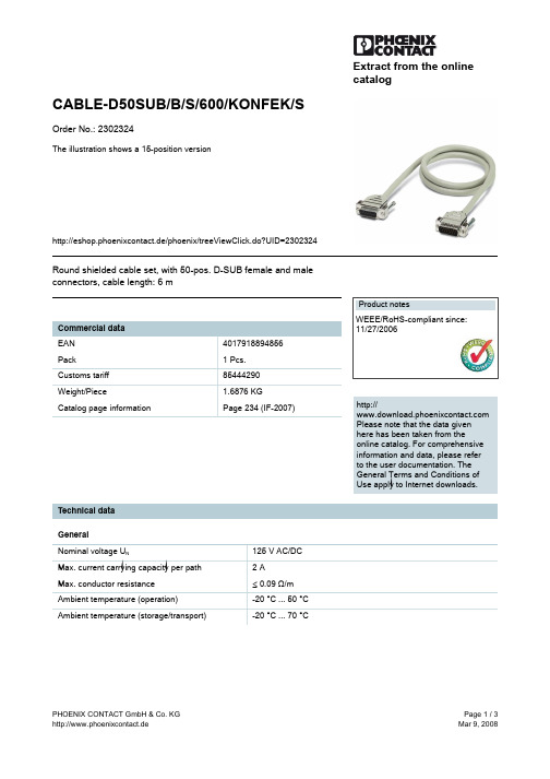
Technical data General Nominal voltage UN Max. current carrying capacity per path Max. conductor resistance Ambient temperature (operation) Ambient temperature (storage/transport) 125 V AC/DC 2A ≤ 0.09 Ω/m -20 °C ... 50 °C -20 °C ... 70 °C
PHOENIX CONTACT GmbH & Co. KG http://www.phoenixcontact.de
Page 1 / 3 Mar 9, 2008
元器件交易网
CABLE-D50SUB/B/S/600/KONFEK/S Order No.: 2302324
http://eshop.phoenixcontact.de/phoenix/treeViewClick.do?UID=2302324
PHOENIX CONTACT GmbH & Co. KG http://www.phoenixcontact.de
Page 2 / 3 Mar 9, 2008
元器件交易网
CABLE-D50SUB/B/S/600/KONFEK/S Order No.: 2302324
http://eshop.phoenixcontact.de/phoenix/treeViewClick.do?UID=2302324
50 50 1 50 1 6m 0.25 mm 24 13.5 mm Tinned copper-braided shield, approx. 85% covering > 200 66.2 mm 40 mm
23226330资料
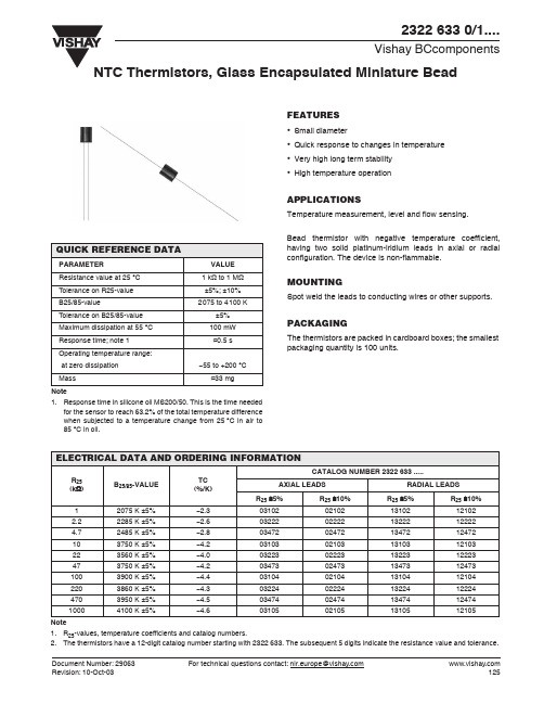
ELECTRICAL DATA AND ORDERING INFORMATION
CATALOG NUMBER 2322 633 ..... R25 (kΩ) 1 2.2 4.7 10 22 47 100 220 470 1000 Note 1. R25-values, temperature coefficients and catalog numbers. 2. The thermistors have a 12-digit catalog number starting with 2322 633. The subsequent 5 digits indicate the resistance value and tolerance. Document Number: 29063 Revision: 10-Oct-03 For technical questions contact: nlr.europe@ 125 B25/85-VALUE 2075 K ±5% 2285 K ±5% 2485 K ±5% 3750 K ±5% 3560 K ±5% 3750 K ±5% 3900 K ±5% 3860 K ±5% 3950 K ±5% 4100 K ±5% TC (%/K) −2.3 −2.6 −2.8 −4.2 −4.0 −4.2 −4.4 −4.3 −4.5 −4.6 AXIAL LEADS R25 ±5% 03102 03222 03472 03103 03223 03473 03104 03224 03474 03105 R25 ±10% 02102 02222 02472 02103 02223 02473 02104 02224 02474 02105 RADIAL LEADS R25 ±5% 13102 13222 13472 13103 13223 13473 13104 13224 13474 13105 R25 ±10% 12102 12222 12472 12103 12223 12473 12104 12224 12474 12105
- 1、下载文档前请自行甄别文档内容的完整性,平台不提供额外的编辑、内容补充、找答案等附加服务。
- 2、"仅部分预览"的文档,不可在线预览部分如存在完整性等问题,可反馈申请退款(可完整预览的文档不适用该条件!)。
- 3、如文档侵犯您的权益,请联系客服反馈,我们会尽快为您处理(人工客服工作时间:9:00-18:30)。
RESISTANCE VALUES AT INTERMEDIATE TEMPERATURES
Toper (°C) ∆T (K) TC (%/K) .0302 −40 −35 −30 −25 −20 −15 −10 −5 0 5 10 15 20 25 30 35 40 45 50 55 60 65 70 75 80 85 90 95 100 105 110 115 120 125 Note 1. Replace dot in last 5 digits of catalog number by 1 for non-insulated or 2 for insulated leads. 33.21 23.99 17.52 12.93 9.636 7.250 5.505 4.216 3.255 2.534 1.987 1.570 1.249 1.000 0.8059 0.6535 0.5330 0.4372 0.3605 0.2989 0.2490 0.2084 0.1753 0.1481 0.1256 0.1070 0.09154 0.07860 0.06773 0.05858 0.05083 0.04426 0.03866 0.03387 0.68 0.66 0.64 0.62 0.59 0.57 0.55 0.52 0.50 0.50 0.50 0.50 0.50 0.50 0.50 0.50 0.50 0.50 0.50 0.55 0.61 0.66 0.72 0.77 0.83 0.89 0.95 1.02 1.08 1.14 1.21 1.27 1.34 1.41 6.57 6.36 6.15 5.95 5.76 5.58 5.40 5.24 5.08 4.92 4.78 4.64 4.50 4.37 4.25 4.13 4.02 3.91 3.80 3.70 3.60 3.51 3.42 3.33 3.25 3.16 3.09 3.01 2.94 2.87 2.80 2.73 2.67 2.61 99.63 71.97 52.56 38.79 28.91 21.75 16.51 12.65 9.766 7.602 5.962 4.710 3.746 3.000 2.418 1.960 1.599 1.312 1.082 0.8966 0.7470 0.6253 0.5259 0.4443 0.3769 0.3211 0.2746 0.2358 0.2032 0.1757 0.1525 0.1328 0.1160 0.1016 R25 (kΩ) 2322 645 .....; see note 1 .0502 166.1 120.0 87.60 64.65 48.18 36.25 27.52 21.08 16.28 12.67 9.936 7.849 6.244 5.000 4.030 3.267 2.665 2.186 1.803 1.494 1.245 1.042 0.8765 0.7405 0.6282 0.5352 0.4577 0.3930 0.3387 0.2929 0.2542 0.2213 0.1933 0.1694 .0103 332.1 239.9 175.2 129.3 96.36 72.50 55.05 42.16 32.56 25.34 19.87 15.70 12.49 10.00 8.059 6.535 5.330 4.372 3.606 2.989 2.490 2.084 1.753 1.481 1.256 1.070 0.9154 0.7860 0.6773 0.5858 0.5083 0.4426 0.3866 0.3387
PACKAGING
The thermistors are packed in cardboard boxes; the smallest packing quantity is 1000 units.
MARKING
The body is coloured with ochre lacquer and not marked.
元器件交易网
2322 645 10/20....
Vishay BCcomponents
NTC Thermistors, Long Lead Sensors
FEATURES
• Accuracy of 0.5 °C between 0 °C and 50 °C • Small diameter • High stability over a long life • Long and flexible leads for special mounting or assembly requirements
APPLICATIONS
• Temperature sensing and control These thermistors have a negative temperature coefficient. The device consists of a chip with two insulated or non-insulated nickel leads.
RT/R25
98
For technical questions contact: nlr.europe@
Document Number: 29051 Revision: 10-Oct-03
MOUNTING
By soldering in any position.
ELECTRICAL DATA AND ORDERING INFORMATION
R25-VALUE (kΩ) 3 5 10 Note 1. Replace dot in last 5 digits of catalog number by 1 for non-insulated or 2 for insulated leads. B25/85-VALUE (K) 3977 3977 3977 CATALOG NUMBER 2322 645 .....(1) .0302 .0502 .A
PARAMETER Resistance value at: 0 °C 50 °C B25/85-value ∆T ensured between 0 °C and 50 °C Temperature coefficient Maximum dissipation Minimum dielectric withstanding voltage (RMS) between leads and coating Operating temperature range Climatic category Mass see Resistance Values Table see Resistance Values Table 3977 K ±0.5 °C see Resistance Values Table 100 mW 500 V −40 to +125 °C 40/125/56 ≈0.2 g VALUE
38 ± 2
0.3 ± 0.03
38 ± 2
0.58 max
6±1
0.25 ± 0.025
Document Number: 29051 Revision: 10-Oct-03
For technical questions contact: nlr.europe@
97
元器件交易网
2322 645 10/20....
Vishay BCcomponents
DERATING
P (%) 100
NTC Thermistors, Long Lead Sensors
Power derating curve.
0 40 25 0 55 85 Tamb ( o C) 125
DIMENSIONS in millimeters
Component outline for 2322 645 10... series.
2.4 max 2.4 max
Component outline for 2322 645 20... series.
2.4 max
2.4 max
8 max
8 max