UCLAMP1201P中文资料
ADuM1200_1201中文资料

SOIC-8 窄体无铅封装
北京晶圆智通科技有限公司 Tel:010-51654997
Fax:010-82784963
1
三、应用领域: 多通道的隔离 SPI 接口和数字转换器的隔离 RS-232/RS-422/RS-485 收发器隔离 数字现场总线隔离 混合动力汽车,蓄电池监控,电机驱动 四、典型工作参数
Min 4.5 4.5
0.7VDD VDD-0.1
-35
Typ
Max
5
5.5
5
5.5
0.50
0.60
0.19
0.25
1.1
1.4
0.5
0.8
0.8
1.1
0.8
1.1
0.3VDD 5.0
0.0
0.1
+35
VDD1=VDD2=3V;TA=25℃
工作参数
符电压
VDD1
2.7
3
3.6
图 1 中的两组线圈起到脉冲变压器的作用,输入端逻辑电平的变化会引起一个窄脉冲 (2ns),经过脉冲变压器耦合到解码器,然后再经过一个施密特触发器的波形变换输出标准 的矩形波,如果输入端逻辑电平超过 2µS 都没有任何变化,则校正电路会产生一个适当极 性的校正脉冲,以确保变压器直流端输出信号的正确性,如果解码器一端超过 5µS 都没有 收到任何校正脉冲,则会认为输入端已经掉电或不工作,由看门狗电定时器电路,将输出端
ADuM1200/1201
ADUM1200/1201 双通道隔离器产品系列
一、功能描述: ADuM120x 是基于 ADI(Analog device, inc)公司的 iCoupler 磁耦隔离技术的双通道数
奥特梅尔LSD101-T1200 T1206 T1208 T1251黑白线扫描CCD驱动板用户手册说
查询TCD1200D供应商捷多邦,专业PCB打样工厂,24小时加急出货LSD101-T1200LSD101-T1206LSD101-T1208LSD101-T1251单路模拟输出黑白线扫描CCD驱动板B/W LINESCAN CCD DRIVER用户手册©2007 All Rights Reserved目 录产品功能描述 (1)主要技术指标 (2)驱动板的使用 (3)1.注意事项 (3)2. IO输入输出接口定义 (3)3. 功能设置拨码开关 (4)4. 使用驱动板 (5)信号及时序 (5)1. 输出信号描述 (5)2. 内同步驱动模式 (5)3. 外同步工作模式 (6)积分步长及积分时间设定 (7)CCD模拟输出信号调整 (8)外形及尺寸 (9)修订信息 (10)产品功能描述LSD101-T1200/T1206/T1208/T1251驱动板是我公司专为日本TOSHIBA(东芝)公司生产的TCD1200D/TCD1206SUP/TCD1208AP/TCD1251UD黑白线扫描CCD设计的驱动电路板,驱动板设计上结合了我公司技术人员多年线扫描CCD 驱动的设计应用经验,采用高速同步驱动电路设计技术,产品具有时序一致性好、稳定可靠的优点。
驱动板主要具备以下功能及特点:严格按照芯片手册的定义提供满足驱动要求的驱动信号及时序;采用小型化表面贴装元件设计的小尺寸单板式驱动结构;提供完全内外两种同步驱动模式,内同步驱动上电即可工作;将CCD原始输出的反向偏置输出信号转换为正向零偏置模拟输出信号;积分时间可分16级线性调整;积分时间步长4级可设定;驱动频率2档可设定;提供行有效输出信号及像素采样输出时钟;具备一定的电源过流、过热保护及抗干扰电路措施。
图1 LSD101-T1200/T1206/T1208/T1251实物标注图主要技术指标表1 主要技术指标参数技术指标最小值典型值最大值LSD101-T1200LSD101-T1206 LSD101-T12081MHz 2MHz 2MHz 驱动频率①LSD101-T1251 2MHz 4MHz 4MHz LSD101-T1200LSD101-T1206 —— —— 891(Hz ) LSD101-T1208 —— —— 900(Hz ) 行扫描频率②LSD101-T1251———— 1432(Hz )数字输出信号高电平电压 4.5V 5.0V VCC 数字输出信号低电平电压 0V 0.1V 0.7V EX_INT 输入信号高电平电压 3.0V 4.0V VCC EX_INT 输入信号低电平电压 0V 0.2V 0.5V 模拟输出信号电压 0.1V —— VCC① 驱动频率2档可设定,通过驱动板上拨码开关设定。
adum1201 电路设计 i2c 隔离
adum1201 电路设计 i2c 隔离1.我们需要为i2c通信设计一个隔离电路。
(We need to design an isolation circuit for i2c communication.)2.这个电路需要能够有效地隔离i2c信号。
(This circuit needs to effectively isolate the i2c signal.)3.我们要确保隔离电路不会影响i2c通信的稳定性。
(We need to ensure that the isolation circuit will not affect the stability of i2c communication.)4.隔离电路需要能够传输i2c数据信号。
(The isolation circuit needs to be able to transmit i2c data signals.)5.我们需要考虑隔离电路对i2c通信速度的影响。
(We need to consider the impact of the isolation circuit on the speed of i2c communication.)6.这个电路需要满足i2c通信的标准要求。
(This circuit needs to meet the standard requirements for i2c communication.)7.我们需要选择合适的隔离元件来设计这个电路。
(We need to select the appropriate isolation components to design this circuit.)8.这个隔离电路需要能够在不同工作条件下都能正常工作。
(This isolation circuit needs to function properly under different working conditions.)9.我们需要保证隔离电路对i2c数据的传输不会出现误差。
Fluke 902 HVAC Clamp Meter Users Manual

®PN 2547887 May 2006 Rev. 1, 3/07© 2006-2007 Fluke Corporation. All rights reserved. Printed in China.All product names are trademarks of their respective companies.902HVAC Clamp MeterUsers ManualLIMITED WARRANTY AND LIMITATION OF LIABILITY This Fluke product will be free from defects in material and workmanship for three years from the date of purchase. This warranty does not cover fuses, disposable batteries, or damage from accident, neglect, misuse, alteration, con-tamination, or abnormal conditions of operation or handling. Resellers are not authorized to extend any other warranty on Fluke’s behalf. To obtain service during the warranty period, contact your nearest Fluke authorized service cen-ter to obtain return authorization information, then send the product to that Service Center with a description of the problem.THIS WARRANTY IS YOUR ONLY REMEDY. NO OTHER WARRANTIES, SUCH AS FITNESS FOR A PARTICULAR PURPOSE, ARE EXPRESSED OR IMPLIED. FLUKE IS NOT LIABLE FOR ANY SPECIAL, INDIRECT, INCIDEN-TAL OR CONSEQUENTIAL DAMAGES OR LOSSES, ARISING FROM ANY CAUSE OR THEORY. Since some states or countries do not allow the exclusion or limitation of an implied warranty or of incidental or consequential dam-ages, this limitation of liability may not apply to you.Fluke CorporationP.O. Box 9090 Everett, WA 98206-9090 U.S.A. Fluke Europe B.V. P.O. Box 1186 5602 BD Eindhoven The Netherlands11/99Table of ContentsTitle Page Introduction (1)Contacting Fluke (2)Safety Information (3)Symbols (5)Getting Acquainted with the Meter (6)Using the Meter (10)AC and DC Voltage Measurement (10)Resistance and Continuity (11)Microamps µA Measurement (12)Temperature (13)Capacitance (16)AC Current Measurement (16)Backlight (18)MIN MAX Recording Mode (18)Display HOLD (19)Auto Off (19)Maintenance (20)Cleaning the Meter (20)Battery Replacement (21)Specifications (23)Electrical Specifications (23)General Specifications (24)902Users ManualList of TablesTable Title Page1. 902 HVAC Clamp Meter Features (7)2. Display Features (9)List of FiguresFigure Title Page1. 902 HVAC Clamp Meter Features (6)2. Display Features (8)3. Testing a Flame Rod (13)4. Temperature Measurement (15)5. Proper AC Current Measurement (17)6. Battery Replacement (22)902Users Manual902 IntroductionThe Fluke 902 is a hand-held battery-operated HVAC Clamp Meter (“the Meter”) that measures:•AC current•DC current (up to 200 µA for flame rod testing)•AC and DC voltages•Capacitance•Resistance•Continuity•Temperature in both Celsius (°C) and Fahrenheit (°F) The Meter comes with:•Two AA alkaline batteries (installed)•Users Manual•Soft carrying case•TL75 Test Leads (one pair)•80BK Integrated DMM Temperature Probe902Users ManualContacting FlukeTo contact Fluke, call one of the following telephone numbers:USA: 1-888-99-FLUKE (1-888-993-5853)Canada: 1-800-36-FLUKE (1-800-363-5853)Europe: +31 402-675-200Japan: +81-3-3434-0181Singapore: +65-738-5655Anywhere in the world: +1-425-446-5500Or visit Fluke’s Web site at: . Register the Meter at: HVAC Clamp MeterFlukeContacting Safety InformationA “XW Warning” statement defines hazardous conditions and actions that could cause bodily harm or death.A “W Caution” statement identifies conditions and actionsthat could damage the Meter or the equipment under test.XW Read First: Safety InformationTo ensure safe operation and service of theMeter, follow these instructions:•Read the Users Manual before use andfollow all safety instructions.•Use the Meter only as specified in theUsers Manual; otherwise, the Meter'ssafety features may be impaired.•Avoid working alone so assistance can berendered.•Never use the Meter on a circuit withvoltages higher than 600 V or a frequencyhigher than 400 Hz fundamental. The Metermay be damaged.•Never measure ac current while the testleads are inserted into the input jacks.•Do not use the Meter or test leads if theylook damaged.•Use extreme caution when working aroundbare conductors or bus bars. Contact withthe conductor could result in electricshock.902Users Manual•Use caution when working with voltages above 60 V dc or 30 V ac rms or 42 V acpeak. Such voltages pose a shock hazard.•Clean the case with a damp cloth and mild detergent only. Do not use abrasives orsolvents.•To avoid false readings that can lead to electrical shock and injury, replace thebatteries as soon as the low batteryindicator (B)appears. As the Meter getsto the point where the low batteries affectthe readings, the Meter locks and nomeasurements can be made until thebatteries are changed.•Do not hold the Meter anywhere beyond the tactile barrier, see Figure 1.•Adhere to local and national safety codes.Individual protective equipment must beused to prevent shock and arc blast injurywhere hazardous live conductors areexposed.HVAC Clamp MeterSymbolsSymbolsThe following symbols are found on the Meter or in this manual.,May be used on hazardous live conductorsW Risk of danger. Important information. See UsersManual.X Hazardous voltage. Risk of electric shock.T Double insulationB Battery)Complies with Canadian and US StandardsP Conforms to relevant European Union directivesJ Earth groundF DC (Direct Current)B AC (Alternating Current)~Do not dispose of this product as unsorted municipalwaste. Contact Fluke or a qualified recycler fordisposal.;Conforms to relevant Australian standardsN10140s Inspected and licensed by TÜV Product Services902Users ManualGetting Acquainted with the Meter Refer to Figures 1 and 2 and Tables 1 and 2 to become more acquainted with the Meter’s features.Figure 1. 902 HVAC Clamp Meter FeaturesHVAC Clamp MeterGetting Acquainted with the Meter Table 1. 902 HVAC Clamp Meter FeaturesNumber DescriptionA Backlight ButtonB Jaw ReleaseC Tactile BarrierD JawsE Hold ButtonF Rotary Switch:V DC and AC voltageP Resistance and continuityG DC microampsF Degrees Fahrenheit / degrees CelsiusL CapacitanceK AC currentG LCDH Min Max ButtonI AC/DC, °F/°C ButtonJ Input Terminals902Users ManualFigure 2. Display FeaturesHVAC Clamp MeterGetting Acquainted with the MeterTable 2. Display FeaturesNumber IndicationA Battery indicator -The batteries are low and need to be changed. XW Warning: To avoid false readings, which could lead to possible electric shock or personal injury, replace the batteries as soon as the battery indicator appears.B Indicates the presence of high voltageC Indicators for minimum and maximum recording modeD Display Hold is activeE VoltsF AmpsG °F - Degrees Fahrenheit °C - Degrees Celsius e - OhmsM - MicroampsN - MicrofaradsDC - Direct CurrentAC - Alternating Current902Users ManualUsing the MeterAC and DC Voltage MeasurementTo measure AC or DC voltage:1.Insert the test leads into the Meter.2.Turn the rotary switch to V.3.Press A to choose AC or DC voltage. The displayreflects the chosen voltage mode.e the test leads to take the measurement. The Meterreading appears on the display.NoteWhen a measured voltage is above 30 V,Z appears on the display. When the voltage dropsbelow 30 V, Z disappears.HVAC Clamp MeterUsing the MeterResistance and ContinuityTo measure resistance or continuity:XW WarningTo avoid false readings that can lead toelectrical shock and injury, de-energize thecircuit before taking the measurement.1.Insert the test leads into the Meter.2.Turn the rotary switch to P.3.Take the measurement. The resistance readingappears on the display.•If the resistance is shorted, the Meter beeps and shows a reading < 30 Ω.•If the resistance is open or exceeds the Meter’s range, the display reads OL.902Users ManualMicroamps µA MeasurementThe µA dc (G) function on the Meter is primarily for HVAC flame rod testing. To test a heating system flame rod (refer to Figure 3):1.Turn the heating unit off and locate the wire betweenthe gas-burner controller and the flame rod.2.Break this connection.3. Turn the rotary switch on the Meter to G.ing alligator clips, connect test leads between theflame sensor probe and control-module wire.5.Turn heating unit on and check the reading on theMeter.6.Refer to the heating unit documentation for what thedesired reading should be.HVAC Clamp MeterUsing the MeterFigure 3. Testing a Flame RodTemperatureThe Meter measures temperature in either Celsius (°C) or Fahrenheit (°F).To measure temperature (refer to Figure 4):902Users Manual1.Connect the 80BK Integrated DMM TemperatureProbe to the input jacks noting correct polarity of theprobe.2.Turn the rotary switch to F.3.Press A to select °C or °F. The display reflects thechosen temperature mode.4.Position the probe to take the measurement. Thereading appears on the display.NoteTo meet stated accuracy, the 80BK and Metermust be at the same temperature.XW WarningTo avoid possible electric shock DO NOT applythe probe tip to any conductor that is greaterthan 30 V ac, 42 V peak or 60 V dc to earth.Using the MeterFigure 4. Temperature MeasurementUsers ManualCapacitanceTurn off circuit power, then disconnect and discharge the capacitor before measuring capacitance. Turn the Meter’s rotary switch to capacitance (L).If the capacitor requires more discharging, diSC is displayed while the capacitor discharges. When measuring, be sure to note the correct polarity of the capacitor.AC Current MeasurementXW WarningTo avoid electrical shock and injury:•Remove Test Leads before making current measurements.•Do not hold the Meter anywhere beyondthe tactile barrier, see Figure 1.Turn the rotary switch to AC current (K). When measuring AC current, it is necessary that the measured wire be properly seated within the clamp jaws. The wire being measured should be centered within the jaws, below the horizontal line located on the clamp. Also note that currents moving in different directions will cancel each other out, so one wire must be measured at a time for a correct measurement (see Figure 5).Using the MeterFigure 5. Proper AC Current MeasurementUsers ManualBacklightPress C to toggle the backlight on and off. The backlight automatically turns off after 2 minutes.To disable the automatic 2-minute backlight timeout, hold down C while turning the Meter on.MIN MAX Recording ModeThe MIN MAX recording mode captures the minimum and maximum input values. When a new high or low is detected, the Meter beeps.To use this feature:1.Put the Meter into the desired measurement functionand range.2.Press J to enter MIN MAX Mode. MAX is displayedand the highest reading detected since entering MINMAX is displayed.3.Press J to step through the minimum (MIN) andpresent readings.4.To pause MIN MAX recording without erasing storedvalues, press I. K is displayed.5.To resume MIN MAX recording, press I again.6.To exit and erase stored readings, press J for atleast two seconds.Using the MeterDisplay HOLDXW WarningTo avoid possible electric shock or personalinjury, when Display HOLD is activated, beaware that the display will not change whenyou apply a different voltage.In the Display HOLD mode, the Meter freezes the display. The Meter also beeps every 4 seconds and H flashes to remind the user.Press I to activate Display HOLD; H is displayed and the reading is captured.To exit and return to normal operation, press I.Auto OffThe Meter automatically turns off after 20 minutes. The rotary switch must be turned to “OFF” and then turned back on for the Meter to restart. Auto Off is disabled during Min Max mode. To disable Auto Off, hold J when turning the Meter on.Users ManualMaintenanceXW WarningTo avoid possible electric shock or personalinjury, repairs or servicing not covered in thismanual should be performed only by qualifiedpersonnel.Cleaning the MeterXW WarningTo avoid electrical shock, remove any inputsignals before cleaning.W CautionTo avoid damaging the Meter, do not usearomatic hydrocarbons or chlorinated solvents for cleaning. These solutions will react with the plastics used in the Meter.Clean the instrument case with a damp cloth and mild detergent.MaintenanceBattery ReplacementXW WarningTo avoid false readings that could lead topossible electric shock or personal injury,replace the batteries as soon as the lowbattery indicator (B) appears.Disconnect the test leads before replacing thebatteries.To replace the batteries (refer to Figure 6):1.Turn the rotary switch to “OFF” and remove the testleads from the terminals.e a Phillips screwdriver to loosen the batterycompartment door screw, and remove the door fromthe case bottom.3.Remove the batteries.4.Replace the batteries with two new AA batteries.5.Reattach the battery compartment door to the casebottom and tighten the screw.Users ManualFigure 6. Battery ReplacementSpecifications SpecificationsElectrical SpecificationsFunction Range Resolution Accuracy Voltage DC 0 – 600 V 0.1 V 1 % ± 5 countsVoltage AC (True Rms) 0 – 600 V 0.1 V1 % ± 5 counts(50/60 Hz)Current AC (True Rms) 0 – 600 A 0.1 A2.0 % ± 5 counts(50/60 Hz)Current DC 0 - 200 µA 0.1µA 1.0 % ± 5 countsResistance 0 – 999 Ω0 – 9999 Ω0.1 Ω1.0 Ω1.5 % ± 5 countsContinuity <30ΩTemperature -10 to 400 °C 0.1 °C 1 % ± 0.8 °CCapacitance 1-100 µF100-1000 µF0.1 µF1 µF1.9 % ± 2 countsUsers ManualGeneral SpecificationsOperating Temperature -10 °C to +50 °CStorage Temperature -40 °C to +60 °COperating Humidity Non condensing (< 10 °C)90 % RH (10 °C to 30 °C)75 % RH (30 °C to 40 °C)45 % RH (40 °C to 50 °C)(Without Condensation) Operating Altitude 2500 meters above mean sealevelStorage Altitude 12,000 meters above meansea levelIP Rating IP 30 per IEC 60529 Vibration Requirements MIL-PRF-28800F Class 2random vibrationEMI, RFI, EMC EMI: instrument unspecified foruse in EMC field • 0.5 V /MeterEMC: Meets all applicablerequirements in EN61326-1Temperature Coefficients 0.1 x (specified accuracy)/ °C (<18 °C or >28 °C)HVAC Clamp Meter Specifications25Size (H X W X L) 9.1 x 3.8 x 1.7 inches (240 x 80 x 40 mm) Weight1.1 lb (310 g)Design Standards and Compliance IEC 61010, IEC 61010-2-032,CEAgency ApprovalsP ) ; sN10140Over-voltage Category600 V, CAT III per IEC 1010-1CAT III equipment is designed to protect against transients in equipment in fixed-equipment installations, such asdistribution panels, feeders and short branch circuits, and lighting systems in large buildings.Power Requirements Two AA Batteries , NEDA 15 A, IEC LR61.888.610.7664**************************Fluke -Direct .com902Users Manual26**************************1.888.610.7664。
PS690U系列保护测控装置说明V1.4
* 本说明书可能会被修改,请注意核对实际产品与说明书的版本是否相符 * 2010 年 8 月 第 1 版 第 1 次印刷
目
次
第一章 装置概述 ....................................................................................................................................................... 1 1 概述 .................................................................................................................................................................... 1 1.1 主要用途及方案 ......................................................................................................................................... 1 1.2 技术特点 ..................................................................................................................................................... 1 1.3 保护装置型号及配置 .........................................
阿特克(Altech Corp.)UL 系列微型箔式过流保护器说明文件说明书

U L 489A N N E XU L 508U L 1077U L 1077E q u i p m e n t B r e a k e r sE a r t h L e a k a g e C i r c u i t B r e a k e r s• 35 Royal Road • Flemington, NJ 08822-6000 • P 908.806-9400 • F 908.806.9490 • 10UL(AC),DL(DC) SeriesUL489 Miniature Molded Case Circuit BreakersCurrent/ Voltage RatingUL-Series DL-SeriesCalibration TemperatureAmbient Temperature Storage Temperature Terminal Size Acceptability Terminal Torque (min/max)Electrical Life Mechanical Life Vibration ResistanceResistance to mechanical shocks Degree of protection acc. IEC/EN 60529Mounting Orientation0.3 - 63A/ 240V AC, 0.3-32A/ 480Y/277V AC* (48V DC / pole pending)0.3 - 63A/ 125/ 250V DC 40ºC (104ºF)-25ºC to +55ºC (-13ºF to 131ºF )-40ºC to +70ºC (-40ºF to 158ºF )T op: 18-3 AWG; Bottom: 18-2 AWG 2 Nm (17.7 lb.in.) / 2.5Nm (22.2 lb.in)6,000 switching cycles ON/ OFF 10,000 switching cycles ON/ OFF> 15g according to DIN EN 60069-2-59 during a load with I 1= 1.05 x I N 25g @ 11ms IP20 In any planeIEC 60947-2Short Circuit Tested•Available in AC and DC models •DIN Rail Mounted •17.5mm width •Thermal Magnetic•Current Limiting (UL tested)•240V , 480Y/277V AC, 50/60Hz•125V DC (1 pole); 250V DC (2 pole)•10kA Short Circuit Interrupting Capacity •HACR T ype 40°C •Line/Load reversibleLISTED CUSE329510C.B.No.Poles Type 0.3-32A 40-63A 1AC 10kA @ 120, 240,10kA @ 120,277V 240V 2-3AC10kA @ 120, 240,10kA @ 120480Y/277V240VNo.Poles Type 0.3-3240-63A 1AC 15kA@240V 15kA@240V 2-3AC15kA@415V10kA@415VNo.Poles Type 0.3-32A 40-63A 1DC 10kA @ 125V 10kA @ 125V 2DC10kA @ 250V10kA @ 250V*One device, dual voltage ratings.Short Circuit Interrupting Capacity According to UL 489Short Circuit Interrupting CapacityAccording to IEC 60947-2, DIN EN 60947-2U L 489A N N E XU L 508U L 1077U L 1077E q u i p m e n t B r e a k e r sE a r t h L e a k a g e C i r c u i t B r e a k e r s • 35 Royal Road • Flemington, NJ 08822-6000 • P 908.806-9400 •F 908.806.9490 • 11D-Characteristics AC1.05xRC1.35xRC10xRC16xRCD-Characteristics DC1.05xRC1.35xRC14xRC22.4xRC*The value of each characteristic is shown vertically beneath its corresponding heading.Characteristic Trip Boundaries Trip-Characteristics*ApplicationsC-Characteristics ACC-Characteristics DCThermal TripLighting Control CircuitsWiring Protection Business Equipment AppliancesTransformersPower Supplies HeatersMust not Trip>100ms Must Trip <1hr Must not Trip>100ms Must Trip at 100ms Magnetic TripLowInrush High InrushMotorsReactive LoadTelecommu-nications/Computer EquipmentPower Supplies1.05xRC1.35xRC5xRC10xRC1.05xRC1.35xRC7xRC14xRCWarning!This information should only be used as a selection guide. T he use of a Miniature Circuit Breaker in an application with a certain T rip-Characteristic always requires prototype testing! It is the responsibility of the circuit design engineer to select the appropriate Miniature Circuit Breaker for his specific application.1 Pole2 Pole3 Pole17.5 mm36.5 m m 36.8 m m35 mm52.5 mm68.4 mm 51.5 mm30.5 mm51.5 mm37.5 mm25.5 mm 14.5 mm45 m m105.3 m m52.5 m m34.5 m m 8467Dimensions in mmTrip CharacteristicVoltage Rating Rated Current No. of PolesApproval for heating,refrigerating and air conditioning devices.Approval Circuit Diagram Short Circuit RatingProduct SeriesIndividual Part Number is shown Marking DetailsU L 489A N N E XU L 508U L 1077U L 1077E q u i p m e n t B r e a k e r sE a r t h L e a k a g e C i r c u i t B r e a k e r s• 35 Royal Road • Flemington, NJ 08822-6000 • P 908.806-9400 • F 908.806.9490 • 12C -TripCharacteristicLISTED C USE329510C.B.Application Examples:Low inrush motors, resistive loads, wiring protection, receptacles,lighting, and control circuit applications. Relatively short thermal trip delay and medium magnetic trip point.Standard Pack: 12Weight:0.3-32A:1.74kg (3.83lb.)40-63A:1.98kg (4.37lb.)Standard Pack: 6Weight:0.3-32A:1.74kg (3.83lb.)40-63A:1.98kg (4.37lb.)Standard Pack: 4Weight:0.3-32A:1.74kg (3.83lb.)40-63A:1.98kg (4.37lb.)Rated Type/ Rated Current Cat. No. Voltage 0.3A 1C03UL 277V AC 0.5A 1C05UL 277V AC 1.0A 1C1UL 277V AC 1.6A 1C1.6UL 277V AC 2.0A 1C2UL 277V AC 3.0A 1C3UL 277V AC 4.0A 1C4UL 277V AC 5.0A 1C5UL 277V AC 6.0A 1C6UL 277V AC 8.0A 1C8UL 277V AC 10A 1C10UL 277V AC 12A 1C12UL 277V AC 13A 1C13UL 277V AC 15A 1C15UL 277V AC 16A 1C16UL 277V AC 20A 1C20UL 277V AC 25A 1C25UL 277V AC 30A 1C30UL 277V AC 32A 1C32UL 277V AC 40A 1C40UL 240V AC 50A 1C50UL 240V AC 60A 1C60UL 240V AC 63A 1C63UL 240V ACOne PoleThree PoleTwo PoleAdd-on Neutral PoleRated Type/ Rated Current Cat. No. Voltage 0.3A 2C03UL 480Y/277V AC 0.5A 2C05UL 480Y/277V AC 1.0A 2C1UL 480Y/277V AC 1.6A 2C1.6UL 480Y/277V AC 2.0A 2C2UL 480Y/277V AC 3.0A 2C3UL 480Y/277V AC 4.0A 2C4UL 480Y/277V AC 5.0A 2C5UL 480Y/277V AC 6.0A 2C6UL 480Y/277V AC 8.0A 2C8UL 480Y/277V AC 10A 2C10UL 480Y/277V AC 12A 2C12UL 480Y/277V AC 13A 2C13UL 480Y/277V AC 15A 2C15UL 480Y/277V AC 16A 2C16UL 480Y/277V AC 20A 2C20UL 480Y/277V AC 25A 2C25UL 480Y/277V AC 30A 2C30UL 480Y/277V AC 32A 2C32UL 480Y/277V AC 40A 2C40UL 240V AC 50A 2C50UL 240V AC 60A 2C60UL 240V AC 63A 2C63UL 240V ACRated Type/ Rated Current Cat. No. Voltage 0.3A 3C03UL 480Y/277V AC 0.5A 3C05UL 480Y/277V AC 1.0A 3C1UL 480Y/277V AC 1.6A 3C1.6UL 480Y/277V AC 2.0A 3C2UL 480Y/277V AC 3.0A 3C3UL 480Y/277V AC 4.0A 3C4UL 480Y/277V AC 5.0A 3C5UL 480Y/277V AC 6.0A 3C6UL 480Y/277V AC 8.0A 3C8UL 480Y/277V AC 10A 3C10UL 480Y/277V AC 12A 3C12UL 480Y/277V AC 13A 3C13UL 480Y/277V AC 15A 3C15UL 480Y/277V AC 16A 3C16UL 480Y/277V AC 20A 3C20UL 480Y/277V AC 25A 3C25UL 480Y/277V AC 30A 3C30UL 480Y/277V AC 32A 3C32UL 480Y/277V AC 40A 3C40UL 240V AC 50A 3C50UL 240V AC 60A 3C60UL 240V AC 63A 3C63UL 240V ACRated Type/ Rated Current Cat. No. Voltage 0.3-32A N32UL 480/277V AC 40-63A N63UL 240V ACStandard Pack: 6Weight:0.99kg (2.18 lb.)Standard Dual Connection Terminal•Box clamp terminals Top: 18-3 AWG;Bottom: 18-2 AWG (Line/Load reversible)•Ring tongue terminalsRing tongueBox clamp*May differ by manufacturer. T op terminal ring tongue max. thickness 1.6mm.18.3 mm (0.72 in.)M5 screw11.3 mm (0.44 in.)m a x . 8-12 m m (0.31-0.47 i n .)5.3 m m (0.21 i n .)UL - SeriesU L 489A N N E XU L 508U L 1077U L 1077E q u i p m e n t B r e a k e r sE a r t h L e a k a g e C i r c u i t B r e a k e r s • 35 Royal Road • Flemington, NJ 08822-6000 • P 908.806-9400 •F 908.806.9490 • 13Application Examples:High inrush motors, transformers, power supplies, heaters and reactive loads. Relatively long thermal trip delay and very high magnetic trip point.LISTED C USE329510C.B.Standard Pack: 12Weight:0.3-32A:1.74kg (3.83lb.)40-63A:1.98kg (4.37lb.)Standard Pack: 6Weight:0.3-32A:1.74kg (3.83lb.)40-63A:1.98kg (4.37lb.)Standard Pack: 4Weight:0.3-32A:1.74kg (3.83lb.)40-63A:1.98kg (4.37lb.)Rated Type/ Rated Current Cat. No. Voltage 0.3A 1D03UL 277V AC 0.5A 1D05UL 277V AC 1.0A 1D1UL 277V AC 1.6A 1D1.6UL 277V AC 2.0A 1D2UL 277V AC 3.0A 1D3UL 277V AC 4.0A 1D4UL 277V AC 5.0A 1D5UL 277V AC 6.0A 1D6UL 277V AC 8.0A 1D8UL 277V AC 10A 1D10UL 277V AC 12A 1D12UL 277V AC 13A 1D13UL 277V AC 15A 1D15UL 277V AC 16A 1D16UL 277V AC 20A 1D20UL 277V AC 25A 1D25UL 277V AC 30A 1D30UL 277V AC 32A 1D32UL 277V AC 40A 1D40UL 240V AC 50A 1D50UL 240V AC 60A 1D60UL 240V AC 63A 1D63UL 240V ACOne PoleThree PoleTwo PoleAdd-on Neutral PoleRated Type/ Rated Current Cat. No. Voltage 0.3A 2D 03UL 480Y/277V AC 0.5A 2D 05UL 480Y/277V AC 1.0A 2D 1UL 480Y/277V AC 1.6A 2D 1.6UL 480Y/277V AC 2.0A 2D 2UL 480Y/277V AC 3.0A 2D 3UL 480Y/277V AC 4.0A 2D 4UL 480Y/277V AC 5.0A 2D 5UL 480Y/277V AC 6.0A 2D 6UL 480Y/277V AC 8.0A 2D 8UL 480Y/277V AC 10A 2D 10UL 480Y/277V AC 12A 2D 12UL 480Y/277V AC 13A 2D 13UL 480Y/277V AC 15A 2D 15UL 480Y/277V AC 16A 2D 16UL 480Y/277V AC 20A 2D 20UL 480Y/277V AC 25A 2D 25UL 480Y/277V AC 30A 2D 30UL 480Y/277V AC 32A 2D 32UL 480Y/277V AC 40A 2D 40UL 240V AC 50A 2D 50UL 240V AC 60A 2D 60UL 240V AC 63A 2D 63UL 240V ACRated Type/ Rated Current Cat. No. Voltage 0.3A 3D 03UL 480Y/277V AC 0.5A 3D 05UL 480Y/277V AC 1.0A 3D 1UL 480Y/277V AC 1.6A 3D 1.6UL 480Y/277V AC 2.0A 3D 2UL 480Y/277V AC 3.0A 3D 3UL 480Y/277V AC 4.0A 3D 4UL 480Y/277V AC 5.0A 3D 5UL 480Y/277V AC 6.0A 3D 6UL 480Y/277V AC 8.0A 3D 8UL 480Y/277V AC 10A 3D 10UL 480Y/277V AC 12A 3D 12UL 480Y/277V AC 13A 3D 13UL 480Y/277V AC 15A 3D 15UL 480Y/277V AC 16A 3D 16UL 480Y/277V AC 20A 3D 20UL 480Y/277V AC 25A 3D 25UL 480Y/277V AC 30A 3D 30UL 480Y/277V AC 32A 3D 32UL 480Y/277V AC 40A 3D 40UL 240V AC 50A 3D 50UL 240V AC 60A 3D 60UL 240V AC 63A 3D 63UL 240V ACRated Type/ Rated Current Cat. No. Voltage 0.3-32A N32UL 480/277V AC 40-63A N63UL 240V ACStandard Pack: 6Weight:0.99kg (2.18 lb.)Standard Dual Connection Terminal•Box clamp terminals T op: 18-3 AWG;Bottom: 18-2 AWG (Line/Load reversible)•Ring tongue terminalsRing tongueBox clamp*May differ by manufacturer. T op terminal ring tongue max. thickness 1.6mm.18.3 mm (0.72 in.)M5 screw11.3 mm (0.44 in.)m a x . 8-12 m m (0.31-0.47 i n .)5.3 m m (0.21 i n .)D -TripCharacteristicUL - SeriesU L 489A N N E XU L 508U L 1077U L 1077E q u i p m e n t B r e a k e r sE a r t h L e a k a g e C i r c u i t B r e a k e r s• 35 Royal Road • Flemington, NJ 08822-6000 • P 908.806-9400 • F 908.806.9490 • 14C -Trip (DC)CharacteristicApplication Examples:Telecommunication equipment,computer equipment, uninterruptable power supplies.Standard Pack: 12Weight:0.3-32A:1.86kg (4.1lb.)40-63A:2.10kg (4.6lb.)Standard Pack: 6Weight:0.3-32A:1.86kg (4.1lb.)40-63A:2.10kg (4.6lb.)Rated Type/ Rated Current Cat. No. Voltage 0.3A 1C03DL 125V DC 0.5A 1C05DL 125V DC 1.0A 1C1DL 125V DC 1.6A 1C1.6DL 125V DC 2.0A 1C2DL 125V DC 3.0A 1C3DL 125V DC 4.0A 1C4DL 125V DC 5.0A 1C5DL 125V DC 6.0A 1C6DL 125V DC 8.0A 1C8DL 125V DC 10A 1C10DL 125V DC 12A 1C12DL 125V DC 13A 1C13DL 125V DC 15A 1C15DL 125V DC 16A 1C16DL 125V DC 20A 1C20DL 125V DC 25A 1C25DL 125V DC 30A 1C30DL 125V DC 32A 1C32DL 125V DC 40A 1C40DL 125V DC 50A 1C50DL 125V DC 60A 1C60DL 125V DC 63A 1C63DL 125V DCOne PoleTwo PoleRated Type/ Rated Current Cat. No. Voltage 0.3A 2C03DL 250V DC 0.5A 2C05DL 250V DC 1.0A 2C1DL 250V DC 1.6A 2C1.6DL 250V DC 2.0A 2C2DL 250V DC 3.0A 2C3DL 250V DC 4.0A 2C4DL 250V DC 5.0A 2C5DL 250V DC 6.0A 2C6DL 250V DC 8.0A 2C8DL 250V DC 10A 2C10DL 250V DC 12A 2C12DL 250V DC 13A 2C13DL 250V DC 15A 2C15DL 250V DC 16A 2C16DL 250V DC 20A 2C20DL 250V DC 25A 2C25DL 250V DC 30A 2C30DL 250V DC 32A 2C32DL 250V DC 40A 2C40DL 250V DC 50A 2C50DL 250V DC 60A 2C60DL 250V DC 63A 2C63DL 250V DCStandard Dual Connection Terminal•Box clamp terminals Top: 18-3 AWG;Bottom: 18-2 AWG (Line/Load reversible)•Ring tongue terminalsRing tongueBox clamp*May differ by manufacturer. T op terminal ring tongue max. thickness 1.6mm.18.3 mm (0.72 in.)M5 screw11.3 mm (0.44 in.)m a x . 8-12 m m (0.31-0.47 i n .)5.3 m m (0.21 i n .)LISTED C USE329510C.B.UL - Series ++–––+Warning!Correct polarity must be observedwhen connecting the DC circuit breakers.U L 489A N N E XU L 508U L 1077U L 1077E q u i p m e n t B r e a k e r sE a r t h L e a k a g e C i r c u i t B r e a k e r s • 35 Royal Road • Flemington, NJ 08822-6000 • P 908.806-9400 •F 908.806.9490 • 15D -Trip (DC)CharacteristicApplication Examples:Telecommunication equipment,computer equipment, uninterruptable power supplies.Standard Pack: 12Weight:0.3-32A:1.86kg (4.1lb.)40-63A:2.10kg (4.6lb.)Standard Pack: 6Weight:0.3-32A:1.86kg (4.1lb.)40-63A:2.10kg (4.6lb.)Rated Type/ Rated Current Cat. No. Voltage 0.3A 1D03DL 125V DC 0.5A 1D05DL 125V DC 1.0A 1D1DL 125V DC 1.6A 1D1.6DL 125V DC 2.0A 1D2DL 125V DC 3.0A 1D3DL 125V DC 4.0A 1D4DL 125V DC 5.0A 1D5DL 125V DC 6.0A 1D6DL 125V DC 8.0A 1D8DL 125V DC 10A 1D10DL 125V DC 12A 1D12DL 125V DC 13A 1D13DL 125V DC 15A 1D15DL 125V DC 16A 1D16DL 125V DC 20A 1D20DL 125V DC 25A 1D25DL 125V DC 30A 1D30DL 125V DC 32A 1D32DL 125V DC 40A 1D40DL 125V DC 50A 1D50DL 125V DC 60A 1D60DL 125V DC 63A 1D63DL 125V DCOne PoleTwo PoleRated Type/ Rated Current Cat. No. Voltage 0.3A 2D03DL 250V DC 0.5A 2D05DL 250V DC 1.0A 2D1DL 250V DC 1.6A 2D1.6DL 250V DC 2.0A 2D2DL 250V DC 3.0A 2D3DL 250V DC 4.0A 2D4DL 250V DC 5.0A 2D5DL 250V DC 6.0A 2D6DL 250V DC 8.0A 2D8DL 250V DC 10A 2D10DL 250V DC 12A 2D12DL 250V DC 13A 2D13DL 250V DC 15A 2D15DL 250V DC 16A 2D16DL 250V DC 20A 2D20DL 250V DC 25A 2D25DL 250V DC 30A 2D30DL 250V DC 32A 2D32DL 250V DC 40A 2D40DL 250V DC 50A 2D50DL 250V DC 60A 2D60DL 250V DC 63A 2D63DL 250V DCLISTED C USE329510C.B.UL - Series Standard Dual Connection Terminal•Box clamp terminals Top: 18-3 AWG;Bottom: 18-2 AWG (Line/Load reversible)•Ring tongue terminalsRing tongueBox clamp*May differ by manufacturer. T op terminal ring tongue max. thickness 1.6mm.18.3 mm (0.72 in.)M5 screw11.3 mm (0.44 in.)m a x . 8-12 m m (0.31-0.47 i n .)5.3 m m (0.21 i n .)++–––+Warning!Correct polarity must be observedwhen connecting the DC circuit breakers.U L 489A N N E XU L 508U L 1077U L 1077E q u i p m e n t B r e a k e r sE a r t h L e a k a g e C i r c u i t B r e a k e r s• 35 Royal Road • Flemington, NJ 08822-6000 • P 908.806-9400 • F 908.806.9490 • 16Type/ Cat No.Description Contacts Type Std Pk H10UL 1 Auxiliary Contact 1NO 6H11UL 2 Auxiliary Contacts 1NO + 1NC 6H12UL 3 Auxiliary Contacts 1NO + 2NC 6H21UL 3 Auxiliary Contacts 2NO + 1NC 6HLS11L*1 Auxiliary/1 Signal Contact 1CO + 1CO (Signal)6Max. Operating Type/ Cat No.Rated Voltage U N Current @ U N Std Pk FA12UL 12V AC/DC 1.3A 5FA24UL 24V AC/DC 0.6A 5FA48UL 48 - 72V AC/DC 0.2A50.25A @ 110V FA110UL0.5A @ 240V 50.58A @ 277V110 - 240V AC/DC,277V ACRated Operating 10A@240V AC Currents3A@110V DC 1A@220V DC Minimum Contact Load 1mA @ 24V DC Torquemax. 0.8Nm (7 lb.in)Wire Range :Single Wire 1.0mm² - 2.5mm² (18-14 AWG)Stranded Wire 1.0mm² - 1.5mm² (18-16 AWG)Stranded Wire 1.0mm² - 1.5mm² (18-16 AWG)with FerruleType/ Cat No.Rated Current I NRated Voltage U N Std Pk N32UL 0.3 - 32A 480Y/277V AC 6N63UL40 - 63A240V AC6UL/DL Series AccessoriesAuxiliary Contact, Alarm SwitchShunt TripNeutral Pole8.8 mm63.8 mm6 mm45 m m87 m m 52.7 m m17.7 m m51.5mm 37.5mm 25.5mm52.5m m45m m34.5m m36.5m m36.8m m105.3m m6mm7mm8mm 14.5mm17.5mm30.5mm 51.5mm 68.4mm4mm89.5 m m45 m mc a . 180-20045 m m17.5 mm21.8 mmAWG 236 mm68.4 mm43.6 mm45 m m88 m m9 mm68.4 mm43.8 mm63.8 mm6 mm12.4 mmLISTED C.B. ACC.3NY7CUSE335632For mounting instructions please refer to page 43.Dimensions HxxUL.Dimensions HLS11L.Dimensions NxxUL, FAxxULDimensions UA120ULType/ Cat No.Line Voltage V E Std Pk UA120UL120V AC, 60Hz5Reset-Hold Voltage = 0.85 x V EDrop-Out Voltage = 0.35 ~ 0.7 x V EV E = Rated Voltage* UL not approved.Undervoltage Trip*Type/ Cat No.Std Pk E98341910Mounting Screw 34mmto connect the auxiliary contact and shunt trip or neutral Pole to the circuit breaker.Type/ Cat No.Std Pk EASS10Type/ Cat No.Std Pk 15.9601Lock-out Adapter**Type/ Cat No.Std Pk BS.UL100Touch Protection Capsto cover the terminal screw holes on the switching devices, neutral Poles and shunt trips for increased touch protection.Cooling Spacer**UL and DL series can also be locked in the on and off position by simply using a common lead or meter seal, which gets fed through the hole in the handle and a corresponding hole in the housing.1/4”U L 489A N N E XU L 508U L 1077U L 1077E q u i p m e n t B r e a k e r sE a r t h L e a k a g e C i r c u i t B r e a k e r s• 35 Royal Road • Flemington, NJ 08822-6000 • P 908.806-9400 • F 908.806.9490 • 17“C” Magnetic Trip Parameters Rated current 0.3A to 63A.1. Hold for a minimum of 100ms at surge of 5 times rated current.2. Trip in under 100ms at 10 times rated current.“D” Magnetic Trip Parameters Rated current 0.3A to 63A.1. Hold for a minimum of 100ms at surge of 10 times rated current.2. T rip in under 100ms at 16 times rated current.10-34x10-310-24x10-210-10.41410141040601234568102040100Multiple of Rated CurrentS e c o n d sM i n u t e sT r i p p i n g t i m e tThermal Overload“Must T rip” < 1 hr = 135% RC “Must Not Trip” > 1 hr = 105% RC1.05-1.35xI N 0.3A Through 10A Rated Current 10-34x10-310-24x10-210-10.41410141040601234568102040100Multiple of Rated CurrentS e c o n d sM i n u t e sT r i p p i n g t i m e tThermal Overload“Must T rip” < 1 hr = 135% RC “Must Not Trip” > 1 hr = 105% RC1.05-1.35xI N 12A Through 63A Rated Current1.05-1.35xI N1234568102040100Multiple of Rated Current10-34x10-310-24x10-210-10.4141014104060S e c o n d sM i n u t e sT r i p p i n g t i m e t16Thermal Overload“Must T rip” < 1 hr = 135% RC “Must Not T rip” > 1 hr = 105% RC0.3A Through 10A Rated Current10-34x10-310-24x10-210-10.4141014104060123451668102040100Multiple of Rated CurrentS e c o n d sM i n u t e sT r i p p i n g t i m e tThermal Overload“Must T rip” < 1 hr = 135% RC “Must Not T rip” > 1 hr = 105% RC1.05-1.35xI N 12A Through 63A Rated CurrentUL Series (AC) Trip CurvesC (AC) Trip CurveD (AC) Trip CurveU L 489A N N E XU L 508U L 1077U L 1077E q u i p m e n t B r e a k e r sE a r t h L e a k a g e C i r c u i t B r e a k e r s• 35 Royal Road • Flemington, NJ 08822-6000 • P 908.806-9400 • F 908.806.9490 • 1810-34x10-310-24x10-210-10.41410141040601234567810142040100Multiple of Rated CurrentS e c o n d sM i n u t e sT r i p p i n g t i m e tThermal Overload“Must Trip” < 1 hr = 135% RC “Must Not T rip” > 1 hr = 105% RC1.05-1.35xI N 0.3A Through 10A Rated Current 1.05-1.35xI N1234578102040100Multiple of Rated Current 10-34x10-310-24x10-210-10.4141014104060S e c o n d sM i n u t e sT r i p p i n g t i m e t14Thermal Overload“Must Trip” < 1 hr = 135% RC “Must Not T rip” > 1 hr = 105% RC12A Through 63A Rated Current 10-34x10-310-24x10-210-10.41410141040601234568101422.440100Multiple of Rated CurrentS e c o n d sM i n u t e sT r i p p i n g t i m e tThermal Overload“Must T rip” < 1 hr = 135% RC “Must Not Trip” > 1 hr = 105% RC1.05-1.35xI N 0.3A Through 10A Rated Current10-34x10-310-24x10-210-10.41410141040601234514681022.440100Multiple of Rated CurrentS e c o n d sM i n u t e sT r i p p i n g t i m e tThermal Overload“Must T rip” < 1 hr = 135% RC “Must Not T rip” > 1 hr = 105% RC1.05-1.35xI N 12A Through 63A Rated CurrentUL Series (DC) Trip CurvesC (DC) Trip CurveD (DC) Trip Curve“C” Magnetic Trip Parameters Rated current 0.3A to 63A.1. Hold for a minimum of 100ms at surge of 7 times rated current.2. Trip in under 100ms at 14 times rated current.“D” Magnetic Trip Parameters Rated current 0.3A to 63A.1. Hold for a minimum of 100ms at surge of 14 times rated current.2. Trip in under 100ms at 22.4 times rated current.U L 489A N N E XU L 508U L 1077U L 1077E q u i p m e n t B r e a k e r sE a r t h L e a k a g e C i r c u i t B r e a k e r s • 35 Royal Road • Flemington, NJ 08822-6000 • P 908.806-9400 •F 908.806.9490 • 19Short Circuit Current I [kA]Time Basis:t=8.3msUL/ DL Series Internal ResistanceUL Series Let-through Energy I 2t Diagram, D Trip 1 poleRated CurrentTrip Characteristic (A)C D (Ohm)(Ohm)0.316.862016.86200.5 6.8540 6.00091.0 1.7000 1.75601.60.58700.58702.00.41900.41903.00.20200.20204.00.10900.10905.00.06540.06546.00.05280.04918.00.02780.0240100.02160.0187120.00840.0085130.00840.008515/ 160.00850.0076200.00670.0064250.00500.004130/ 320.00320.0027400.00250.0022500.00190.001860/ 630.00180.0017For other Trip/Pole configurations use the following correction factors:C T rip 1 pole + 0.84 x curve value C T rip 2 pole + 0.71 x curve value C T rip 3 pole + 0.92 x curve valueD T rip 1 pole + 1.00 x curve value D T rip 2 pole + 0.87 x curve value D T rip 3 pole + 1.08 x curve value。
伊玛产品类别

18~36 VDC
PNP NO/NC,NPN NO/NC
4~20 mA,0~10 V
可
PA1108
智慧型
7 LED
内螺纹
G 1/4
400 bar
四线
18~36 VDC
PNP NO/NC,NPN NO/NC
4~20 mA,0~10 V
可
PA1109
智慧型
7 LED
内螺纹
G 1/4
2 bar
四线
18~36 VDC
200
60
M12
接插件
N
Y
N
IP67
否
IA0031
齐平
brass
10~36VDC
1
两线
NO
DC PNP/NPN
200
60
M12
接插件
N
Y
N
IP67
否
IA0032
齐平
brass
10~36VDC
1
两线
NC
DC PNP/NPN
200
60
M12
接插件
N
Y
N
IP67
否
IA0033
非齐平
brass
10~36VDC
可
TA1099
智慧型
7 LED
内螺纹
M18 X 1.5
-40~150°C
四线
20~30 VDC
PNP NO/NC,NPN NO/NC
4~20 mA,0~10 V
可
产品类别
压力变送器(模拟量输出)
压力变送器(开关量输出)
订货号
功能
显示
牙口形式
EUP10T-1HMC-0-120商品说明书
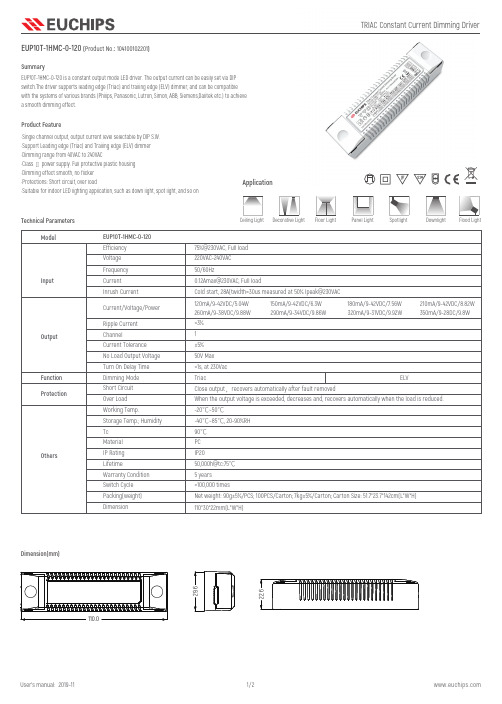
EUP10T-1HMC-0-120 (Product No.: 104100102201)SummaryProduct FeatureDimension(mm)ELV220VAC-240VAC 50/60Hz75%@230VAC, Full load Cold start, 28A(twidth=30us measured at 50% Ipeak@230VAC 0.12Amax@230VAC, Full load110*30*22mm(L*W*H)IP20-20℃~50℃-40℃~85℃, 20-90%RH 90℃PC 50,000h@tc:75℃50V Max ±5%<3%Triac>100,000 times1120mA/9-42VDC/5.04W 260mA/9-38VDC/9.88W 150mA/9-42VDC/6.3W 290mA/9-34VDC/9.86W180mA/9-42VDC/7.56W 320mA/9-31VDC/9.92W210mA/9-42VDC/8.82W 350mA/9-28DC/9.8WEUP10T-1HMC-0-120Tc LifetimeMaterialDimensionNet weight: 90g±5%/PCS; 100PCS/Carton; 7kg±5%/Carton; Carton Size: 51.7*23.7*142cm(L*W*H) Packing(weight)IP Rating Working Temp.Storage Temp.; Humidity Dimming Mode Switch Cycle 5 years Warranty Condition No Load Output Voltage Turn On Delay Time<1s, at 230Vac Efficiency Current Inrush Current Current/Voltage/Power Ripple CurrentChannel Current Tolerance Voltage FrequencyShort Circuit Over Load When the output voltage is exceeded, decreases and, recovers automatically when the load is reduced.Close output ,recovers automatically after fault removedOthersFunction ModelOutputInputProtectionTechnical ParametersApplicationDownlight Panel Light Flood LightSpotlight Ceiling Light Floor Light Decorative Light EUP10T-1HMC-0-120 is a constant output mode LED driver. The output current can be easily set via DIP switch.The driver supports leading edge (Triac) and trailing edge (ELV) dimmer, and can be compatible with the systems of various brands (Philips, Panasonic, Lutron, Simon, ABB, Siemens,Dalitek etc.) to achieve a smooth dimming effect.·Single channel output, output current level selectable by DIP S.W.·Support Leading edge (Triac) and Trailing edge (ELV) dimmer ·Dimming range from 40VAC to 240VAC·Class Ⅱ power supply. Full protective plastic housing ·Dimming effect smooth, no flicker ·Protections: Short circuit, over load·Suitable for indoor LED lighting application, such as down light, spot light, and so onAmbient Temperature(℃)L o a d (%)20406080100120-20-101020304050600Current Selection TableRemark: Function default setting is: 120mA (@switch are all OFF state)Dimming CurveDerating Curve※ The contents of this manual are updated without prior notice. If the function of the product you are using is inconsistent with the instructions, the function of the product shall prevail.Please contact us if you have any questions .L NTRIAC DimmerLampCautions1.The product shall be installed and serviced by a qualified person.2.This product is non-waterproof. Please avoid the sun and rain. When installed outdoors please ensure it is mounted in a water proof enclosure.3.Good heat dissipation will prolong the working life of the controller. Please ensure good ventilation.4.Please check if the output voltage and current of any LED power supplies used comply with the requirement of the product.5.Please ensure that adequate sized cable is used from the controller to the LED lights to carry the current. Please also ensure that the cable is secured tightly in the connector.6.For safety consideration, PVC or rubber cord of 0.75-1.5mm2 is recommended for input and output terminal(s) . Flat power cord is not suitable. Ensure all wire connections and polarities are correct before applying power to avoid any damages to the LED lights.7.If a fault occurs please return the product to your supplier. Do not attempt to fix this product by yourself.00612182430374349556167737985919720406080100120Input (%)O u t p u t (%)EUP10T-1HMC-0-120 (产品代码: 104100102201)概述产品特点EUP10T-1HMC-0-120 是一款可以提供120/150/180/210/260/290/320/350 8档电流的LED 驱动器,输出电流可以通过DIP 拨码开关简易设置,这款驱动器支持前沿切相和后沿切相调光器,可以与多品牌系统(飞利浦,ABB ,路创,西门子,西蒙,松下,邦奇等)配合使用,调光曲线平滑。
- 1、下载文档前请自行甄别文档内容的完整性,平台不提供额外的编辑、内容补充、找答案等附加服务。
- 2、"仅部分预览"的文档,不可在线预览部分如存在完整性等问题,可反馈申请退款(可完整预览的文档不适用该条件!)。
- 3、如文档侵犯您的权益,请联系客服反馈,我们会尽快为您处理(人工客服工作时间:9:00-18:30)。
1
2
3
Reverse Voltage - VR (V)
2007 Semtech Corp.
f = 1 MHz
4
5
Note: Data is taken with a 10x attenuator
3
元器件交易网
PROTECTION PRODUCTS Applications Information
110 100
90 80 70 60 50 40 30 20 10
0 0
Power Derating Curve
25
50
75
100
125
150
Ambient Temperature - TA (oC)
Forward Voltage vs. Forward Current
3
2.5
2
1.5
1
Waveform Parameters:
uClamp1201P
Circuit Diagram
2007 Semtech Corp.
4
元器件交易网
PROTECTION PRODUCTS Applications Information - Spice Model
uClamp1201P
25
20
15
10
Waveform
5
Parameters:
tr = 8µs
td = 20µs
0
0
1
2
3
4
5
6
7
8
9
Peak Pulse Current - IPP (A)
Junction Capacitance vs. Reverse Voltage
Forward Voltage - VF (V)
% of Rated Power or IPP
Ultra-small package (1.0 x 0.6 x 0.5mm) Protects one I/O or power line Low clamping voltage Working voltage: 12V Low leakage current Solid-state silicon-avalanche technology
Circuit Board Layout Recommendations for Suppression of ESD.
Good circuit board layout is critical for the suppression of ESD induced transients. The following guidelines are recommended: z Place the TVS near the input terminals or connec-
Electrical Characteristics (T=25oC)
uClamp1201P
Symbol Ppk Ipp VPP
TJ TSTG
Value 200
8 +/- 20 +/- 15 -55 to +125 -55 to +150
Units Watts Amps
kV
°C °C
Parameter Reverse Stand-Off Voltage Reverse Breakdown Voltage Reverse Leakage Current Forward Voltage Clamping Voltage Clamping Voltage Junction Capacitance
ground loops. z The ESD transient return path to ground should be
kept as short as possible. z Never run critical signals near board edges. z Use ground planes whenever possible.
tr = 8µs
0.5
td = 20µs
0
0
2
4
6
8
10
12
14
Forward Current - IF (A)
ESD Clamping (8kV Contact per IEC 61000-4-2)
CJ(VR) / CJ(VR=0)
1.1 1
0.9 0.8 0.7 0.6 0.5 0.4 0.3 0.2 0.1
PROTECTION PRODUCTS Absolute Maximum Rating
Rating Peak Pulse Power (tp = 8/20µs) Maximum Peak Pulse Current (tp = 8/20µs) ESD per IEC 61000-4-2 (Air) ESD per IEC 61000-4-2 (Contact) Operating Temperature Storage Temperature
Applications
Cellular Handsets & Accessories Personal Digital Assistants (PDAs) Notebooks & Handhelds Portable Instrumentation Digital Cameras Peripherals MP3 Players
15.5 0.100
0.8
Maximum 12 17.5 1
19 25 60
Units V V µA V V V pF
2007 Semtech Corp.
2
元器件交易网
uClamp1201P
PROTECTION PRODUCTS Typical Characteristics
Device Connection Options
These TVS diodes are designed to protect one data, I/O, or power supply line. The device is unidirectional and may be used on lines where the signal polarity is above ground. The cathode band should be placed towards the line that is to be protected.
Mechanical Characteristics
SLP1006P2 package RoHS/WEEE Compliant Nominal Dimensions: 1.0 x 0.6 x 0.50 mm Lead Finish: NiPdAu Molding compound flammability rating: UL 94V-0 Marking: Marking code, cathode band Packaging: Tape and Reel
Non-Repetitive Peak Pulse Power vs. Pulse Time
10
Peak Pulse Power - PPP (kW)
1
0.1
Clamping Voltage - VC (V)
0.01 0.1
1
10
100
Pulse Duration - tp (us)
1000
Clamping Voltage vs. Peak Pulse Current
Dimensions
Schematic & PIN Configura
0.50
Nominal Dimensions (mm)
SLP1006P2 (Bottom View)
Revision 07/31/2007
1
元器件交易网
2007 Semtech Corp.
元器件交易网
PROTECTION PRODUCTS - MicroClampTM
Description
The µClampTM series of TVS arrays are designed to protect sensitive electronics from damage or latch-up due to ESD. It is designed to replace multilayer varistors (MLVs) in portable applications such as cell phones, notebook computers, and PDAs. It features large cross-sectional area junctions for conducting high transient currents. It offers superior electrical characteristics such as lower clamping voltage and no device degradation when compared to MLVs. They offer desirable characteristics for board level protection including fast response time, low operating and clamping voltage, and no device degradation. The µClampTM1201P is in a 2-pin, RoHS/WEEE compliant, SLP1006P2 package. It measures 1.0 x 0.6 x 0.50mm. The leads are spaced at a pitch of 0.65mm and are finished with lead-free NiPdAu. Each device will protect one line operating at 12 volts. It gives the designer the flexibility to protect single lines in applications where arrays are not practical. They may be used to meet the ESD immunity requirements of IEC 610004-2, Level 4 (±15kV air, ±8kV contact discharge). The combination of small size and high ESD surge capability makes them ideal for use in portable applications such as cellular phones, digital cameras, and MP3 players.