3D computational ghost imaging
3D虚幻成像技术探讨

3D虚幻成像技术探讨集成事业部/韩宝杰3D虚幻成像技术起源于Pepper'sghost技术,主要应用于主题公园、游乐场、企业品牌、产品推广展示、展会、视频会议、教学等等场合的应用。
Pepper'sghost是一种虚幻技术,通常在剧院使和一些魔术使用。
使用平板玻璃和特种照明技术,它可以使物体似乎出现或消失,或使一个对象似乎成为另一种“变形”。
一、起源“虚幻成像”最早最著名的成功案例是在1862年,由伦敦皇家理工学院的约翰•亨利•派佩尔(JohnHenryPepper)和工程师亨利•戴瑞克斯(HenryDircks)利用镜子反射投影所做查尔斯•狄更斯(CharlesDickens)的话剧《鬼缠身》(TheHauntedMan)里的鬼出没的效果。
其原理就是利用镜子反射将演员的虚像投影到场景中。
后来这项技术被冠以发明者的名字,就是大家耳熟能详的——派佩尔幽灵“Pepper’sGhost”。
有人也翻译做胡椒鬼,属于望文生义的错误。
JohnHenryPepper鬼缠身它被用来作为对许多魔术,幽灵般的效果的基础上几年,最引人注目的或许是迪士尼乐园鬼屋。
鬼屋二、原理1、基本原理“Pepper'sGhost”源于回到18世纪的中期的HenryDircks和JohnPepper第一次揭示的原则。
它被用来作为对许多幽灵效果的魔术,最引人注目的是迪士尼乐园鬼屋。
最基本原理是,采用一种反射和透射都为50%的镜子,使我们人眼看到的物体图像为二部分物体的图像叠加,一部分透过镜子反射到人眼,另一部分物体通过镜子的虚像传到人眼。
这两部分通过叠加就会产生幻象感觉。
背景应当采用黑色背景,以增加3D图像的立体感。
原理示意图实际效果图2、“鬼屋”原理为了看到幻象,观众必须能够看到到主房间,但看不到隐藏的镜子空间。
玻璃的边缘,可隐藏在地板,通过巧妙设计模式。
这两个房间可以完全相同镜图像,这种方法是使物体出现或消失。
Compressive sensing computational ghost imaging英文精品课件

1
The computational ghost imaging with a phase spatial light modulator (SLM) for wave …eld coding is considered. A transmission mask amplitude object is reconstructed from multiple intensity observations. Compressive techniques are used in order to gain a successful image reconstruction with a number of these observations (measurement experiments) which is smaller that the image size. Maximum likelihood style algorithms are developed, respectively for Poissonian and approximate Gaussian modeling of random observations. A sparse and overcomplete modeling of the object enables the advanced high accuracy and sharp imaging. Numerical experiments demonstrate that an approximative Gaussian distribution with an invariant variance results in the algorithm which is quite simple in implementations and nevertheless e¢ cient for Poissonian observations. c 2012 Optical Society of America
全面详解机器视觉三维成像方法及应用
全面详解机器视觉三维成像方法及应用机器视觉三维成像目前应用最多的光学成像法包括:飞行时间法、激光扫描法、激光投影成像、立体视觉成像等。
飞行时间3D成像飞行时间(TOF)相机每个像素利用光飞行的时间差来获取物体的深度。
目前较成熟的飞行时间面阵相机商业化产品包括Mesa Imaging AG SR-4000, PMD Technologies Cam Cube 3.0,微软Kinect V2等。
TOF成像可用于大视野、远距离、低精度、低成本的3D图像采集,其特点是:检测速度快、视野范围较大、工作距离远、价格便宜,但精度低,易受环境光的干扰。
例如Camcueb3.0可靠的深度精度(<3mm @ 4m),每个像素对应一个3D数据。
扫描3D成像扫描3D成像方法可分为扫描测距、主动三角法、色散共焦法。
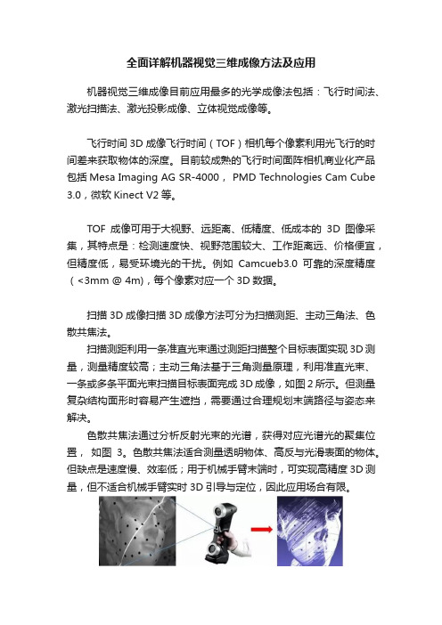
扫描测距利用一条准直光束通过测距扫描整个目标表面实现3D测量,测量精度较高;主动三角法基于三角测量原理,利用准直光束、一条或多条平面光束扫描目标表面完成3D成像,如图2所示。
但测量复杂结构面形时容易产生遮挡,需要通过合理规划末端路径与姿态来解决。
色散共焦法通过分析反射光束的光谱,获得对应光谱光的聚集位置,如图3。
色散共焦法适合测量透明物体、高反与光滑表面的物体。
但缺点是速度慢、效率低;用于机械手臂末端时,可实现高精度3D测量,但不适合机械手臂实时3D引导与定位,因此应用场合有限。
图 2 线结构光扫描三维点云生成示意图图 3 色散共焦扫描三维成像示意图结构光投影3D成像结构光投影三维成像是目前机器3D视觉感知的主要方式。
结构光成像系统是由若干个投影仪和相机组成。
基本工作原理是:投影仪向目标物体投射特定的结构光照明图案,由相机摄取被目标调制后的图像,再通过图像处理和视觉模型求出目标物体的三维信息。
根据结构光投影次数划分,结构光投影三维成像可以分成单次投影3D和多次投影3D方法。
单次投影3D主要采用空间复用编码和频率复用编码形式实现。
Computer-Vision计算机视觉英文ppt

Its mainstream research is divided into three stages:
Stage 1: Research on the visual basic method ,which take the model world as the main object;
Stage 2: Research on visual model ,which is based on the computational theory;
the other is to rebuild the three dimensional object according to the two-dimensional projection images .
History of computer vision
1950s: in this period , statistical pattern recognition is most applied in computer vision , it mainly focuse on the analysis and identification of two-dimensional image,such as: optical character recognition, the surface of the workpiece, the analysis and interpretation of the aerial image.
红外场景仿真系统设计与开发说明书

本科毕业设计说明书(论文)(2017届)论文题目基于Unity3D的红外场景仿真系统设计与开发作者姓名黄可蒙指导教师张繁学科(专业) 软件工程所在学院健行学院提交日期2017年6月摘要随着计算机性能水平的提高以及3D仿真技术的发展,红外成像仿真技术在红外成像系统性能评估,军事模拟训练,灾害救援演习,游戏视觉体验以及其他军事和民用领域具有重要的应用价值。
但是,由于计算机硬件和软件等多方面的条件限制,针对大场景的红外成像仿真系统在适用性和准确性等方面存在较多问题,而其在国防军事的红外制导模拟训练等方面具有重要的应用价值,故此针对大场景,即同时仿真海陆空以及多种地形地貌,针对不同季节时间条件下的仿真系统具有重大意义。
本文通过对红外物理基础理论和自然场景仿真理论的研究,在前人红外成像仿真的研究基础上,整合了海洋陆地红外成像仿真场景,更正修改了部分数学计算模型,使得仿真结果更为精确,同时,利用当下流行的GPU编程语言,通过GPU 编程,对仿真算法进行并行加速计算,在此基础上实现新的红外仿真计算架构:以基于红外特性的物理材质为仿真单位,借助GPU的并行计算能力,在GPU中,对不同场景对象多角度下的红外辐射灰度进行并行计算。
通过该计算框架,可以构建包含多种目标对象的红外场景,包括植被,房屋建筑以及舰船,并且在不低于三十个目标对象的前提下保证仿真系统的实时性。
利用功能强大的Unity3D游戏引擎,完成仿真场景编辑和实现仿真系统的逻辑功能,并实现场景的实时渲染。
通过对重建的三维场景的仿真效果图与实地拍摄的真实的红外场景图像进行比对分析,表明该仿真系统能够高效动态实现多种条件下的较为可信的红外仿真视景。
关键词:红外成像,实时仿真,大场景,计算架构,对比分析ABSTRACTWith the improvement of computer performance and the development of 3D simulation technology, infrared imaging simulation technology has important application value in infrared imaging system performance evaluation, military exercise, disaster rescue exercise, game visual experience and other military and civilian fields. However, due to the limitations of computer hardware and software, the infrared imaging simulation system for large scenes has many problems in applicability and accuracy, and it is important in the infrared guidance simulation training of national defense and military Application value, so for large scenes, that is, at the same time simulation of land, sea and air and a variety of topography, for different season time under the conditions of the simulation system is of great significance.Based on the research of infrared physics basic theory and natural scene simulation theory, this paper integrates the simulation scene of marine terrestrial infrared imaging on the basis of previous research on infrared imaging simulation, and corrects some mathematical calculation models to make the simulation result more accurate. At the same time, using the popular Cg programming language, through the GPU programming, the simulation algorithm is optimized. Thus, a new infrared simulation computing architecture is realized, which can build infrared scenes that contain multiple audiences, including vegetation, housing, and ships, and ensure the real-time performance of the simulation system without less than thirty objects.Utilize the powerful Unity3D game engine to complete the simulation scene editing and realize the logic function of the simulation system and realize the real-time rendering of the scene. By comparing the simulation results of the reconstructed 3D scene with the real infrared scene images recorded in the field, it shows that the simulation system can realize the more reliable infrared simulation scene under various conditions.Key words: infrared imaging, real-time simulation, large scene, computational architecture, comparative analysis.目录摘要 (I)ABSTRACT (II)目录 (III)图目录 (V)表目录 (VI)第一章绪论 (1)1.1 研究工作的背景与意义 (1)1.2 相关工作 (1)1.3 本文的主要贡献与创新 (3)1.4论文组织结构 (4)第二章红外基础物理和数学模型的研究 (5)2.1 引言 (5)2.2 理论背景 (5)2.2.1 辐射的基本概念 (5)2.2.2 红外辐射规律 (5)2.2.3 黑体辐射 (6)2.2.4 傅立叶定律 (7)2.3 零视距离辐射计算模型 (7)2.3.1 自身辐射 (7)2.3.2 反射辐射 (12)2.3.3 热平衡方程 (12)2.4 大气传输模型 (14)2.5 设备仿真模型 (15)2.5.1 成像模糊模型 (15)2.5.2 成像噪声模型 (16)2.6 海洋仿真模型 (17)2.6.1 海面波形仿真 (17)2.6.2 海面折射和反射的仿真 (19)2.6.3 海面浪花仿真 (21)2.6.4 开尔文尾迹仿真 (22)2.7 热源仿真模型 (22)2.7.1 热源设置 (23)2.7.2 效果渲染 (23)2.8 本章总结 (25)第三章相关技术点概述分析 (26)3.1 系统逻辑架构 (26)3.1.1 数据逻辑 (26)3.1.2 系统功能概述 (28)3.2 场景组织 (29)3.2.1 Unity3D功能概述 (29)3.2.2 场景编辑 (30)3.3 场景渲染 (31)3.3.1 渲染流水线 (31)3.3.2 顶点着色器 (33)3.3.3 像素着色器 (34)3.4 本章小结 (34)第四章仿真系统实现和结果分析 (35)4.1 仿真系统实现 (35)4.1.1 算法实现 (35)4.1.2 地形红外仿真 (36)4.1.3 目标对象红外仿真 (39)4.2 仿真结果分析 (39)4.3 真实结果对比 (43)4.4 本章小结 (45)第五章全文总结与展望 (47)5.1 全文总结 (47)5.2 后续工作展望 (48)参考文献 (49)致谢 (52)图目录图2 - 1太阳运动轨迹示意图 (9)图2 - 2光波频率大气透过率分布图 (14)图2 - 3模糊效果总体流程图 (15)图2 - 4模糊效果图 (16)图2 - 5噪声算法流程图 (16)图2 - 6白噪声贴图 (17)图2 - 7噪声效果图 (17)图2 - 8海面波形图 (19)图2 - 9海面折射算法流程图 (19)图2 - 10海面反射算法流程图 (20)图2 - 11海面反射折射效果图 (21)图2 - 12海面浪花效果图 (22)图2 - 13立体相机结构示意图 (23)图2 - 14仿真热源贴图 (24)图2 - 15热源仿真效果图 (25)图3 - 1数据逻辑流程图 (26)图3 - 2系统功能概述图 (28)图3 - 3地形高度效果图 (31)图3 - 4相机视锥体示意图 (32)图4 - 1热平衡方程求解源码示例图 (35)图4 - 2系统实现流程图 (36)图4 - 3地形贴图编辑界面图 (37)图4 - 4地形splat纹理贴图 (37)图4 - 5多材质地形红外仿真效果图 (38)图4 - 6放置热源对象模型效果图 (39)图4 - 7轿车正午红外场景仿真侧视图 (40)图4 - 8轿车午夜红外场景仿真侧视图 (40)图4 - 9轿车午夜红外场景仿真正视图 (41)图4 - 10舰船海面红外尾迹仿真效果图 (41)图4 - 11长时间行驶坦克红外效果图 (42)图4 - 12长时间静止状态坦克红外效果图 (42)图4 - 13向阳面建筑表面红外效果图 (42)图4 - 14深夜0:00时实拍(左)与仿真(右)红外图像对比图 (43)图4 - 15凌晨4:00时实拍(左)与仿真(右)红外图像对比图 (43)图4 - 16早上8:00时实拍(左)与仿真(右)红外图像对比图 (43)图4 - 17正午12:00时实拍(左)与仿真(右)红外图像对比图 (43)图4 - 18傍晚16:00时实拍(左)与仿真(右)红外图像对比图 (44)图4 - 19夜晚20:00时实拍(左)与仿真(右)红外图像对比图 (44)图4 - 20水泥地24小时温度变化仿真实测对比图 (44)图4 - 21草地24小时温度变化仿真实测对比图 (45)图4 - 22车门24小时温度变化仿真实测对比图 (45)表目录表2 - 1风速对照表 (11)表2 - 1风速对照表(续) (12)表2 - 2 MODTRAN不同条件下大气透过率计算值表 (14)表3 - 1红外特性参数表 (26)表3 - 1红外特性参数表(续) (27)第一章绪论1.1 研究工作的背景与意义当物体温度大于绝对零度的时候,物体就会对外产生红外辐射,即向外发射红外电磁波,红外电磁波是电磁波中,波长范围介于可见光波和微波之间的电磁波,波长范围大约是0.76~1000μm。
专业英语3D成像技术应用

090430133李泽辉原文:Volume holographic imaging (VHI) systems incorporate a volume hologram as one of the optical field processing elements in the system.Three dimensional volume imaging has attracted much research interest recently for its wide applications, both in the military areas such as 3D LADAR and the civil areas, e.g. molecular biomedical investigation, on-line industrial product inspection, micro-fabrication investigation, etc. A field with fast growing importance is the 3D volume investigation of the objects that show very fast dynamic changes even in the range of microseconds, e.g. molecular biological process, micro-fabrication process, etc.Generally speaking, hologram is an optical component in which there exists some refractive index modulation. The most common method to make a hologram is to use some photonic-sensitive material to record the interference of two mutually coherent light beams. For example, you may use a silver halide, and let it exposure to the interference fringes of two laser beams. Then you can develop the exposed silver halide to make an amplitude hologram, or you can bleach it to a phase hologram to future improve the diffraction efficiency. Conventionally, people use hologram to record the 3D scene of an object, as you may see in a lot of science museums. Most of these holograms are called thin hologram, namely, their have thin thickness, which is comparable to the wavelength of the light. However, we mainly use volume hologram in our research. Volume hologram typically has a thickness of more dozens of wavelengths. Theories are usually used in treating the optical behavior of the volume holograms are three dimensional scalar diffraction theories or coupled wave theory, up to the strength of the volume hologram. However, the easiest way to understand volume hologram is treating it as a 3D diffractive lattice and applying Bragg diffraction theory.High-quality systems used in video conferencing are called telepresence systems. The images are life-size yet not truly lifelike. They lack the depth that people would normally see if they were in the same room together. But this could change in the future with new kinds of three-dimensional telepresence systems. Researchers can send a moving image over the Internet and show it on a special screen in close to real time. People would not have to wear special glasses like they often need to watch 3-D movies. The system uses a lot of cameras to take pictures of a person from different positions. Lasers reproduce the pictures combined into three-dimensional images, or holograms. The image appears more realistic with the more cameras that are used and the more pictures that are taken.Howard Lichtman is president of the Human Productivity Lab. His company advises other companies on buying and using telepresence systems. Mr. Lichtman also publishes Telepresence Options, which reports on the industry. He says this latest development would have done wonders for the "Star Wars" movie with the famous "Princess Leia" hologram scene. HOWARD LICHTMAN: "For Princess Leia to talk, Princess Leia needs to move and her mouth needs to move, etc. And you haven't been able to do that with a regular hologram because the hologram would only be fixed in one spot. What they're able to do is, they're able to refresh that image so that the image changes the same way a person changes when they talk." The researchers in Arizona say their 3-D system is still years away from completion. Even then, Howard Lichtman says it mayhave trouble competing with systems already on the market. Most telepre HOWARD LICHTMAN: "It's a 2-D image, but it's crystal clear, photo realistic, fluid movement, accurate flesh tones, and you would swear you were in the same physical space with people who might be thousands of miles away."Sence systems are two-dimensional. But Mr. Lichtman says the images are very realistic. He says prices for telepresence systems are going down as more people use the technology. HOWARDLICHTMAN: "It's pushing down to everybody as these environments are becoming publicly available or you can rent them by the hour, and at the same time that you're getting very high quality, high definition video conferencing showing up on mobile devices and in the home delivered through the set-top box or through the PC."Now scientists have invented a gadget that allows viewers to watch three dimensional holographic videoes without the need for special glasses. The breakthrough could revolutionise television, movies and computer games - and see the introduction of 3D advertising billboards on street corners. It could even be used to create three dimensional maps and allow surgeons to perform operations hundreds of miles from patients. The invention, called holographic telepresence, is the brainchild of researchers at the University of Arizona College of Optical Sciences. Dr Nasser Peyghambarian who led the research, said: "This advance brings us a step closer to the ultimate goal of realistic holographic telepresence with high resolution, full colour, human sized, 3D images that can be sent a video refresh rates from one part of the world to another. "Holographic telepresence means we can record a three-dimensional image in one location and show it in another location, in real-time, anywhere in the world." Some images in the movie are recorded using an array of normal cameras, each of which views the object from a different point of view. The information is then encoded onto a fast-pulsed laser beam which interferes with another beam of light, creating an "interference pattern" which is written into the photorefractive material - creating the three dimensional image. The hologram fades away naturally after a couple of seconds or minutes, or it can be erased by recording a new 3D image and storing it on the screen. The prototype refreshes its image every two seconds so movement is jerky and slow. The researchers are working on a 17-inch screen - closer in size to a normal television and say the refresh rate will speed up.Dr Peyghambarian added: "Let"s say I want to give a presentation in New York. All I need is an array of cameras here in my Tucson office and a fast Internet connection. At the other end, in New York, there would be the 3D display using laser system. Everything is fully automated and controlled by computer. As the image signals are transmitted, the lasers inscribe them into the screen and render them into a three-dimensional projection of me speaking."He says the invention could revolutionise home entertainment and be used in "telemedicine".Surgeons at different locations around the world can observe in 3D, in real time, and participate in the surgical procedure. The system currently works in just one colour. However, the scientists have previously developed colour holographic displays that refresh at a faster rate.The last couple of years has seen a revival in 3D movies and television. However, in order to get the 3D effect, viewers have to wear special glasses.The most famous example of "telepresence" in movies appears in the original Star Wars when the droid R2D2 projects a holographic image of Princess Leia delivering a call for help. Earlier this year the electronics company Toshiba unveiled a 3D TV that works without glasses. However, the viewer has to sit close to the screen for the effect to work.翻译:全息成像系统是结合一个作为光学场处理的体全息组件的成像系统。
瑞利分布调制光的反射式关联成像

瑞利分布调制光的反射式关联成像张颖涛; 李洪国【期刊名称】《《实验室研究与探索》》【年(卷),期】2019(038)007【总页数】4页(P16-18,45)【关键词】关联成像; 信噪比; 随机调制光【作者】张颖涛; 李洪国【作者单位】天津理工大学理学院天津300384【正文语种】中文【中图分类】O431.20 引言关联成像又称为鬼成像,是通过强度关联测量获得物体图像信息的一种非直接成像技术。
具体来说是,具有空间关联性质的光源,例如热光源发出的光被分束器分成物光束和参考光束,其中一束光传播一定距离再照射物体后(物光束)被一不具有空间分辨能力的桶探测器接收;另一束光(参考光束)不经过物体,被一具有空间分辨的探测器接收,对上述两探测器记录的信号执行关联测量即可以重建获得物体的关联像。
史砚华等[1]首先利用双光子纠缠光源实现了鬼成像。
随后大量研究表明,利用经典光源例如赝热光源或真热光源也可以实现关联成像[2-14]。
Shapiro等[15]理论上提出了计算关联成像方案,随后Bromberg等[16]实验实现了计算关联成像。
Sun等[17]基于计算关联成像和三维图像重建技术,实验上利用数字光投影仪产生具有二值分布的调制光实现了三维物体的图像重建。
在计算关联成像中,光源可以被调制成具有任意强度概率密度分布的光,在实际中应用更方便[18-20]。
前期的研究主要集中在二值分布或负指数分布[17]。
本文基于瑞利分布的关联成像,首先理论分析强度概率密度函数为瑞利分布的调制光关联成像的信噪比,然后实验上实现基于该分布的反射式物体的计算关联成像。
1 反射式关联成像信噪比理论分析1.1 反射式关联成像信噪比的一般表达式反射式关联成像装置示意图如图1所示,随机调制光源发出的光经分束器变为物光束和参考光路。
其中一束光经过物体反射后(物光束)被一个不具有空间分辨率的桶探测器接收;另一束光(参考光束)自由传播一定距离后被一个具有空间分辨的探测器接收,对上述两探测测得的强度信号进行多次采样执行强度涨落关联测量后即可重建获得反射式物体的图像。
光谱编码计算关联成像技术研究

第50卷第1期V〇1.50No.l红外与激光工程Infrared and Laser Engineering2021年1月Jan.2021光谱编码计算关联成像技术研究黄见A时东锋u,孟文文u,查林彬a孙宇松苑克娥U2,胡顺星a王英俭u(1.中国科学院安徽光学精密机械研究所中国科学院大气光学重点实验室,安徽合肥230031;2.中国科学技术大学,安徽合肥230026)摘要:现有的多光谱成像技术通常采用光学分光的方式,使用多个探测器对成像场景的光谱图像进 行采集,导致现有成像系统复杂,数据量大、效率低。
针对现有技术的不足,提出基于正交调制模式的 光谱编码计算关联成像技术。
通过正交光谱编码矩阵融合Hadamard基图案构造投影散斑对宽带光 源进行调制,单像素探测器收集成像物体与调制光源相互作用后的反射信号;应用演化压缩技术复原 成像物体的混叠光谱图像;利用编码矩阵的正交性质解码出欠采样的光谱分量图像,对分离出的图像 应用组稀疏压缩感知算法重构全采样的光谱分量图像,最后融合出成像物体的多光谱图像。
通过数值 模拟与实验两方面验证了所提方法的高效性。
所提的技术简化了多光谱关联成像系统,降低了数据 量。
光谱编码方法可以扩展到更多的光谱通道,也可以应用在偏振关联成像、信息加密等领域。
关键词:光谱成像;关联成像;压缩感知;压缩压缩技术中图分类号:0431.2 文献标志码:A D O I:10.3788/IRLA20200120Study on spectral encoded computational ghost imagingHuang Jian1,2,Shi Dongfeng1,2,Meng Wenwen1,2,Zha Linbin1,2,Sun Yusong1,2,Yuan Ke'e12,Hu Shunxing1'2,Wang Yingjian1'2(1. K e y Laboratory of Atmospheric Optics, A n h u i Institute of Optics a n d Fine Mechanics,Chinese A c a d e m y of Sciences, Hefei 230031, China;2. University of Science a n d T e c h n o l o g y of China, Hefei 230026, China)Abstract:The existing multispectral imaging technologies usually utilize optical spectroscopy and multiple detectors to capture spectral images.These techniques suffer from complexity,a large amount of data and low efficiency.Addressing these deficiencies,in this paper,a spectral encoded computational ghost imaging technology based on orthogonal modulation model was proposed.The orthogonal spectral encoded matrices fused with Hadamard patterns were used to produce the illumination patterns that modulate the broadband light source.A single-pixel detector was utilized to collect the back-reflected signal from the imaging objects.The evolutionary compressive technology was applied to recover the mixed spectral image.The subsampled spectral channel images were obtained from the mixed spectral image by means of the orthogonality of the spectral encoded matrices.Then the group sparse compressed sensing algorithm was applied to reconstruct the fullsampling spectral channel images,which finally fused the multispectral image of the imaging object.The efficiency of the proposed method was verified by a numerical simulation and an experiment.The proposed收稿日期:2020-04-13;修订日期:2020-04-27基金项目:国家自然科学基金(41505019,41475001);中国科学院青年创新促进会(2020438);先进激光技术安徽省实验室青年 基金(20192201)第1期第50卷technology simplifies the multispectral imaging configuration and greatly reduces the amount of data.The orthogonal spectral encoded strategy can extend to more spectral channels and also can be applied to polarization imaging,information encryption,and other many fields.Key words:spectral imaging;ghost imaging;compressed sensing;evolutionary compressive technology〇引言关联成像作为一种新型的成像技术近年来受到 了国内外广大学者的持续关注。
- 1、下载文档前请自行甄别文档内容的完整性,平台不提供额外的编辑、内容补充、找答案等附加服务。
- 2、"仅部分预览"的文档,不可在线预览部分如存在完整性等问题,可反馈申请退款(可完整预览的文档不适用该条件!)。
- 3、如文档侵犯您的权益,请联系客服反馈,我们会尽快为您处理(人工客服工作时间:9:00-18:30)。
Invited Paper3D computational ghost imagingMatthew P.Edgar a,Baoqing Sun a,Richard Bowman a,b,Stephen S.Welsh a andMiles J.Padgett aa SUPA,School of Physics and Astronomy,University of Glasgow,Glasgow,G128QQ.b Department of Physics,Cavendish Lab,University of Cambridge,Cambridge,CB30HE.ABSTRACTComputational ghost imaging is a technique that enables lensless single-pixel detectors to produce images.By illuminating a scene with a series of patterns from a digital light projector(DLP)and measuring the reflected or transmitted intensity,it is possible to retrieve a two-dimensional(2D)image when using a suitable computer algorithm.An important feature of this approach is that although the light travels from the DLP and is measured by the detector,the images produced reveal that the detector behaves like a source of light and the DLP behaves like a camera.By placing multiple single-pixel detectors in different locations it is possible to obtain multiple ghost images with different shading profiles,which together can be used to accurately calculate the three-dimensional(3D)surface geometry through a photometric stereo techniques.In this work we show that using four photodiodes and a850nm source of illumination,high quality3D images of a large toy soldier can be retrieved.The use of simplified lensless detectors in3D imaging allows different detector materials and architectures to be used whose sensitivity may extend beyond the visible spectrum,at wavelengths where existing camera based technology can become expensive or unsuitable.Keywords:3D imaging,structured illumination,infrared imaging,computational imaging,ghost imaging1.INTRODUCTIONComputational ghost imaging(GI)is an alternative technique to conventional imaging and removes the need for a spatially resolving detector.Instead,ghost imaging infers the scene by correlating the known spatial information of a changing incident lightfield with the reflected(or transmitted)intensity.The principles of GI were originally demonstrated using spatially entangled photon pairs produced by sponta-neous parametric down-conversion,known as quantum GI.1,2The two photons propagate along different paths: in thefirst path,the photon interacts with the object and if not absorbed is detected by a detector with no spatial resolution,in the second path the photon never interacts with the object,but its transverse position is measured by a scanning imaging system.It is by correlating the coincidence measurements over many photon pairs that enables an image of the object to be deduced.It was subsequently demonstrated that GI could be performed not only using an entangled light source but also with thermal light,a technique commonly termed classical GI.3–5In classical GI a copy of the lightfield is usually made with a beam splitter,one copy of the lightfield interacts with the object and a non spatially resolving detector and the other copy is recorded with a camera.Correlations between the two detectors again yield an image,albeit one with a higher background than in the quantum case.6The earlier controversy over the distinction between classical and quantum GI is now largely resolved.7Classical GI systems can be simplified by introducing a device capable of generating computer programmable lightfields,which negates the requirement for the beam splitter and the camera since knowledge of the light field is held in the computer memory.This type of system,termed computational GI,8,9has previously been performed using a programmable spatial light modulator(SLM)and a laser,but can also be achieved using a presentation-type programmable light projector.10,11We note that in this form computational GI is related to Further author information:(Send correspondence to M.P.E.or M.J.P.)M.P.E.:E-mail:matthew.edgar@,Telephone:+44(0)1413306432M.J.P.:E-mail:miles.padgett@,Telephone:+44(0)1413305389Emerging Technologies in Security and Defence; and Quantum Security II; and Unmanned Sensor Systems X,edited by K. L. Lewis, R. C. Hollins, T. J. Merlet, M. T. Gruneisen, M. Dusek, J. G. Rarity, E. M. Carapezza,Proc. of SPIE Vol. 8899, 889902 · © 2013 SPIE · CCC code: 0277-786X/13/$18 · doi: 10.1117/12.2032739single-pixelphotodetector computer light projectorobject analogue-digital converter structured illumination Figure 1.The DLP illuminates the object (toy soldier)with a series of computer generated binary Hadamard patterns.The light reflected from the object is collected on two spatially separated single-pixel photodetectors.The signals from the photodetectors are measured by the computer via the analogue-to-digital converter,and used to reconstruct a ghost image for each photodetector.the field of single-pixel cameras,12the difference being an interchange of the light source and detector,in other words the programmable component is either used to filter the detected light or to structure the illumination.In both single-pixel cameras and GI systems,inverting the known patterns and the measured intensities is a significant computational problem.A number of sophisticated algorithms have been developed over the years to improve the signal-to-noise ratio (SNR)for different GI systems 13,14but with appropriate normalization 15a simple iterative algorithm was adopted for this experiment.All previous GI experiments have been restricted to relatively small 2-dimensional (2D)images,mainly of 2D template objects or 2D outlines of 3-dimensional (3D)objects.In this work we overcome previous limitations of computational GI and capture the 3D spatial form of an object by using several single-pixel detectors in different locations.A spatially identical 2D image is derived from each detector but appears as if it is illuminated from a source located at the detector paring the shading information in the images allows the surface gradient and hence the 3D form of the surface to be reconstructed.2.EXPERIMENTAL SETUPThe experimental setup is shown in Fig.1.The source of structured illumination is a DLP (Texas Instruments Light Commander)that has been modified to use a high-power 850nm wavelength LED for providing near-infrared binary illumination.The light intensity reflected from the scene is measured by two silicon photodiodes (filtered for 850±20nm),located at different positions and directed towards a common point on the object.An analogue-to-digital converter is used to digitize the photodetector signals before they are processed by a computer which is also used to generate the structured illumination.The DLP contains a digital micro-mirror device (DMD),which is a 1024×768array of mirrors (10.8µm pitch)that can each be electronically controlled.The glass panel that protects the DMD is coated for optimum transmission at visible wavelengths,however the device itself has a much wider operational bandwidth (300nm −2µm),enabling the use of this technique at wavelengths potentially unsuitable for existing CCD technology.The illumination structure comprises of binary patterns having an equal black to white ratio,and which are projected onto the scene using a Nikon 50mm focal length lens.For every pattern that is projected a correspond-ing intensity is measured by each photodetector,which is used by the computer algorithm for reconstructing a ghost image.left right top bottomFigure2.The raw images produced from each photodetector located around the object(as indicated)are reconstructed using an iterative algorithm(described in the text).The spatial information in each image is identical;however,the apparent illumination source is determined by the location of the relevant photodetector.DMD-based projectors create colour images by displaying24binary images(bit planes)per frame in quick succession.By alternating between a binary pattern and its inverse in subsequent bit planes we can demodulate the measured signal at the frequency of the bit plane projection(1440Hz)to isolate the back-reflected signal from light sources at other frequencies such as room lighting.Importantly,the fact that the speckle pattern has equal numbers of black and white pixels enables normalization of the measured differential signals for each pattern,which has been shown to improve the SNR of thefinal reconstruction.153.TWO-DIMENSIONAL IMAGE RECONSTRUCTIONBoth iterative and inversion techniques can be applied when reconstructing computational ghost images from a series of M projected binary patterns P(x,y)and measured signals S i.In this experiment we employ an iterative algorithm to avoid storage of large pattern arrays and signals in computer memory.The2D reconstruction of the image I(x,y)is obtained by averaging the product of the(zero-mean)measured signals and patterns,given byI(x,y)=1MMi=1S i P i(x,y),(1)for M iterations.In our earlier work,random binary patterns have been used,however any overlap between patterns inherently introduces redundancy and thus the number of patterns,M,required to form a high-quality N-pixel image can be significantly greater than the Nyquist limit(M>>N).In this work we chose instead to project a complete set of Hadamard patterns,with a resolution set at96×96super-pixels(where1super-pixel is8×8pixels on the DMD).Each Hadamard pattern is orthogonal,and thus a new piece of spatial information is acquired with each iteration,reducing the number of patterns required to M=N.Using1we obtain a separate2D reconstruction of the object(toy soldier with approximate dimensions 25cm×10cm×4cm)for each photodetector,as shown in Fig.2.The ghost images produced with this technique are derived from the same set of patterns projected from a single source at afixed location,thus the spatial information in both images is identical.However,the intensity distribution in each image is different,because the apparent lighting of the object is dependent on the location of the detector used to record the backscat-tered light(a consequence of reciprocity in imaging systems).Therefore,computational ghost imaging has two key differences compared to a camera imaging system:the location of structured illumination determines the perspective and the detector position determines the lighting.4.THREE-DIMENSIONAL IMAGE RECONSTRUCTIONDepth information of a scene is normally lost in a2D image,however one well established technique for the retrieval of3D information,called‘shape from shading’16,17(SFS)uses the shading information in the image caused by geometrical features as an additional degree of freedom from which to infer surface normals.When using only one image the problem is underscontrained since the surface normals represent two degrees of freedom per pixel with respect to the line of sight,and thus many SFS methods make several assumptions,including uniform Lambertian surface reflectance.An extension of this technique called‘photometric stereo’18,19uses multiple images acquired from afixed perspective with different illumination positions,similar to the images acquired form a computational ghost imaging system with multiple single-pixel detectors.For our system we consider that the intensity of a pixel(x,y)in an image obtained from the i th detectorcan be expressed asI i(x,y)=I sαˆdi·ˆn,(2)where I s is the source intensity,αis the surface reflectivity,ˆd i is the unit detector vector pointing from the object to the detector,andˆn is the surface normal unit vector for the object.Thus,for P images,we can write Eq.2asI(x,y)=I sα(D·ˆn),(3) where D is an array containing the unit detector vectors and I(x,y)is an array containing the corresponding image intensities for that pixel.Thus for any pixel(x,y),the unit surface normal isˆn=D−1·I(x,y)I sα,(4)and the surface reflectivity(albedo)isα=|D−1·I(x,y)|.(5) The surface gradient at each pixel can therefore be calculated by evaluating the change between adjacent pixels in the surface normal map,from which3D surface information can be obtained by integration.The integration of surface gradients is performed by starting at the centre of the object and working outwards.The relative surface depth at any pixel is therefore estimated from the height of the neighbouring pixel and the surface gradient.Where more than one nearest neighbour exists,the height is estimated based on the mean of those pixels.A subsequent optimization step is performed on the3D surface,varying the depth of one pixel at a time for each iteration,where the cost function is the sum of the squared differences between the gradients of the reconstructed surface and the gradients recovered from the photometric stereo measurement.This step helps to improve the overall shape and remove spike features that occur at the edge of the3D surface.Our3D computational GI system has been shown to provide accurate3D reconstructions of large surfaces with reasonable geometric complexity,demonstrating a root mean square error of less than4mm.11From the final2D ghost images shown in Fig.2we applied the prescribed method for reconstructing a3D profile of a large toy soldier,shown in Fig.3.5.CONCLUSIONSUtilizing a high power850nm LED as the source of illumination within a commercially available digital light projector,we have demonstrated that large objects can be imaged by lensless single-pixel detectors using compu-tational ghost imaging methods.Our system was capable of projecting a series of orthogonal Hadamard patterns, and processing with an iterative algorithm at a rate of approximately650Hz,from which an image(96×96 pixel resolution)with reasonably high contrast was retrieved after approximately15seconds.This time may be reduced by employing a faster DMD or by reducing the image resolution.Spatially separating four single-pixel detectors is shown to produce ghost images with different shading profiles,determined by their respective po-sitions,thus enabling photometric stereo techniques to be applied for retrieval of3D surface information.ThisFigure3.Rendered views of the3D reconstructed toy soldier derived by integration of the surface normal data and overlaid with the surface reflectivity data.approach,demonstrated at near infrared wavelengths,can be extended for imaging applications at nearly any desired wavelength where light sources and single-pixel detectors exist,potentially in regions where camera based technology is expensive or limited.The deployment of simple,inexpensive,detectors for2D and3D imaging may have importance in various military applications,for example in chemical characterization and or use in hazardous environments.ACKNOWLEDGMENTSThe authors acknowledge the UK Engineering and Physical Sciences Research Council forfinancial support. M.J.P thanks the Royal Society and the Wolfson Foundation.REFERENCES1.Pittman,T.B.,Shih,Y.H.,Strekalov,D.V.,and Sergienko,A.V.,“Optical imaging by means of two-photon quantum entanglement,”Phys.Rev.A52,R3429–R3432(1995).2.Strekalov,D.V.,Sergienko,A.V.,Klyshko,D.N.,and Shih,Y.H.,“Observation of two-photon ghostinterference and diffraction,”Phys.Rev.Lett.74,3600–3603(1995).3.Bennink,R.S.,Bentley,S.J.,and Boyd,R.W.,““two-photon”coincidence imaging with a classical source,”Phys.Rev.Lett.89,113601(2002).4.Gatti,A.,Brambilla,E.,Bache,M.,and Lugiato,L.A.,“Correlated imaging,quantum and classical,”Phys.Rev.A70,013802(2004).5.Valencia,A.,Scarcelli,G.,DAngelo,M.,and Shih,Y.,“Two-photon imaging with thermal light,”Phys.Rev.Lett.94,063601(2005).6.Jack,B.,Leach,J.,Romero,J.,Franke-Arnold,S.,Ritsch-Marte,M.,Barnett,S.M.,,and Padgett,M.J.,“Holographic ghost imaging and the violation of a bell inequality,”Phys.Rev.Lett.103,083602(2009).7.Shapiro,J.H.and Boyd,R.W.,“The physics of ghost imaging,”Quantum Inf.Process11,949(2012).8.Shapiro,J.H.,“Computational ghost imaging,”Phys.Rev.A78,061802(R)(2008).9.Bromberg,Y.,Katz,O.,and Silberberg,Y.,“Ghost imaging with a single detector,”Phys.Rev.A79,053840(2009).10.Sen,P.,Chen,B.,Garg,G.,Marschner,S.R.,Horowitz,M.,Levoy,M.,and Lensch.,H.P.A.,“Dualphotography,”ACM Trans.Graph.24(3),745–755(2005).11.Sun,B.,Edgar,M.P.,Bowman,R.,Vittert,L.E.,Welsh,S.,Bowman,A.,and Padgett,M.J.,“3Dcomputational imaging with single-pixel detectors,”Science340,844–847(2013).12.Duarte,M.F.,Davenport,M.A.,Takhar,D.,Laska,J.N.,Sun,T.,Kelly,K.F.,and Baraniuk,R.G.,“Single-pixel imaging via compressive sampling,”IEEE Signal Process.Mag.25,83(2008).13.Katz,O.,Bromberg,Y.,and Silberberg,Y.,“Compressive ghost imaging,”Appl.Phys.Lett.95,131110(2009).14.Ferri,F.,Magatti,D.,Lugiato,L.A.,and Gatti,A.,“Differential ghost imaging,”Appl.Phys.Lett.104,253603(2010).15.Sun,B.,Welsh,S.S.,Edgar,M.P.,Shapiro,J.H.,and Padgett,M.J.,“Normalized ghost imaging,”Opt.Express20,16892(2012).16.Horn,B.K.P.,“Understanding image intensities,”Artif.Intell.8,201(1977).17.Brooks,M.J.and Horn,B.K.P.,[Shape from shading],MIT Press,Cambridge,MA(1989).18.Woodham,R.J.,“Photometric method for determining surface orientation from multiple images,”Opt.Eng.19,191139(1980).19.Horn,B.K.P.,[Robot Vision],MIT Press,Cambridge,MA(1986).。