FYS-15011CX中文资料
新飞锯说明书中文第4康特飞锯

使用说明书
第4版
1
前言
非常感谢使用 CD 系列飞锯系统! 本使用说明书叙述了 CD 系列飞锯机的安装、运行、维护、保养及检查等项目。在使用前,谨请认真阅读本 使用说明书,同时,请您牢记本产品的安全注意事项。 为保证飞锯系统的长期稳定可靠运行,请用户严格遵照本手册的安装、接线要求。
380V
锯
图五 飞锯的电源与高频、轧机的电源严格分开
18
表三 电线(缆)配置表(电线的线径单位为 mm2)-------适用于直流飞锯
飞锯型号 需总功率 电源线 电枢线 励磁线 锯切电机线 信号线 码盘线
约(KW)
变 电 所 至 控 控 制 柜 至 锯 控 制 柜 至 锯 控制柜至锯切电 控 制 柜 至 各 控制柜至编
CD 系列飞锯控制系统要求电源为三相交流 380V(特殊情况 可依用户定制),电源波动不得大于 10%。
特别提醒用户注意:飞锯控制系统的电源应与高频、轧机的 电源严格分开,布线时也要分开布置。如图五所示。
三相 高
三 相 配 380V 频
低 压 变
电
380V
斯
距离>1 米
三相 380V
轧 机
压 器
三相 飞
测速系统等组成。
CT-01 运动控制器由我公司自主研发,采用国际最先进的 DSP(数字信号处理器)技术。它能高速(1ms)采集
外部信号,并通过复杂的运算,高精度控制执行机构对在线材料的定尺切割。CT-01 运动控制器的图例说明见图一。
10
人机操作界面是液晶触摸屏,通过它可非常方便地修改各种参数,并清晰显示各种实时数据。 CD 系列飞锯控制系统组成框图见图二。 1.1.2 产品应用 CD 系列飞锯控制系统可广泛用于管材、型材等轧制线的高精度连续自动跟踪切割,使生产效率大幅度提高。 1.1.3 技术数据 1) 物料速度:<200m/min*(详细见表一) 2) 速度曲线可在线调整 3) 锯切设定长度:<32m(特殊可定制) 4) 定尺精度:<±3mm (普通锯) ;<±1mm (冲剪锯)** 5) 自动循环工作(包括短尺功能)和手动操作 * 根据飞锯型号及客户要求;
RFL-QCW150 1500 QCW150 准连续光纤激光器中文说明书

RFL-QCW150/1500光纤激光器说明书武汉锐科光纤激光技术股份有限公司Wuhan Raycus Fiber Laser Technologies Co., Ltd.目录1安全信息 (1)1.1安全标识 (1)1.2激光安全等级 (1)1.3安全标识 (1)1.4光学安全 (3)1.5电学安全 (3)1.6其它安全注意事项 (4)2产品介绍 (5)2.1产品特性 (5)2.2装箱清单 (5)2.3开箱及检查 (5)2.4运行环境 (6)2.5注意事项 (7)2.6产品性能 (7)3安装 (8)3.1 整机尺寸图 (8)3.2 输出光缆的尺寸与安装 (10)3.3 冷却系统安装要求 (11)3.4 安装注意事项 (11)4产品的使用 (13)4.1 前面板 (13)4.2 后面板 (13)4.3 电源连接 (14)4.4 接口定义 (14)4.4.1 控制接口 (14)4.4.2 RS-232 串口 (18)4.5 激光器工作模式 (19)4.5.1 子工作模式 (20)4.5.2 控制命令 (21)4.5.2.1 RS-232配置 (21)4.5.2.2 以太网TCP/IP接口 (21)4.5.2.3 控制命令 (22)4.6安装及操作顺序 (27)4.7软件操作 (27)4.8常见故障 (27)5质保及返修、退货流程 (29)5.1 一般保修 (29)5.2 保修的限定性 (29)5.3 技术支持及产品维修 (29)附件A——软件操作说明 (1)A.1 运行环境 (1)A.2 软件安装 (1)A.3 双击运行 (2)A.4 菜单 (2)A.5 主界面功能介绍 (4)A.6 波形编辑 (10)A.7 激光器配置工具 (15)A.8 以太网本地连接配置 (17)1安全信息感谢您选择锐科光纤激光器,本用户手册为您提供了重要的安全、操作、维护及其它方面的信息。
故在使用该产品之前,请先仔细阅读本用户手册。
Z-15GW3-B中文资料(omron)中文数据手册「EasyDatasheet - 矽搜」

• 这些交换机使用一个橡胶套管上情况之间致动器和粘合剂填充和 覆盖,以增加耐滴水.
• 模型与防滴端子防护护盖并用树脂充填模终端也可提供.
分割接触模型
• 这种类型是在结构上不同之处在于它具有两对同时演技触点通过拆 分移动触点通用基本开关相同.
• 由于移动触点被连接到一公共端,并联或串联连接是可能.
2.接 触 间 隙 F:1毫米(大容量)
3.执 行 器
无:引脚柱塞
S: 超薄弹簧柱塞 D: 短弹簧柱塞 Q: 面板安装柱塞 Q22:面板安装滚轮柱塞 W: 铰链杠杆 W22:短铰链滚轮摇臂 W2:铰链滚轮摇臂 M22:反向短铰链滚轮摇臂
4.施 工 Y:
分体式接触式
5.终 端
无:焊接端子
B: 螺丝端子
芯片中文手册,看全文,戳
防滴型号
执行器 引脚柱塞 短弹簧柱塞
弹簧柱塞
面板安装柱塞 面板安装滚轮 柱塞 面板安装交叉 滚轮柱塞 钢板弹簧
滚轮钢板弹簧 短铰链杆 长铰链杆 铰链杠杆 短铰链滚轮摇臂 铰链滚轮摇臂 单向短 铰链滚轮摇臂
反向铰链杠杆* 2
反向短铰链
滚轮摇臂* 2
反向铰链滚轮
• 如果模型被用作双触点开关高度可靠微负载切换得到防护证.
防护持接触模型
• 所维护接触型具有在开关壳体底部有一个复位键,除位于复位按钮 相对侧上按键(柱塞).使用这些按钮交替进行.
• 由于该开关具有比超程更大预行程,很适合 在正反转控制电路中使用,手动复位电路,安全 限制电路,以及其它电路这是不优选 自动复位. (有关详细信息,请参照各 数据表.)
---
---
---
---
---
---
---
---
中文说明书-船舶自动识别系统(AIS)FA-150
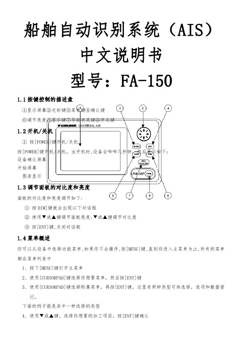
船舶自动识别系统(AIS)中文说明书型号:FA-1501.1按键控制的描述盘①显示屏幕②光标键③菜单键④确认键⑥调节亮度⑤显示键⑦导航状况键⑧开关键1.2开机/关机①按[POWER]键开机/关机按[POWER]键开机/关机。
当开机时,设备会哔哔几秒钟,然后显示如下:设备确认屏幕图表显示1.3调节面板的对比度和亮度面板的对比度和亮度调节如下:①②③1.4都在菜单列表中1、按下[MENU]键打开主菜单2、使用[CURSORPAD]键选择你想要菜单,然后按[ENT]键3、使用[CURSORPAD]键选择附属菜单,再按[ENT]键,这里有两种类型可供选择,选项和数据登记。
下面的例子就是其中一种选择的类型4、使用▼或▲键,选择你想要的加工项目,按[ENT]键确认5、利用附属菜单选择选项或文字数字的数据选择选项下面的例子就是如何从使用者设置菜单中选择选项A、使用▼或▲键选择想要的项目菜单,按[ENT]键确认就会出现以下窗口选择窗口B、按▼或▲键选择你想要的选择按[ENT]键确认输入文字数字的数据A游标BCDE6、按1.512AB3、按NAV4、5符号,和你可以输入20个目的地目的地处理如果您已经登记一些目的地,NAV状态菜单第2页下面如下。
从这个屏幕您能选择,编辑或删除目的地。
当前的目的地目的地清单1)用游标选择适当的目的地,然后按[ENT]键选择,显示窗口如下:2)用游标键选择EDIT或删除,然后按ENT键。
做法如下:选择目的地:按ENT键。
编辑目的地:输入适当编辑目的地;按ENT键。
删除目的地:提示如下出现。
按选择YES,按ENT键。
6、按键就会出现以下菜单7、[DATE]是选项,按下[NET]键8、利用[CURSORAPD]键输入到港时日期并按[ENT]键9、[TIME]是选项,按[ENT]键10、利用[CURSORPAD]键输入到港的预算时间并按[ENT]键1112、1314、153kts或161718191.6123、利用▼或▲键选[CPA/TCPAALARM]并按[ENT]键4、[CPA]是选项,按下[ENT]键5、利用[CURSORPAD]键输入CPA(设置范围:0~6.00NM)并按[ENT]键6、[CPA]是选项;按[[ENT]键7、利用[CURSORPAD]键输入TCPA(设置范围:0~60MIN)并按[ENT]键8、[ALARMMODE]是选项;按下[ENT]键9、选择[ON]使CPA/TCPA警报起作用;[OFF]禁止警报,按[ENT]键10、[ALARMBUZZER]是选项,按下[ENT]键11、选择[ON]使CPA/TCPA内无线电报警,或[OFF]禁止警报,按[ENT]键12、按[DISP]键关闭菜单1.7选择显示目标清单危险(目标)清单当一个危险目标出现时,危险目标用▲▼转换显示内容清单会优先出现本船的静态数据由▲▼显示(详见1.7.4)本船的动态数据(详见1.7.5)报警状态显示选择目标标题本船航行方向路线TCPA1键就会出现描绘显示2、12和3(详见1.7.3)目标类型标志NONE:船■:基本数据▲:SAR:AtoN2、利用▼或▲选择你想看的目标数据并按[ENT]键3、利用▼或▲键显示其他数据“DNGR”危险出现MMSI号码名称呼叫信号IMO号码碰撞距离碰撞时间分别是:MMSI号码、纬度、经度、对地速度、方向(方向精确性H高、L低)、从本船的范围和轴承、轮的率(L左边,R右边)分别是:MMSI号码、从弓到GPS天线位置的距离MMSIMMSI目的地“DNGR”危险出现,当一个目标的CPA分别是MMSI号码、名称、分别是:MMSI号码、纬度、经度、对地速度、方向(方向精确性从船尾到GPS天线位置的距离从口岸到GPS天线位置的距离从右舷到GPS天线位置的距离、船的长度、船射线MMSI号码类型号码类型说明“DNGR”危险出现,当一个目标的CPA和TCPA低于设定的CPA/TCPA分别是:MMSI号码、纬度、经度、对地速度、方向(方向精确性H高、L低)、本船的范围和轴承、轮的率(L左边,R右边)“DNGR”危险出现,当一个目标的CPA和TCPA低于设定的CPA/TCPAMMSICPATCPA分别是:MMSI号码、纬度、经度、对地速度、方向(方向精确性H高、L低)、从本船的范围和轴MMSI名称CPATCPA分别是:MMSI号码、纬度、经度、对地速度、方向(方向精确性承、轮的率分别是:MMSI号码、从弓到GPS天线位置的距离从船尾到从口岸到从右舷到1.731、在描绘显示中,按下[DISP]键显示目标列表(看1.72节)2、按键显示危险列表目标名称碰撞距离、时间按开动TARGETLIST3、想找关于危险目标的详细信息,使用▼或▲键选择目标并按[ENT]键4、利用[CURSORPAD]键改变页▼或▲前进;按▼或▲返回1.74本船静态的数据1、在描绘显示中,按下[DISP]键两次打开[OWNSTATICDATA]项2、利用[CURSORPAD]键打开本船的静态数据;按下▼或▲键前进;▼或▲键返回1.75本船的动态数据显示在描绘显示中,按下[DISP]键三秒打开本船的动态数据日期时间纬度经度当发送时天线会闪动转率RAIM(USE1.81.81123456AIS 7、按89、选择信息类型:NORMAL或SAFETY;按[ENT]键10、选择[CHANNEL],按[ENT]键11、选择你所需要的传输信道发送信息12、按[ENT]键13、按[ENT]键回到[CREATEMSG]附属菜单14、选择[SETMSG]并按[ENT]键可使用、允许的字数量15、利用[CURSORPAD]键输入你的信息,利用▼或▲选择特性,利用▼或▲键移动光标16、按[ENT]键回到[CREATEMSG]附属菜单17、选择[SENDMSG]并按[ENT]键,就会出现以下窗口18、按键[YES]并按[ENT]键发送你的信息1.8.2接收信息如何观看接收到的信息当接收到信息后,就会出现以下窗口:12、按3、选择4、选择N-ABMS-ABNN-BBMS-BBM5、利用6、按在窗口中显示按收到的信息:1、按下[MENU]键打开菜单2、利用[CURSORPAD]键选择[USERSETTINGS]项并按[ENT]键3、利用[CURSORPAD]选择[DISPRCVDMSG]项,并按[ENT]键4、利用[CURSORPAD]键选择你想看的信息并按[ENT]键5、按[DISP]键关闭菜单1.8.3把信息记入航行日志中1、按下[MENU]键打开菜单2、选择[MSG]项按[ENT]键3、选择适当的[TXLOG或RXLOG]并按[ENT]键消息日期和时间发送者的MMSI,信息类型传送、消息状态N-ABM:普通OK:消息地被传送S-ABN:安全FAIL:消息不能被传送N-BBM:普通S-BBM:安全4、选择▼或▲键查看信息的内容,按[ENT]键5、按1.91.9.1123电源频道4、按下[DISP]键关闭显示1.9.2显示,编辑地区操作区域状况:1、按下[MENU]键打开菜单2、选择[CHANNELSETTINGS]并按[ENT]键3、选择[EDITCHANNEL]项并按[ENT]键4、利用▼或▲键从选择号码中选择想要的文件号码5、按下[ENT]键显示详情6、选择[POWER]项,按[ENT]键显示,频道功率选项7、利用▼或▲键选择想要的功率并按[ENT]键8、选择[CHNO。
ICF-1150系列光纤转换器快速安装指南说明书
P/N: 1802011500017 *1802011500017*ICF-1150 Series Quick Installation GuideVersion 8.2, October 2022Technical Support Contact Information/support2022 Moxa Inc. All rights reserved.OverviewIntroductionThe ICF-1150 series of fiber converters has a multi-interface circuit that can handle RS-232 and RS-422/485 serial interfaces, as well as multi-mode or single-mode fiber. ICF-1150 series converters extend serial transmission distance up to 5 km (ICF-1150-M, with multi-mode fiber) or up to 40 km (ICF-1150-S, with single-mode fiber).Why Convert Serial to Fiber?Fiber communication not only extends the communication distance but also provides many helpful features.IMMUNITY FROM ELECTRICAL INTERFERENCE: Fiber is not affected by electromagnetic interference and radio frequency interference. It provides a clean communication path and is immune to cross-talk. INSULATION: Optical fiber is an insulator; the glass fiber eliminates the need for using electric currents as the communications medium. SECURITY: Fiber cannot be tapped by conventional electronic means and is very difficult to tap into optically. Furthermore, radio and satellite communication signals can be captured easily for decoding. RELIABILITY & MAINTENANCE: Fiber is immune to adverse temperature and moisture conditions, does not corrode or lose its signal, and is not affected by short circuits, power surges, or static electricity. Reverse Power ProtectionThe Reverse Power Protection feature provides extra protection against accidentally connecting the power cables to the wrong terminal. The converter detects automatically which power wire is positive and which is negative, and then adjusts the power supply accordingly.3-Way CommunicationThe ICF-1150 series supports 2 serial ports. The D-sub connector is for RS-232 communication and the removable terminal block is for RS-422 or RS-485 communication. The 3 ports (2 serial ports and one fiber port) are completely independent. When the ICF-1150 series converters receive data from any port, it will send data out through the other 2 ports. For example, when the ICF-1150 series converters receive a command from the remote Master via the fiber port, it will convert the command and transmit it via the RS-232 port and RS-422/485 port at the same time. So if the user is trying to monitor a system running on the RS-485 network, there is no need to use an additional RS-232 to RS-485 converter to connect the laptop computer’s serial port to the RS-485 bus.Rotary Switch for Setting the Pull Up/Down ResistorSince the RS-485 port can support multi-drop connections or daisy-chain connections, system engineers can connect meters, RTUs, readers, and many other devices together on the same bus. The impedance of the data line will rise according to the number of serial devices on the same bus. To get the system working, the ICF-1150 has a setting for tuning the pullup/down resistor. Just turn the dial to find the best resistor value for the system withoutremoving the ICF-1150 from the DIN rail. (The default settings are 1k for both switches.)Pull Up/Down ResistorPosition 0 1 2 3 45 6 7 89 Ohms 150k 10k 4.7k 3.3k1k909 822 770 500 485DIP Switch for Selectable TerminatorThe termination resistor for many products of this type is set by a jumper located inside the product’s casing. To disable or change the resistor’s strength, the user must open the casing to reset the jumper. Moxa offers a more user-friendly solution that allows users to set the termination resistor with a DIP switch located outside the ICF-1150 converter’s casing.No Configuration Required for Baudrate SettingsThe ICF-1150 works under any baudrate from 50 bps to 921.6 kbps. The ICF-1150 simply converts the signal back and forth between serial (RS-232, RS-422, or RS-485) and fiber. Since the ICF-1150 does not need to interpret the signal, it does not need to know the baudrate of the transmitting device.NOTE The ICF-1150I default setting is auto baudrate. If you need to use the fixed baudrate, then you will need to use the DIP switch to do the configuration.Ring ModeTo allow one half-duplex serial device to communicate with multiple half-duplex devices connected to a fiber ring, configure the ICF-1150 for “ring mode” by setting DIP switch “SW3” to the “On” position. The Tx port of a particular ICF-1150 unit connects to the neighboring converter’s Rx port to form the ring. Note that when one nodetransmits a signal, the signal travels around the ring until it returns tothe transmitting unit, which then blocks the signal. Users should ensure that the total fiber ring length is less than 100 km when using either single-mode models or multi-mode models.Features•“Ring” or “Point to Point” transmission•Extend RS-232/422/485 transmission distance:up to 40 km with single-mode—ICF-1150-S seriesup to 5 km with multi-mode—ICF-1150-M series•Supports baudrates up to 921.6 kbps•3-way galvanic isolation (for –I models)•Wide operating temperature from -40 to 85°C (for “T” models) •C1D2, ATEX, and IECEx certified for harsh industrial environments Package ChecklistBefore installing the ICF-1150, verify that the package contains the following items:•ICF-1150 fiber converter•Quick installation guide (printed)•Warranty cardNOTE Please notify your sales representative if any of the above items are missing or damaged.Mounting Dimensions (unit: mm)ICF-1150-SCICF-1150-STTop ViewFront ViewATTENTIONElectrostatic Discharge Warning!To protect the product from damage due to electrostaticdischarge, we recommend wearing a grounding device when handling your ICF-1150 product.Mounting (in an enclosure or industrial panel)The aluminum DIN rail attachment plate should be fixed to the back panel of the ICF-1150 when you take it out of the box. If you need to reattach the DIN rail attachment plate to the ICF-1150, make sure the stiff metal spring is situated towards the top, as shown in the figures below.STEP 1: Insert the top of the DIN rail into the slot just below the stiff metal spring. STEP 2: The DIN rail attachment unit will snap into place as shown below.To remove the ICF-1150 series from the DIN rail, simply reverse Steps 1 and 2 above.Pin AssignmentPinRS-2321 –2 TxD3 RxD4 –5 GND6 –7 –8 – 9–Pin RS-422 4-wire RS-485 2-wire RS-4851 GND GND GND2 Rx- Rx- Data -3 Rx + Rx + Data +4 Tx - Tx - –5 Tx + Tx +–Fiber CableSC-Port Pinouts SC-Port to SC-Port Cable WiringST-Port Pinouts ST-Port to ST-Port Cable WiringATEX and IECEx Information1.Certification number:DEMKO 10 ATEX 0917344XIECEx UL 13.0044X2.Ambient range:Model Ambient Temp. RangeModels without suffix“-T”0 to 60°CModels with suffix “T” -40 to 85°C3.Certification string: Ex ec IIC T4 Gc4.Standards covered: EN IEC 60079-0:2018, EN IEC 60079-7: 2015+A1:20185.IEC 60079-0, Edition 7, IEC 60079-7, Edition 5.1Conditions of safeusage:•The Ethernet communication devices must be mounted in a tool-accessible IP54 enclosure in accordance with IEC/EN60079-0 and used in an area of not more than pollutiondegree 2 as defined by IEC/EN 60664-1.•Provisions shall be made to prevent that transientdisturbances should exceed the rated voltage by over 140%.6.The Terminal blocks (J1, J2) are suitable for 14 to 28 AWG(3.31-0.08 mm2), with torque = 1.7 lb-in. The cross-sectional areaof the PE conductor is Sp=3.31 mm2. The conductor used forgrounding is 12 AWG minimum.7.Conductors suitable for use in an ambient temperature of 91°Cmust be used for the power supply terminal.Federal Communications Commission Statement FCC: This device complies with part 15 of the FCC Rules. Operation is subject to the following two conditions:1.This device may not cause harmful interference, and2.This device must accept any interference received, includinginterference that may cause undesired operation.Switch SettingsThere are 4 DIP switches on the front panel of the ICF-1150. Setting Switch 1 Switch 2RS-422 ON OFF2-wire RS-485 OFF ON4-wire RS-485 OFF (default) OFF (default)Fiber Mode Switch 3Ring Mode ONPoint to Point mode OFF (default)120Ω Terminator Switch 4Enable ONDisable OFF (default)The S3 DIP Switch is located inside the ICF-1150. When the ICF-1150 is in RS-485 mode, use this DIP switch to configure RS-485 data direction control, data format, and baudrate. When the ICF-1150 is in RS-232/422 mode, the S3 DIP switch cannot affect RS-232/422 communication.Direction Control and Data Format SettingYou will need to open the product's casing to do the Direction Control and Data Format Setting.NOTE Direction Control and Data Format Setting require the model version v1.2.0 or later.RS-485 Data Direction Control SettingsRS-485 Data Direction Control S3 Pin 1Auto Baudrate OFFFixed Baudrate ONData Format SettingsData Format S3 Pin 2 S3 Pin 3 S3 Pin 47 Bits OFF ON ON8 Bits ON OFF ON9 Bits OFF OFF ON10 Bits ON ON OFF11 Bits OFF ON OFF12 Bits ON OFF OFFThe serial data format includes one start bit, between five and eight data bits, and one stop bit. A parity bit and an additional stop bit might be included in the format as well.For example, 8-N-1 is interpreted as eight data bits, with no parity bit, and one stop bit. Users need to adjust the DIP switch to set the data format to 10 bits.Baudrate S3 Pin 5 S3 Pin 6 S3 Pin 7 S3 Pin 8 S3 Pin 9 50 OFF ON ON ON ON75 ON OFF ON ON ON110 OFF OFF ON ON ON 134.5 ON ON OFF ON ON150 OFF ON OFF ON ON300 ON OFF OFF ON ON600 OFF OFF OFF ON ON1200 ON ON ON OFF ON1800 OFF ON ON OFF ON2400 ON OFF ON OFF ON4800 OFF OFF ON OFF ON7200 ON ON OFF OFF ON9600 OFF ON OFF OFF ON 19200 ON OFF OFF OFF ON 38400 OFF OFF OFF OFF ON 57600 OFF ON ON ON OFF 115200 OFF ON ON ON OFF 230400 ON OFF ON ON OFF 460800 OFF OFF ON ON OFF 921600 ON ON OFF ON OFF LED IndicatorsThere are 3 LEDs on the front panel of the ICF-1150.LED Color FunctionPWR Green Steady ON: Power is ONFiber Tx Green When sending serial data from the fiber port Fiber Rx Yellow When receiving data from the fiber port SpecificationsSerial CommunicationSignals for RS-232 TxD, RxD, SGNDSignals for RS-422 TxD+, TxD-, RxD+, RxD-, SGND Signals for 4-wire RS-485 TxD+, TxD-, RxD+, RxD-, SGND Signals for 2-wire RS-485 Data+, Data-, SGNDBaudrate 50 bps to 921.6 KbpsESD protection 15 kV ESDFiber CommunicationConnector type ST or SCDistance Single-mode fiber for 40 kmMulti-mode fiber for 5 kmSupport Cable Single mode:8.3/125, 8.7/125, 9/125 or 10/125 μmMulti-mode:50/125, 62.5/125, or 100/140 μm Wavelength ICF-1150-S: 1310 nmICF-1150-M: 850 nmTX Output ICF-1150-S: > -8 dBmICF-1150-M: > -8 dBmRX Sensitivity ICF-1150-S: -25 dBmICF-1150-M: -25 dBmPoint-to-Point Transmission Half or Full duplexMulti-drop Transmission Half duplex, fiber ringEnvironmentalOperating Temperature 0 to 60°C (32 to 140°F), 5 to 95 % RH-40 to 85°C (-40 to 185°F) for –T Model Storage Temperature -40 to 85°C (-40 to 185°F), 5 to 95 % RH PowerInput Power Voltage 12 to 48 VDC, 300 mA (Max.) Class 2 Power Line Protection 4 kV Burst (EFT), EN61000-4-44 kV Surge, EN61000-4-5Reverse Power Protection Protects against V+/V- reversalOver Current Protection Protects against 2 signals shortedtogether: 1.1 APower Consumption ICF-1150-S/M-SC/ST: 246 mA @ 12 VICF-1150I-S/M-SC/ST: 300 mA @ 12 V Physical CharacteristicsDimensions (W × D × H) 30.3 × 70 × 115 mmMaterial Aluminum (1 mm)Gross Weight ICF-1150 : 118gICF-1150I : 135gRegulatory ApprovalsCE Class AFCC Part 15 sub Class AEMI EN55032, Class AEMS EN 61000-4-2 (ESD): Contact: 8 kV; Air:15 kV EN 61000-4-3 (RS): 80 MHz to 1GHz: 3 V/mEN 61000-4-4 (EFT): Power: 4 kV;Signal: 1 kV EN 61000-4-5 (Surge):- 11 - Power: 4 kV; Signal: 1 kV EN 61000-4-6 (CS): 150 kHz to 80 MHz: 3 V/m EN 61000-4-8 (PFMF) FreefallIEC 60068-2-32 MTBFICF-1150 : 2,298,766 hrs ICF-1150I : 1,770,450 hrsPay specific attention to the following:1. For indoor use and pollution degree II, wipe with a dry cloth whencleaning up the labeling.2. Please use qualified power supply by SELV or double insulation ofUL60950 or UL61010-1 or UL61010-2-201 standards.3.UL61010-2-201: Shall be mounted in the Industrial Control Panel and the ambient temperature should not exceed 75 degreeCelsius.4. If the equipment is used in a manner not specified by themanufacturer, then the protection provided by the equipment may be impaired.5. We suggest using the cable type 24 AWG (American Wire Gauge)and the corresponding pin type cable terminals.6. We suggest using a torque value of 6.5 lb-in; do not use excessiveforce when fixing wiring.Address of manufacturer: No. 1111, Heping Rd., Bade Dist., Taoyuan City 334004, Taiwan。
横河FLXA21两线制电导率变送器快速启动手册

注1: 安装规范,也称为“过电压类型”,指定瞬时耐受电压。“规程I”(例如两线制变送器)的设备适用于连接到实施测量的回 路以限制瞬时过电压到适当的较低水平。
注2: 污染等级表示固体,液体,气体或其它可能降低绝缘能力的内含物的附着程度。污染等级2是指普通正常室内环境。
2.3.1 接地.................................................................................................................... 7 2.3.2 电源连接 ............................................................................................................ 7 2.3.3 接线盖 ................................................................................................................ 8 2.4 传感器接线 ......................................................................................................................8 2.4.1 pH/ORP传感器接线......................................................................................... 10 2.4.2 电导率(SC)传感器接线.................................................................................... 16 2.4.3 感应式电导率(ISC)传感器接线........................................................................ 17 2.4.4 溶解氧(DO)传感器接线.................................................................................... 18 2.5 安装方法 ........................................................................................................................19
FD5F15CX-E9510中文资料

Edition 1.1 July 2004FEATURES•Direct Modulation Laser for WDM systems•Optimized for Long Distance T ransmission (Dispersion 1800ps/nm)•Peak wavelength 1527.99 to 1563.05nm (C-band:191.8 to 196.2THz, 100GHz spacing)•Output Power:2mW•14-pin Butterfly type package• Built-in Optical Isolator, Power Monitor PIN-PD, Thermistor, and Cooler• Single Mode FiberAPPLICATIONSThis laser is intended for the application of 2.5 Gb/slong haul Dense Wavelength Division Multiplexing (DWDM).T ransmission spans of 100km (1800ps/nm) are possible.DESCRIPTIONThe laser is capable of 2.5 Gb/s transmission.It is packaged in a “butterfly”type module.The module employs a highly stable optical coupling system, coupling the laser output through abuilt-in optical isolator into a single mode fiber pigtail.The module also includes a monitor photodiode, a thermoelectric cooler (TEC), and thermistor.This device is designed for use in DWDM direct modulation transmission systems.Selected wavelengths specified to the ITU-T grid are available.ABSOLUTE MAXIMUM RATINGS (T =25°C, unless otherwise specified)FLD5F15CX-E1,550nm DWDM Direct Modulation DFB LaserFLD5F15CX-EOPTICAL AND ELECTRICAL CHARACTERISTICS (T =T , T =25°C, BOL, unless otherwise specified)Note 1. TE=10*log{pf(Tcase)/Pf(Tc=25°C)}(dB)Note 2. 2.5 Gb/s NRZ, Ppeak=2mW, Rext=8.2dB, PRBS=223-1,Note 3. Bit rate=2.48832 Gb/s, PRBS=223-1, Dispersion=1,800 ps/nm, Ppeak=2mW, Rext=8.2dB Decision point: Center of Back-to-Back at 10-9, No Floor, Receiver: Eudyna Standard ReceiverNote 4. The selected wavelengths available are listed in Fig. 81,550nm DWDM Direct Modulation DFB LaserFLD5F15CX-E(T =T , T =25°C, BOL, unless otherwise specified)Fig. 1 Forward Current vs Output Power Forward Current, If (mA)O u t p u t P o w e r , P f (m W )0132306090Fig. 2 Frequency ResponseFrequency (GHz)R e l a t i v e O u t p u t (d B )630-3-6-9-1291212345P f =2mWT L =25°C1,550nm DWDM Direct Modulation DFB Laser元器件交易网FLD5F15CX-EFig. 4 Cooler Voltage -CurrentCase Temperature (°C)C o o l e r V o l t a g e (V )C o o l e r C u r r e n t (A )-1.03.02.00.01.0-1.03.02.00.01.00203010405060IcVc 7080Fig. 3 RF Return LossFrequency (GHz)R e t u r n L o s s (d B )100-10-20-302030012345Fig. 5 SpectrumWavelength λ (nm)R e l a t i v e I n t e n s i t y (d B )0-10-40-50-60-20-3010154015501560Fig. 6 Temperature Dependance of Wavelength (ACC Operation)Laser Temperature, T L (°C)W a v e l e n g t h (n m )15501551155215531554102030401,550nm DWDM Direct Modulation DFB Laser元器件交易网FLD5F15CX-EFig. 7 Transmission CharacteristicsAverage Input Power (dBm)B i t E r r o r R a t e10-1210-1010-810-610-4Fig. 8 Wavelength TablePart Number FLD5F15CX-E9620-E9610-E9600-E9590-E9580-E9570-E9560-E9550-E9540-E9530-E9520-E9510-E9500-E9490-E9480-E94701527.991528.771529.551530.331531.121531.901532.681533.471534.251535.041535.821536.611537.401538.191538.981539.771540.561541.351542.141542.941543.73±0.1±0.1±0.1±0.1±0.1±0.1±0.1±0.1±0.1±0.1±0.1±0.1±0.1±0.1±0.1±0.1±0.1±0.1±0.1±0.1±0.1Wavelength (nm)(TL=Tset)(in vacuum)Tolerance (nm)-E9460-E9450-E9440-E9430-E94201544.531545.321546.12±0.1±0.1±0.1-E 9410-E 9400-E 9390-E 9380-E 9370-E 9360-E 9350-E 9340-E 9330-E 9320-E 9310-E 9300-E 9290-E 9280-E 9270-E 9260-E 9250-E 9240-E 9230-E 9220-E 9210-E 9200-E 9190-E 91801546.921547.721548.511549.321550.121550.921551.721552.521553.331554.131554.941555.751556.551557.361558.171558.981559.791560.611561.421562.231563.05±0.1±0.1±0.1±0.1±0.1±0.1±0.1±0.1±0.1±0.1±0.1±0.1±0.1±0.1±0.1±0.1±0.1±0.1±0.1±0.1±0.11,550nm DWDM Direct Modulation DFB Laser元器件交易网FLD5F15CX-E1,550nm DWDM Direct Modulation DFB LaserEudyna Devices Inc. products contain gallium arsenide(GaAs) which can be hazardous to the human body and the environment. For safety, observe the following procedures:CAUTION• Do not put this product into the mouth.• Do not alter the form of this product into a gas, powder, or liquidthrough burning, crushing, or chemical processing as these by-products are dangerous to the human body if inhaled, ingested, or swallowed.• Observe government laws and company regulations when discarding this product. This product must be discarded in accordance with methods specified by applicable hazardous waste procedures.For further information please contact:Eudyna Devices USA Inc.2355 Zanker Rd.San Jose, CA 95131-1138, U.S.A.TEL:(408) 232-9500FAX:(408) 428-9111Eudyna Devices Europe Ltd.Network House Norreys DriveMaidenhead, Berkshire SL6 4FJ United KingdomTEL:+44 (0) 1628 504800FAX:+44 (0) 1628 504888Eudyna Devices Asia Pte Ltd.Hong Kong BranchRm.1101, Ocean Centre, 5 Canton Rd.Tsim Sha Tsui, Kowloon, Hong Kong TEL:+852-2377-0227FAX:+852-2377-3921Eudyna Devices Inc.Sales Division1, Kanai-cho, Sakae-kuY okohama, 244-0845, Japan TEL:+81-45-853-8156FAX:+81-45-853-8170Eudyna Devices Inc.reserves the right to change products and specifications without notice.The information does not convey any license under rights of Eudyna Devices Inc.or others.©2004 Eudyna Devices USA Inc.Printed in U.S.A.元器件交易网。
精工SARX001自动机械表 6r15c机芯 中文说明书
目錄
頁
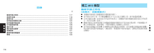
精工 6R15 機型
機械手錶之特性
(自捲式,自動捲動式)
● 本機械手錶利用主發條提供的電能操作運行。 ● 若手錶完全停下來,可手動旋轉錶冠 20 次左右給主發條上弦,使手錶重新啟動。 ● 石英手錶的走慢 / 走快是由月率或年率來表示,而機械手錶的精確度通常是由日率來表 示(每天的走慢 / 走快) 。 ● 機械手錶其正常使用狀態下的精確度根據使用條件的不同亦會出現差異(手錶被戴在手 腕上的時間長短、溫度環境、手臂的移動及主發條的上弦狀況) 。 ● 若手錶受到強磁力的影響, 它會暫時出現走慢或走快現象。若手錶遭受到強磁場的衝擊, 則手錶的某些部件會被磁化。遇此情形,需要排除手錶內的磁性。請與出售此錶的經銷 店聯絡。
5 bar WR
10/15/20
● 防水性能 ● 無防水性能
若錶殼背面上未刻有“WATER RESISTANCE” (防水)字樣,則本錶 不具備防水性能。所以,應特別注意勿將手錶弄濕。因為水可破壞機械 裝置。若手錶被弄濕,建議您把手錶送到出售此錶的經銷店或服務中心 檢測。
bar WR
* 若要在水中使用防水性能 5、10、15 或 20 巴的手錶,應先確認錶冠是否被 完全推入。 勿在手錶被弄濕或處於水中的狀態下操作錶冠。在海水中使用後,要用清水清 洗手錶,並使其完全乾燥。
- 1、下载文档前请自行甄别文档内容的完整性,平台不提供额外的编辑、内容补充、找答案等附加服务。
- 2、"仅部分预览"的文档,不可在线预览部分如存在完整性等问题,可反馈申请退款(可完整预览的文档不适用该条件!)。
- 3、如文档侵犯您的权益,请联系客服反馈,我们会尽快为您处理(人工客服工作时间:9:00-18:30)。
NINGBOFORYARDOPTOELECTRONICSCO.,LTD.LEDDIGITDISPLAY
PartNO.:FYS-15011CX/DX-XX
ADD:NO.115QiXinRoadNingBoZhejiangChinaZIP.:315051TEL:0086-574-8792787087933652FAX:0086-574-87927917Http://www.foryard.comE-mail:sales@foryard.com
DESCRIPTION38.10mm(1.5”)Singledigitnumericdisplayseries.Standardbrightness.Lowcurrentoperation.Excellentcharacterapperance.EasymountingonP.C.boardsorsockets
PackageDimensions&InternalCircuitDiagram
Notes:·Alldimensionsareinmillimeters(inches)·Toleranceis±0.25(0.01")unlessotherwisenoted.·Specificaionsaresubjecttochangewhitoutnotice.
元器件交易网www.cecb2b.comNINGBOFORYARDOPTOELECTRONICSCO.,LTD.LEDDIGITDISPLAY
PartNO.:FYS-15011CX/DX-XX
ADD:NO.115QiXinRoadNingBoZhejiangChinaZIP.:315051TEL:0086-574-8792787087933652FAX:0086-574-87927917Http://www.foryard.comE-mail:sales@foryard.com
:Absolutemaximumratings(Ta=25℃)ValueParameterSymbolTestConditionMinMaxUnit
ReverseVoltageVRIR=30A5-----VForwardCurrentIF-----------30mAPowerDissipationPd-----------100mW
PulseCurrentIpeakDuty=0.1mS,1KHz------150mAOperatingTemperatureTopr------40+85°C
StorageTemperatureTstr------40+85°C
■Description:·ColorCode&Chipcharacteristics:(TestCondition:IF=20mA)ForwardVoltage(VF)Unit:VEmittingColor
Dice
MaterialPeak
WaveLength
(P)
SpectralLine
halfwidth(△1/2)TypMax
LuminousIntensity(Iv)Unit:ucd
HRedGaP/GaP700nm90nm2.252.50500SHiRedGaAlAs/GaAs,SH660nm20nm1.852.203500DSuperRedGaAlAs/GaAs,DH660nm20nm1.852.206000URUltraRedGaAlAs/GaAs,DDH660nm20nm1.852.2012000
EOrangeGaAsP/GaP635nm35nm2.102.502500YYellowGaAsP/GaP585nm35nm2.102.502000GGreenGaP/GaP570nm30nm2.202.502500
·-XX:Surface/Lenscolor:Number012345
RefSurfaceColorWhiteBlackGrayRedGreenEpoxyColorWaterclearWhitediffusedRedDiffusedGreenDiffusedYellowDiffused
元器件交易网www.cecb2b.comNINGBOFORYARDOPTOELECTRONICSCO.,LTD.LEDDIGITDISPLAY
PartNO.:FYS-15011CX/DX-XX
ADD:NO.115QiXinRoadNingBoZhejiangChinaZIP.:315051TEL:0086-574-8792787087933652FAX:0086-574-87927917Http://www.foryard.comE-mail:sales@foryard.com
1.00.503504004505005506006507007508008509009501000
(A)(B)(C)(D)(2)(3)(8)(4)(1)(6)(5)(9)(10)
Wavelength(nm)RELATIVEINTENSITYVsWAVELENGTH()λp
(1)-GaAsP/GaAs655nm/Red(2)-GaP570nm/YellowGreen(3)-GaAsP/GaP585nm/Yellow(4)-GaAsp/GaP635nm/Orange&Hi-EffRed(5)-GaP700nm/BrightRed(6)-GaAlAs/GaAs660nm/SuperRed(8)-GaAsP/GaP610nm/SuperRed(9)-GaAlAs880nm(10)-GaAs/GaAs&GaAlAs/GaAs940nm(A)-GaN/SiC430nm/Blue(B)-InGaN/SiC470nm/Blue(C)-(D)-InGaN/SiC505nm/UltraGreenInGaAl/SiC525nm/UltraGreen
504030201001.21.62.02.42.63.016345284.03.02.01.002040608010015B
5040302010020406080100
162,4,8,A
35
32
1
0.5
0.20.1-30-20-10010203040506070
15423
10987654321110100100010,00010KHz3KHz1KHz300KHz100KHzF-REFRESHRATE100KHz30KHz10KHz3KHz1KHz300Hz100Hz109876
5
43
21110100100010,000
FORWARDVOLTAGE(Vf)FORWARDCURRENTVS.FORWARDVOLTAGERELATIVELUMINOUSINTENSITYVS.FORWARDCURRENTAMBIENTTEMPERATURETa()℃FORWARDCURRENTVS.AMBIENTTEMPERATUREtp-PULSEDURATIONuS(1,2,3,4,6,8,B.D.J.K)NOTE:25freeairtemperatureunlessotherwisespecified℃tp-PULSEDURATIONuSFORWARDCURRENT(mA)FORWARDCURRENT(mA)RELATIVELUMINOUS
INTENSITY
FORWARD
CURRENT(mA)
RELATIVELUMINOUSINTENSITY
AMBIENTTEMPERATURETa()℃(5)
IpeakMAX.IDCMAX.
IpeakMAX.IDC
MAX.
元器件交易网www.cecb2b.comNINGBOFORYARDOPTOELECTRONICSCO.,LTD.LEDDIGITDISPLAY
PartNO.:FYS-15011CX/DX-XX
ADD:NO.115QiXinRoadNingBoZhejiangChinaZIP.:315051TEL:0086-574-8792787087933652FAX:0086-574-87927917Http://www.foryard.comE-mail:sales@foryard.com
PARTNUMBERRANKQ'TYTOTAL
C/NO.5PRODUCT:LEDTYPE:Q'TY:PCSN.W:Kgs
Meas:40.5x30.5x39.5CMG.W:Kgs
PASSEDQC1Q.A:
Date:Quanlity:PartNo:OPTOELECTRONICSPbFORYARDVF:¦ΛD:
tapyQTY/foam(pcs)QTY/Bundle(pcs)QTY/CARTONDimensionFYS-15011C/Dx-xx4*5=2020*16=320320*4=1280
元器件交易网www.cecb2b.com