索尔SOR压力传感器选型资料(中文版)
sor液位开关中文说明书
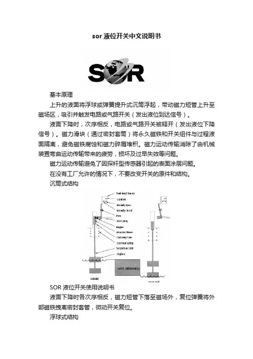
sor液位开关中文说明书基本原理上升的液面将浮球或弹簧提升式沉筒浮起,带动磁力短管上升至磁场区,吸引并触发电路或气路开关(发出液位到达信号)。
液面下降时,次序相反,电路或气路开关被释开(发出液位下降信号)。
磁力滑块(通过密封套筒)将永久磁铁和开关组件与过程液面隔离,避免磁铁腐蚀和磁力碎屑堆积。
磁力运动传输消除了由机械装置弯曲运动传输带来的疲劳,损坏及过早失效等问题。
磁力运动传输避免了因探杆型传感器引起的表面涂层问题。
在没有工厂允许的情况下,不要改变开关的原件和结构。
沉筒式结构SOR液位开关使用说明书液面下降时各次序相反,磁力短管下落至磁场外,复位弹簧将外部磁铁拽离密封套管,微动开关复位。
浮球式结构浮球与一根机械连杆固定在一起,液面上升至浮球,浮力使连杆上升,磁力短管升入密封套筒中,磁力短管的向上运动是在外部永久磁铁产生的磁场内。
磁力把外部磁铁吸向磁力短管,牢固地吸附在密封套管上,此时,微动开关被触发。
液面下降时各次序相反。
磁力短管下落至磁场外,复位弹簧将外部磁铁拽离密封套筒,微动开关复位。
沉筒悬挂在弹簧平衡联动杆上,液面上升时,沉筒的有效重量因受浮力而减小,弹簧回缩拉起连杆,使磁力短管在密封套筒中上升。
磁力短管的向上运动是在外部永久磁铁产生的磁场内,磁力把外部磁铁吸向磁力短管,牢固地吸附在密封套筒上,此时,微动开关被触发。
引压口联接外浮筒接管应当平直且不受干扰,控制头与外浮筒垂直中心线在3℃内。
注意:顶装式控制头与容器法兰或短管安装成与容器的垂直或水平中心线不超过3℃。
(即:外浮筒式与顶装式均应垂直安装)接管长度应控制在最小,以使开关整体更稳定。
如有需要,应采用接管悬挂或支承装置。
控制机构在液体中动作,接管中很可能堆积沉淀物,应采用“T”形或“+”形管接头,允许定期清洗接管。
排污阀及吹扫阀可用于清洁外浮筒和接管。
正常运行中,所有接管上阀门应完全打开,因为限流可能导致误动作。
警告:介质温度超过232℃时,不推荐在外浮筒上使用保温材料。
Sensata Technologies 压力传感器产品简介说明书

Temperature FunctionWORLD CLASSPERFORMANCESensata Technologiesoffers a wide range ofsensing solutions forpressure applications ofevery kind. By focusingour unparalleledengineering and manu-facturing expertise onyour needs, we willmeet the highestexpectations of all -your own.Sensata Technologiesis the world’s leadingsupplier of sensors andcontrols across a broadrange of markets andapplications.WORLD CLASS PERFORMANCE The CP Series’ pressure transducers with their proven ceramiccapacitive technology have been on the market for many years.Our large portfolio with a variety of mechanical and electrical connec-tions creates a broad range of combination possibilities.50.5 (2)73.8 max (2.9)57.9 max (2.3)35.6 max (1.8)ø 24.3 (0.96)8.2 (0.3)3.6 (0.14)40.2 (1.6)30.4 (1.2)Sensata Technologies is the world’s leading supplier of sensors and controls across a broad range of markets and applications.WORLD CLASS 65.0 (2.56)45.6 (1.8)23.9 (0.94)Pressure outputGroundSupply voltageThermistor outputFeatures and benefits• Hermetic pressure sensors with multiple Input/Output options • High accuracy and repeatability • Multiple standard and custom ports • Outstanding EMC performance and high dielectric strengthTypical applications• Air conditioning• Alternative energy management • Compressors and pumps • Hydraulics and pneumatics• Processing control and automation • Vending machinesWORLD CLASS PERFORMANCE The CH Series’ pressure transducers are ideally suited for the most demanding industrial applications. This innovative product is hermetic but not oil-filled and boasts case isolation up to 1800 V.Ground57.2 (2.25)Aø 31.8 (1.25)Power terminalAOuput terminalø 27.4 (1.08)Sensata Technologies is the world’s leading supplier of sensors and controls across a broad range of markets and applications.Technical specificationsWORLD CLASS PERFORMANCE The PP Series’ pressure transducers allow for the best control in an industrial system. A piezo-resistive technology has been selected, whereby the strain gauges are glass fused onto a metal membrane and hermetically sealed.Small Form Factor 30.1 (1.19)ø 13 (0.51)31.7 (1.25)30 m a x (1.18)40 max (1.58)28 (1.10) 26.8 max (1.06)ø 6 (0.24)Sensata Technologies is the world’s leading supplier of sensors and controls across a broad range of markets and applications.WORLD CLASS PERFORMANCE The most accurate technologies for a true Differential Pressure Sensor are Micro-Electro-Mechanical-Systems (MEMS). Our patented MEMSproducts offer the best-value solutions for differential pressure applications.23 (0.9)ø 6 (0.24)23 (0.9)ø 8 (0.32)20 (0.8)71 (2.8)12.6 (0.5)Supply Voltage GroundOutput signal6 (0.24)Sensata Technologies is the world’s leading supplier of sensors and controls across a broad range of markets and applications.Seal material compatibility guideSeal material Media compatibility (please contact Sensata for more information)Maximum seal temperature range*petroleum oils, lubricants, detergent solutionssteam soaps, polar solvents, brake fluid, acetone Skydrol TM chlorinated solvents, oils, fuels, air Pressure connections(please contact Sensata for other connections)27.6 (1.09)Packard Metri-PackAMP MQS - 3 pins 1/4” - 18 NPTF male1/8” - 27 NPTF male1/4” SAE female flare with deflator (7/6” - 20 UNF - 2B)ø 17 (0.67)Electrical connections(please contact Sensata for other connections)16.4 (0.65)23.5 (0.95)34.4 (1.35)DIN 7258519.6 (0.77)ø 23.6 (0.93)12.9 (0.51)26.4 (1.04)34.1 (1.34)3/8” - 24 UNF male1/4” - 19 BSPT male25.1 (0.99)20 (0.79)10.9 (0.43)7 (0.28)14.5 (0.57)24.3 (0.96)9.8 (0.39)14.5 (0.57)8.9 (0.35)VDA13.8 (0.54)27.1 (1.07)7/16” - 20 UNF maleHex 17.5 (0.69)14.6 (0.58)Hex 17.5 (0.69)11.4 (0.45)Hex 15.7 (0.62)9.5 (0.38)M12 x 1 maleM12 x 1.5 maleM14 x 1.5 male13.7 (0.54)16.2 (1.48)11.3 (0.45)10.3 (0.41)9.8 (0.39)M10 x 1.25 female M18 x 1.5 male 10 (0.39)Hex 14 (0.55)12.7 (0.5)14 (0.55)12 (0.47)12 (0.47)6.9 (0.27)13.2 (0.84)12 (0.47)15.5 (0.6)18 (0.71)19.3 (0.76)19.9 (0.78)14.3 (0.56)11.1 (0.44)17.5 (0.69)6.4 (0.25)Hex 15.9 (0.63)12.7 (0.5)9.2 (0.36)Note: Dimensions are shown in mm (inches)Note: Dimensions are shown in mm (inches)10.6 (0.42)12.7 (0.5)15.3 (0.6)10.3 (0.41)Yazaki10.4 (0.41)21.8 (0.96)RD22.3 (0.88)70.1 (2.76)Sensata Technologies Holland B.V. Kolthofsingel 87602 EM ALMELOThe NetherlandsPhone: +31 546 879555Fax:+31 546 870535 Important Notice: Sensata Technologies (Sensata) reserves the right to make changes to or discontinue any product or service identified in this publication without notice. Sensata advises its customers to obtain the latest version of the relevant information to verify, before placing any orders, that the information being relied upon is current. Sensata assumes no responsibility for infringement of assistance or product specifications since Sensata does not possess full access concerning the use or application of customers' products. Sensata also assumes no responsibil-ity for customers' product design.。
SOR压力开关样本
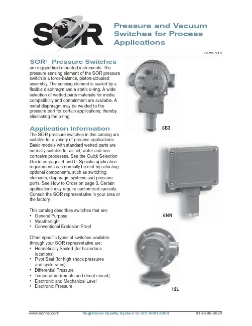
Pressure and Vacuum Switches for Process ApplicationsForm 216SOR ® Pressure Switchesare rugged fi eld-mounted instruments. Thepressure sensing element of the SOR pressure switch is a force-balance, piston-actuated assembly. The sensing element is sealed by a fl exible diaphragm and a static o-ring. A wide selection of wetted parts materials for media compatibility and containment are available. A metal diaphragm may be welded to thepressure port for certain applications, thereby eliminating the o-ring.Application InformationThe SOR pressure switches in this catalog are suitable for a variety of process applications. Basic models with standard wetted parts are normally suitable for air, oil, water and non-corrosive processes. See the Quick Selection Guide on pages 4 and 5. Specifi c application requirements can normally be met by selecting optional components, such as switching elements, diaphragm systems and pressure ports. See How to Order on page 3. Certain applications may require customized specials. Consult the SOR representative in your area or the factory.This catalog describes switches that are: • General Purpose • Weathertight• Conventional Explosion ProofOther specifi c types of switches available through your SOR representative are:• Hermetically Sealed (for hazardous locations)• Pivot Seal (for high shock pressuresand cycle rates)• Differential Pressure• Temperature (remote and direct mount)• Electronic and Mechanical Level • Electronic Pressure12L6B36NNFeatures SwitchesComplete Product LineStandard models and customized specials cover pressure range from30 inches Hg VAC to 4000 psi.Robust ConstructionRugged, high-cycle rate tolerance, long life, not critical to vibration, high overrange and proof pressures, excellent corrosionresistance to hostile environments. Instrument QualityHigh resolution of Set Points, high repeatability, narrow dead band,negligible temperature effect.Wetted PartsWide selection materials, process connection confi gurations and sizes.Optional “fi re-safe” pressure sensor.Snap-Action Electrical SwitchingWide selection UL Listed and CSA Certifi ed switching elements for ACand DC service. Optional “hermeticallysealed” capsule for hazardous and hostile environments.Field AdjustableSelf-locking adjustment, no special tools required. No-charge factory calibration.Cost EffectiveSimple and fast installation without special tools, long service life, norequired periodic service or spareparts.UL Listed, CSA Certifi ed, ATEXCertifi ed, FM, JIS/RIIS Approved ModelsMeets most code and customer requirements.Built-In QualityRigid quality standards maintained from raw material to fi nished product.ServiceFactory sales engineers and area SOR representatives provideeffective and prompt worldwideservice.DeliveryRoutine shipments 7 to 10 working days. Emergency shipments via sameday air.Warranty3 years from date of manufacture.Quick Selection GuideBasic SOR pressure switches with standard wetted parts are normally suitable for air, oil, water and non-corrosive processes. The Quick Selection Guide on pages 4 and 5 shows these basic SOR pressure and vacuum switches. Corrosive service and particular customer requirements may require optional components. Refer to How to Order section below to build a customized model number or the dedicated page to locate optional components, such as switching elements, diaphragm systems, pressure ports and accessories. Each position in the model number, except Accessories, must have a designator.Design and specifi cations are subject to change without notice. For latest revision, see .6NN-K5-M4-C2A-YYModel Number SystemDiaphragmHousingPistonSwitching Element Range SpringPressure PortAccessoriesApplicationsSOR pressure switches in this catalog are suitable for a wide variety of continuous pressure applications. Specifi c application requirements can normally be met by selecting optional components, such as, switching elements, diaphragm systems and pressure ports. Certain applications may require customized specials. Consult the SOR representative in your area or the factory.How to OrderInformation and data in this catalog are formatted to provide a convenient guide to assistinstrument engineers, plant engineers and end users in selecting pressure switches for their unique applications.Steps 1 through 5 are required. Step 6 is optional. Orders must have complete Model Numbers, i.e. each component must have a designator.Step 1: Select Piston-Spring adjustable range/Set Point from Specifi cations (pages 7 & 8). (Piston/Spring combination determines adjustable range.)Step 2: Select Housing for type of pressure switch and service (page 9).Step 3: Select electrical Switching Element for electrical service (pages 10 & 11).Step 4: Select Diaphragm and O-Ring for process compatibility and containment (pages 12 & 13).Step 5:Select Pressure Port for process compatibility and connection (page 14).Step 6: Select Accessories required for service (page 16).How to OrderSwitchesExplosion ProofWeathertightBasic SOR pressure switches with standard wetted parts are normally suitable for air, oil, waterand non-corrosive processes. Corrosive service and particular customer requirements may require optional components. Refer to How to Order on page 3 to locate optional components, such as, housing, switching elements, diaphragm systems, pressure ports and accessories. Each position in the model number, except Accessories, must have a designator.WeathertightExplosion ProofStandard Construction• Housing: NN - aluminum; L - cast iron• Switching Element: SPDT; N - 10 amps @ 250 VAC; K - 15 amps @ 250 VAC• Diaphragm & O-ring: N4 - primary (wetted)diaphragm, TCP; o-ring (wetted) Buna-N• Pressure Port: 1/4” NPT(F); B1A - aluminum; F1A - carbon steelNotes1. See balance of catalog for construction options.2. Dead band values are expressed as typical expected at mid-range for a particular model number. See Dead Band Considerations on page 8.3. Design and specifi cations subject to changewithout notice. For latest revision, see.Standard Construction• Housing: NN - aluminum; L - cast iron• Switching Element: SPDT; K - 15 amps @ 250 VAC• Diaphragm & O-ring: N4 - primary (wetted)diaphragm, TCP; o-ring (wetted) Buna-N• Pressure Port: 1/4” NPT(F); B1A - aluminum; F1A - carbon steelNotes1. See balance of catalog for construction options.2. Dead band values are expressed as typical expected at mid-range for a particular model number. See Dead Band Considerations on page 8.3. Design and specifi cations subject to change without notice. For latest revision, see .WeathertightExplosion ProofExplosion ProofWeathertightStandard Construction• Housing: NN - aluminum; L - cast iron• Switching Element: SPDT; K - 15 amps @ 250 VAC • Diaphragm & O-ring: N4 - primary (wetted) diaphragm, TCP; o-ring (wetted) Buna-N. Piston 56 primary (wetted) diaphragm, 316SS.• Pressure Port: 1/4” NPT(F); B1A - aluminum; F1A - carbon steelNotes1. See balance of catalog for construction options.2. Dead band values are expressed as typical expected at mid-range for a particular model number. See Dead Band Considerations on page 8.3. Design and specifi cations subject to change without notice. For latest revision, see .Quick Selection Guide - VacuumPressure SwitchA bi-stable electromechanical device that actuates/deactuates one or more electrical switching element(s) at a predetermined discrete pressure/vacuum (Set Point) upon rising or falling pressure/vacuum.Adjustable RangeThe span of pressure between upper and lower limits within which the pressure switch can be adjusted to actuate/deactuate. It is expressed for increasing pressure.Set PointThat discrete pressure at which the pressure switch is adjusted to actuate/deactuate on rising or falling pressure. It must fall within the adjustable range and be called out as increasing or decreasing pressure.Dead BandThe difference in pressure between theincreasing Set Point and the decreasing Set Point. It is expressed as typical, which is an average with the increasing Set Point at mid-range for a pressure switch with the standard K switching element. It is normally fi xed (non-adjustable).Fire-SafeThe ability of a welded seal pressure sensor to contain the process at elevated temperatures up to 1200°F at the rated overrange pressure, unsupported by the body of the pressure switch.Hermetically SealedA welded steel capsule with glass-to-metal, factory-sealed electrical leads that isolates the electrical switching element(s) from the environment.OverrangeThe maximum input pressure that can be continuously applied to the pressure switch without causing permanent change of Set Point, leakage or material failure.SwitchesGlossary of T ermsSOR recognizes that there is no industry convention with respect to terminology and defi nitions pertinent to pressure switches. This glossary applies to SOR pressure switches.Proof PressureThe maximum input pressure that can be continuously applied to the pressure switch without causing leakage or catastrophic material failure. Permanent change of Set Points may occur, or the device may be rendered inoperative.RepeatabilityThe ability of a pressure switch to successively operate at a Set Point that is approached from a starting point in the same direction and returns to the starting point over three consecutive cycles to establish a pressure profi le.Repeatability on SOR switches will be smaller than 1% of full scale per ISA/ANSI S51.1. SPDT Switching ElementSingle-Pole, Double Throw (SPDT) has three connections: C — Common, NO — Normally Open and NC — Normally Closed, whichallows the switching element to be electrically connected to the circuit in either NO or NC state.DPDT Switching ElementDPDT is two synchronized SPDT switching elements which actuate together at increasing Set Point and deactuate together at decreasing Set Point. Discrete SPDT switching elements allow two independent circuits to be switched; i.e., one AC and one DC.The synchronization linkage is factory set, and is not fi eld adjustable. Synchronization is verifi ed by connecting test lamps to the switching elements and observing them go “On” simultaneously at actuation and “Off” simultaneously at deactuation.6NN-K5-M4-C2A-YY This table is a listing of piston-spring combinations and the corresponding adjustable ranges, dead bands, overrange and proof pressures. Adjustable range is expressed for increasing pressure; the Set Point must be within the adjustable range. Dead band is expressed as typical. See Dead Band Considerations on page 8.1. Dead band values are expressed as typicalexpected at mid-range with the standard Kswitching element assembly installed. Whenoptional switching elements are specifi ed,corresponding dead band multipliers shownon pages 8 and 10 must be applied.2. The 12/66 piston/spring combination isavailable with the N switching element only.3. Adjustable range becomes 10 to 45 in. wcwhenever switching elements other than K, KA,W or D are used.4. Special ranges may be possible. Consult thefactory or the SOR representative in your area. 5. Diaphragms may have an additional effect ondead band. See page 13, Note 9.6. Diaphragm life may be limited by using T or Hswitching elements with Numbers 1 and9pistons.7. Metric bar (mbar) values are practicalequivalents of the reference English values; notnecessarily exact mathematical conversions.This data appears on the product nameplatewhen metric engineering units are specifi ed.8. A breather drain (Accessory KK, see page 16)should be specifi ed when low pressureadjustable ranges are used in environmentswith signifi cant ambient temperature changes.9. Filled isolators attached to the pressure switchwill affect dead band.This table is a listing of piston–spring combinations and the corresponding adjustable ranges, dead bands, overrange and proof pressures. SOR vacuum switches are compound; they will operate in either vacuum or pressure modes. Adjustable range is expressed from maximum vacuum decreasing to zero gauge andincreasing to maximum pressure. Dead band is expressed as typical. See dead band considerations below. The Set Point must be within the adjustable range. A vacuum switch is generally better suited than a pressure switch for Set Points very near zero gauge.Notes1. Dead band values are expressed as typical expected at mid-range with the standard K switching element assembly installed. When optional switching elements are specifi ed, corresponding dead band multipliers shown below must be applied.2. Special ranges may be possible. Consult the factory or the SOR representative in your area.3. Diaphragms may have an additional effect on dead band. See page 13, Note 9.4. Metric bar (mbar) values are practical equivalents of the reference English values; not necessarily exact mathematical conversions. This data appears on the product nameplate when metric engineering units are specifi ed.1. Dead band values are expressed as typical expected atmid-adjustable range using the standard K switching element. When optional switching elements are specifi ed, corresponding dead band multipliers must be applied.2. Dead bands are fi xed (non-adjustable), except when T or H switching elements are used.3. Dead band can be adjustable by selecting T or H switching element. (Diaphragm life may be limited when used with Numbers 1 and 9 pistons.)4. Dead band multipliers must be applied to the typical dead band value shown for piston-spring combination in specifi cations, pages 7 and 8, whenever optional switching elements other than K, KA or W are used.5. Dead band can be widened by selecting an optional switching element with a multiplier greater than 1.0. Example: Model 6NN-G5-M4-C2A-YY Typical Dead Band 1.4 psi G-Switching Element multiplier = 3 Corrected Typical Dead Band 1.4 x 3 = 4.2 psi6. See item #9, page7.Dead Band Considerations52NN-K 116-M4-C2A-YYClass II, Group E, F, & G; Divisions 1 *L*S*LC*T A*J4NNN6P3Electrical: 3/4” NPT(F) - Left, Right Material: AluminumSee Agency Listings pages 17 & 18.See Switching Element Groups 1, 2, 3 & 4 below.N3N4RN RBSwitchesStep 2: Housing*BD only available with RN, RT housings.*C micro switch is not available in L, S and TA housings.*CA micro switch only available in PP, NN, N3 and N4 housings.Switches Step 3: Switching Element6NN-K5-M4-C2A-YYCross reference compatibility chart on page 9 to ensure that switching element will fi t in housing. Review notes on page 11 for more details.SwitchesStep 3: Switching Element6NN-K 5-M4-C2A-YYNotes1. Double switching elements have wire leads except when supplied in housings RB, RM, RN, RS, RT, B3, B4, B5, B6 and J4. Terminal blocks are standard in these housings.2. Dead band multipliers must be applied to thetypical dead band fi gures given in the specifi cation tables on pages 7 and 8.3. Switching element ambient temperature limits:-65 to 400o F (-54 to 200o C) B, Y, W-65 to 250o F (-54 to 120oC) A, E, & J-40 to 167o F (-40 to 75oC) AF, AG, E F , EG,JF, JG-13 to 158o F (-25 to 70o C) BD-65 to 180o F (-54 to 80o C) All others4. The hermetically sealed switching elementcapsule is ATEX Approved, UL Listed, CSA Certifi ed and SAA Approved as an explosion-proof snap switch according to the following table with conditions and exceptions specifi ed in Note 3.5. Switching elements W, & Y have Elgiloy springs.6. Certain switching elements can handle greater voltage and/or amperage. Consult the factory should your requirements exceed catalog values. All switching elements above except BD are UL Recognized and CSA Certifi ed. The DC current ratings marked with an asterisk (*) are not UL Listed but have been verifi ed by testing and/or experience.7. Ambient temperature is reduced to 200°F (93°C) for J, JJ, A, AA, E, EE, B, BB, Y, YY, & W switching elements when CV accessory is selected.CAUTION: The switching element assemblyhas been precisely positioned in the housing at the factory for optimum performance. Any inadvertent movement or replacement in the fi eld will degrade performance, could render the device inoperative, and can void the warranty unless factory authorized proceduresare followed.Notes Array1. N4 diaphragm system is standard, but requiresa designator in the model number. It is normallysuitable for air, oil, water and noncorrosiveprocesses. M2 diaphragm system is standardon Number 56 vacuum switches. (See notes10 & 13.)2. U7 designates a welded fl ush-type diaphragm.Available only in 1” NPT(M) 316SS onNumbers 5 & 6 pistons with K switchingelement. See page 15.3. U8 designates the welded fi re-safe diaphragmsystem. 316SS is stocked. Not available onNumber 1 piston or vacuum switches.Example: U8-C2A is a 316SS fi re-safe weldeddiaphragm system. See page 15.4. U9 designates a welded diaphragm system.Not available on vacuum switches.Example: U9-A1A is a Monel weldeddiaphragm system. See page 15.5. Other diaphragm and o-ring combinations maybe available. Consult the factory or the SORrepresentative in your area for more information.6. Wetted parts have been selected asrepresenting the most suitable commerciallyavailable material for use in the service intended.However, they do not constitute a guaranteeagainst corrosion or permeation, since processes vary from plant to plant and concentration ofharmful fl uids, gases or solids vary from time totime in a given process. Empirical experienceby users should be the fi nal guide. Alternatematerials are generally available.(Continued on page 13.)7. N3 diaphragm system utilizes a durableback-up diaphragm for high cycle-rate, highshock applications where Buna-N and TCP are compatible with the process. Consult factory if process temperatures are well below freezing.8. This table shows allowable minimum andmaximum temperatures for o-rings. Consult the factory for temperatures down to –65°F onfi re- safe and welded metal diaphragmsystems.9. Dead bands are slightly higher when usingH, J, N3, N6, U or W series diaphragmoptions. Consult the factory.10. Diaphragm systems N1, N3, N4, N5, N6, N7,N8, P1, R1, S1, S2, W2, W4, W5, W6, Y1,U8, U9 are not available on Number 56vacuumswitches.11. M9 diaphragm system is suggested for steamapplications up to 400°F.12. If Kalrez, EPR or Viton is selected for hightemperature process media or ambienttemperature requirements, the A, B, E, J, W or Y switching elements are suggested withreference to the table in Note 3, page 11. 13. Only diaphragm systems N1, N4, N5, N7, N8and P1 are available on the 12-66 piston-springcombination.SwitchesStep 5: Pressure Port6NN-K5-M4-C2A -YYNotes1. Select designators for material and connection size. Large bold-face letters denote those items generally available from stock. Small light-face letters denote items with limited stock and possible long delivery.2. 1/4” and 1/2” tapered BSP(F) pressure ports are available. Consult factory.3. Combinations are possible when a particular connection size is not available for the range (piston/spring) desired. For example, if 2” NPT(F) is desired for a Number 4 piston, the Number 12 pressure port can be supplied. The piston would be designated as Number 124 and the overrange and proof pressures for Number 12 apply. Note: 124, 125 and 126 are the only available combinations.4. Many other materials such as PVC, Kynar, etc., are available. Denote materials not shown by specifying an X followed by the required connection size, and describe the material.Examples:X2A = PVC pressure port with 1/2” NPT(F) connection.X1A = Titanium pressure port with 1/4” NPT(F) connection.Non-metal pressure ports generally reduce proof pressure and may reduce overrange pressure. The pressure port material may limit the process temperature. Delivery may be longer than normal.5. Raised-face and fl at-face fl anges to match ASA 150 and ASA 300 lb. in commercially available materials can be supplied on Series 12 and 4 pistons by adding an X suffi x to the model numbers and specifying “X - (size) inch (material) (raised- or fl at-) face fl ange to match ASA (rating) lb.”6. Brass not available on Piston Numbers 9 and 1.7. 1/4” NPT(F) Flushing Port standard on C6A pressure ports.*C4A only available with Pistons 5 & 6 when U7 diaphragm is specifi ed. See page 15.See next page for presentation of welded diaphragm and FM Approved fire-safe systems.Pressure and Vacuum SwitchesWelded Diaphragm & Fire-Safe SystemsFactory Mutual System Approved - U.S Patent Number 4,438,305Two-inch Pressure PortThe wide pressure port minimizes the possibility of clogging when the process media is sludgy or viscous. See page 20 for dimensions. A 2” NPT(F) pressure port with a 1/4” NPT(F) fl ushing port can be supplied with a welded diaphragm, or with a conventional diaphragm and o-ring combination.ConnectionPiston ShaftDiaphragmSwitches Step 6: Accessories6NN-K5-M4-C2A-YY*Consult the factory for materials other than 316/316L.CSATIISATEXBASEEFASOR Pressure Switches in this catalog may be specifi ed with manual reset electrical switching elements D or M. D actuates automatically on increasing pressure. M actuates automatically on decreasing pressure. Depress the button to manually reset. Housings must be RB (weathertight) or S (explosion proof) because of the requirement of a hub for the manual reset assembly. Refer to page 3 for How to Order instructions.Shipping WeightsManual Reset ButtonRB - Weathertight S - Explosion ProofSwitchesManual ResetActual shipping weights may vary from the charted values because of product material, confi guration and packaging requirements.NotePK Pipe Kit adds approximately 1.5 lbs. (0.7 kgs). TB Junction box adds approximately 5 lbs (2.25 kgs).Dimensions in this catalog are for reference only. They may be changed without notice. Contact the factory for certifi ed drawings for a particular model number.Notes 1. Dimensions in this catalog are expressed as millimeters over inches (Linear = mm/in.). 2. Dimensions marked with an asterisk (*) on housing dimension drawings (pages 20 through 31) vary with respect to process connection size. The chart below lists these dimension variances. 3. Electrical Connection Size: 3/4” NPT(F) standard. 1/2” NPT(F), 1/2” NPT(M), M20 x 1.5, PG 13.5, PF 3/4” optional. Consult the factory for compatibility with selected housing or agencylisting.DimensionsSwitchesDimensionsDimensions in this catalog are for reference only. They may be changed without notice. Contact the factory for certifi ed drawings for a particular model number.Wide Pressure Port: C6ASee description on page 15.Pipe Mounting Kit: PKDrawing # 0091354Drawing # 0090300Drawing # 0091353Junction Box with T erminalBlock:TBDimensions in this catalog are for reference only. They may be changed without notice. Contact the factory for certifi ed drawings for a particular model number.Weathertight - NEMA 4, 4X, IP65Housing PP, P3 and PF are General Purpose.(Cover gasket is not installed.)Dimensions in this catalog are for reference only. They may be changed without notice. Contact the factory for certifi ed drawings for a particular model number.Piston Numbers 5, 6, 1, 9, 56Dimensions in this catalog are for reference only. They may be changed without notice. Contact the factory for certifi ed drawings for a particular model number.Open BracketDesignators: H3Piston Numbers 5, 6, 9, 1, 56Drawing # 0090027Dimensions in this catalog are for reference only. They may be changed without notice. Contact the factory for certifi ed drawings for a particular model number.Weathertight - NEMA 4, 4X, IP65Designators: N6Piston Numbers Drawing 0090020Dimensions in this catalog are for reference only. They may be changed without notice. Contact the factory for certifi ed drawings for a particular model number.Conventional Explosion ProofDimensions in this catalog are for reference only. They may be changed without notice. Contact the factory for certifi ed drawings for a particular model number.Conventional Explosion ProofDesignators: SPiston Numbers 5, 6, 9, 1, 56Drawing # 0090147Dimensions in this catalog are for reference only. They may be changed without notice. Contact the factory for certifi ed drawings for a particular model number.Conventional Explosion ProofPiston Numbers 5, 6, 9, 1, 56SC shown. LC identical except right-handelectrical connection only.Dimensions in this catalog are for reference only. They may be changed without notice. Contact the factory for certifi ed drawings for a particular model number.Conventional Explosion ProofPiston Numbers 5, 6, 9, 1, 56Dimensions in this catalog are for reference only. They may be changed without notice. Contact the factory for certifi ed drawings for a particular model number.Explosion ProofDimensions in this catalog are for reference only. They may be changed without notice. Contact the factory for certifi ed drawings for a particular model number.Weathertight - NEMA 4, 4X, IP65Drawing # 0090271Designators: RB Manual ResetPiston Numbers 5, 6, 1, 9, 56Pressure and VacuumSwitches Dimensions Dimensions in this catalog are for reference only. They may be changed without notice. Contact the factory for certifi ed drawings for a particular model number.Conventional Explosion ProofDrawing # 0090169Designators: S Manual ResetPiston Numbers 5, 6, 1, 9, 56*Refer to Dimensions table on page 19 for changes in length due to process connection size, including A dimension.Registered Quality System to ISO 9001:200032/32Form 913-888-2630echOsonix Level TransmittersT emperature SwitchesP r e s s u r eFlowLevelLevel SwitchesFlow SwitchesPressure SwitchesSOR ®offers a full line of commercial-grade process instruments.TemperatureRegistered Quality System to ISO 9001:2000Form 216 (04.08) ©2008 SOR Inc.We Deliver Quality On TimeSOR Europe, Ltd.Star RoadPartridge Green, Sussex RH13 8RA, United Kingdom Phone +44-140-371-1331Fax +44-140-371-0177sales@SOR - ChinaRoom 903, No. 10 Building Wan Da PlazaNo. 93 Jian Guo Road Chao Yang District Beijing, China 100022Phone +86 (10) 5820 8767Fax +86 (10) 5820 8770SOR Inc.14685 West 105th Street Lenexa, Kansas 66215Phone 913-888-2630Toll Free 800-676-6794Fax 913-888-0767Process Instrumentation。
压力传感器SA-1001-002规格书说明书
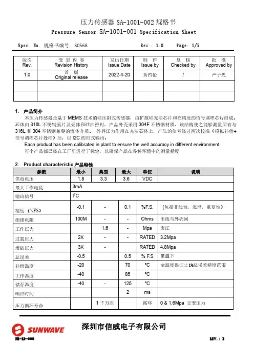
Spec.No.规格书编号:S0568Rev.:1.0Page:1/5深圳市信威电子有限公司版次Rev.变更内容Revision History发出日期Issue Date 制作Issue by 复核Checked by批准Approved by 1.0首版Original release2022-4-20黄哲伦/严子光1.产品简介本压力传感器是基于MEMS 技术的硅压阻式传感器,由扩散硅充油芯片和高精度的信号调理芯片组成。
芯体由316L 不锈钢膜片及壳体和硅油密封,产品外壳采用304F 不锈钢材质,该结构使之能够测量所有与316L 和304不锈钢兼容的流体介质。
外界压力作用在充油芯体上,产生的信号经过两次校准(模拟补偿+信号调理芯片处理)后,以I2C 的形式输出。
Each product has been calibrated in plant to ensure the well accuracy in different environment 每个产品都已经在工厂里进行了标定,以确保产品在各种环境中的测量精度Spec.No.规格书编号:S0568Rev.:1.0Page:2/5深圳市信威电子有限公司3.输出接口及管脚定义注:1.产品的内部电路已经在I2C 总线上放置了4.7K 的上拉电阻2.所有管脚与产品的金属外壳之间是绝缘的4.产品外形结构(单位:mm )5.功能描述5.1.工作模式传感器的默认工作模式为:产品上电后,进入到休眠状态,仅在接收到相应的I2C 命令后才会启动一次压力和温度的测量动作,之后再次自动进入休眠状态,以节省功耗。
5.2.上电启动及休眠唤醒当电源电压小于0.2V 时,传感器处于复位状态,在电源电压以最低10V/ms 的上升速率经过1ms 的延迟后,I2C 接口处于正常状态,可以接受主机命令,在经过2.5ms 的延迟后,传感器可以进行正常的压力和温度测量。
当传感器处于休眠状态时,在接收到主机命令后的0.5ms 时间内从休眠状态进入到工作模式,详细请参Spec.No.规格书编号:S0568Rev.:1.0Page:3/5深圳市信威电子有限公司照上电时序图6.I2C 接口6.1.I2C 接口电气特性在产品内部,I2C 总线的时钟信号线和数据线已经具有4.7k 的上拉电阻6.2.I2C 通讯速率本传感器的I2C 接口可工作于标准模式(100Kbit/s )、快速模式(400Kbit/s)、和高速模式(3.4Mbit/s)。
Endress+Hauser 电导力探头 型号:11371 技术信息书说明书
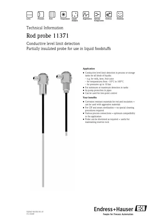
TI276F/00/EN/05.1071115349Technical InformationRod probe 11371Conductive level limit detectionPartially insulated probe for use in liquid foodstuffsApplication•Conductive level limit detection in process or storage tanks for all kinds of liquids:– e.g. for milk, beer, fruit juice– for temperatures from –10°C to 100°C – for pressures up to 10 bar•For minimum or maximum detection in tanks •As pump protection in pipes•Can be used for two-point control Your benefits•Corrosion resistant materials for rod and insulation = can be used with aggressive materials•For CIP and steam sterilisation = no special cleaning procedures required•Various process connections = optimum compatibility to the application•Probe can be shortened as required = useful for maintaining reserves tockRod probe 11371Function and system designMeasuring principle An electrically conductive connection is made between the probe and vessel wall as soon as material in thevessel is in contact with the tip of the probe.Modularity•Probe 11371 in vessels containing liquid.•Nivotester FTW325 conductive level limit switch in the control room.Signal processing•The probe in contact with the material causes avery low current to flow.•The Nivotester FTW325 amplifies the signal and activates any switching devices connected.Galvanic isolation In the Nivotester FTW325.Mechanical constructionDesign, Dimensions•Rod probe, diameter 8 mm, length 50 mm to 2000 mm•Process connection: welded or threaded boss G½ A,•Housing as hex-nut 41AF•Weight: see product structure →ä3•Electrical connection: Two terminals for wires with spade terminalsLeft: with welded boss, right: with threaded boss, Length of partial insulation: 20 mm shorter than the probe length, max.180 mmMounting Caution!•Steam sterilisation may split the insulation of the probe rod if the surface is scratched. Care should be takento protect the insulation when transporting, shortening and mounting the probe.•When mounting the probe, there should be sufficient space out side the vessel so that it can be inserted intoit without using force.•Before welding: unscrew the boss from the housing and remove the rod.•When screwing in: screw the housing in as far as possible into the welded or threaded boss.If the cable gland is not in the correct position after the probe has been screwed in, it can be exchanged withthe stop on the otherside.2Endress+HauserRod probe 11371Endress+Hauser 3Electrical connectioncentral terminal for the probe rod; side terminal for ground connectionTerminals in the housing are for wires with spade terminals for M4 screws.The M16 cable gland is designed for cable diameters from 5.5 mm to 10 mm.Ordering informationRod probe 11371!Note!Please state probe length in mm when ordering. Probe length is always measured from the lower edge of the process connection.Technical DataApplication Limit detection: Maximum or minimum detection in vessels with liquid, conductive food stuffs.Input•Measured variable: Height (limit value, binary)•Measuring range (detection range): Length specified by vertically mounted probe (50 to 2000 mm from above). Specified by installation point when probe mounted horizontally.Output•Probe: current, supplied by Nivotester.•Nivotester FTW325: See Technical Information.MountingAt any orientation; vertical from above preferred; probe length up to approx. 500 mm when mounted from the side, tip of sensor points slightly downwards for liquid to run off and prevent build-up of material.10Approval1Non-hazardous area20Process ConnectionBasic weight 1)1Weld-in socket 30 mm0.59 kg 2Thread ISO 228 G1/2, 316 Ti 0.53 kg 3w/o process flange connection 2)0.41 kg9Special version30Probe lengthAdditional weight1..... mm L, 316 Ti + PFA 0.04 kg/dm 2200 mm L, 316 Ti + PFA 0.08 kg 3500 mm L, 316 Ti + PFA 0.20 kg9Special version995Marking1Tagging (TAG)11371Product designation1) Basic weight: Complete probe without stated length 2) For installation in apre-mounted welding neck adapterAmbient conditions•Ambient temperature and ambient temperature range: –20°C to +120°C (0°F to 250°F)Note temperature resistance of connecting cable!•Storage temperature: –20°C to +120°C (0°F…250°F)•Ingress protection: With cable gland M16 x 1,5: IP66/ IP68 (1m, 1h) to EN 60529•Electromagnetic compatibility (EMC): Interference immunity and interference emission: see Nivotester FTW325 limit switchProcess conditionsMaterialsOrdering information•Probe 11371: see ordering information →ä3•Welded boss (for probe "without process connection") Order No. 517211-1000•Supplementary documentation: Technical Information on the Nivotester FTW325 limit switch on request•Process temperature (operating temperature T Β): –10°C to +100°C (10°F to 210°F)•Process temperature limit: +150°C (300°F)(cleaning temperature, max. 30 min)•Process pressure (operating pressure p e ): –1 bar to +10bar (–14.5 psi to +150 psi)•Maximum process pressure: 10 bar (150 psi)•Conductivity of liquid: min. 0.02 mS/cm, seeNivotester FTW325 limit switchpart materialprobe rod stainless steel 1.4571 (AISI 316 Ti)welded boss threaded boss housing partial insulation0,2 mm PFA, sinter-fused gasket in process connection siliconecable gland M16brass, nickel-plated, with silicone gasketInstruments InternationalEndress+HauserInstruments International AG Kaegenstrasse 24153 Reinach SwitzerlandTel.+41 61 715 81 00Fax +41 61 715 25 ***************.comTI276F/00/EN/05.1071115349CCS/FM+SGML 6.071115349。
NEXON压力传感器选型手册
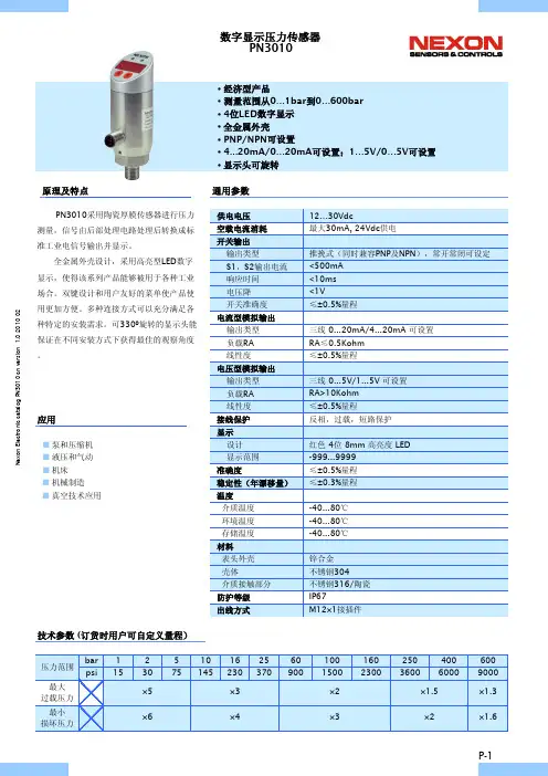
原理及特点通用参数应用■泵和压缩机■液压和气动■机床■机械制造■真空技术应用技术参数 (订货时用户可自定义量程)PN3010采用陶瓷厚膜传感器进行压力测量,信号由后部处理电路处理后转换成标准工业电信号输出并显示。
全金属外壳设计,采用高亮型LED 数字显示,使得该系列产品能够被用于各种工业场合。
双键设计和用户友好的菜单使产品使用更加方便。
多种连接方式可以充分满足各种特定的安装需求。
可330º旋转的显示头能保证在不同安装方式下获得最佳的观察角度。
·经济型产品·测量范围从0…1bar 到0…600bar ·4位LED 数字显示·全金属外壳·PNP/NPN 可设置·4...20mA/0…20mA 可设置;1…5V/0…5V 可设置·显示头可旋转N e x o n E l e c t r o n i c c a t a l o g P N 3010 c n v e r s i o n 1.0 2010 02设定面板窗口模式窗口模式下降过程中压力值要小于rP1时开关输出才释放。
窗口功能可使产品用来监视压力值是否超出一个特定的压力范围。
当压力值在rP1和SP1之间时,开关输出一种状态,而当压力值处于这个范围之外时开关输出另一种状态(与前一种相反)。
选型表i特殊要求可订制■用户指定的压力范围■G1/2, NPT1/2过程连接■食品卫生级法兰连接■用于粘性介质的齐平膜安装方式■加装用于高温介质的散热器■用户提出的其它电气,机械连接N e x o n E l e c t r o n i c c a t a l o g P N 3010 c n v e r s i o n 1.0 2010 02原理及特点通用参数应用■工程机械■液压和气动■机床■机械制造■泵和压缩机■石油钻探量程相关参数 (订货时用户可自定义量程)PN3020采用不锈钢薄膜传感器进行压力测量,信号由后部处理电路处理后转换成标准工业电信号输出并显示。
SOR液位开关使用说明书
SOR液位开关使用说明书SOR液位开关使用说明书工作原理上升的液面将浮球或弹簧提升式沉筒浮起,带动磁力短管上升至磁场区,吸引并触发电路或气路开关(发出液位到达信号)。
液面下降时,次序相反,电路或气路开关被释开(发出液位下降信号)。
磁力滑块(通过密封套筒)将永久磁铁和开关组件与过程液面隔离,避免磁铁腐蚀和磁力碎屑堆积。
磁力运动传输消除了由机械装置弯曲运动传输带来的疲劳,损坏及过早失效等问题。
磁力运动传输避免了因探杆型传感器引起的表面涂层问题。
在没有工厂允许的情况下,不要改变开关的原件和结构。
沉筒式结构SOR液位开关使用说明书沉筒悬挂在弹簧平衡联动杆上,液面上升时,沉筒的有效重量因受浮力而减小,弹簧回缩拉起连杆,使磁力短管在密封套筒中上升。
磁力短管的向上运动是在外部永久磁铁产生的磁场内,磁力把外部磁铁吸向磁力短管,牢固地吸附在密封套筒上,此时,微动开关被触发。
最新的信息可以登陆查询通过ISO9001认证液面下降时各次序相反,磁力短管下落至磁场外,复位弹簧将外部磁铁拽离密封套管,微动开关复位。
浮球式结构引压口联接外浮筒接管应当平直且不受干扰,控制头与外浮筒垂直中心线在3℃内。
注意:顶装式控制头与容器法兰或短管安装成与容器的垂直或水平中心线不超过3℃。
(即:外浮筒式与顶装式均应垂直安装)接管长度应控制在最小,以使开关整体更稳定。
如有需要,应采用接管悬挂或支承装置。
控制机构在液体中动作,接管中很可能堆积沉淀物,应采用“T”形或“+”形管接头,允许定期清洗接管。
排污阀及吹扫阀可用于清洁外浮筒和接管。
正常运行中,所有接管上阀门应完全打开,因为限流可能导致误动作。
警告:介质温度超过232℃时,不推荐在外浮筒上使用保温材料。
电气接线警告:在开启开关外壳之前,一定要保证电源已经被断开。
忘记断开电源可能会导致严重个人伤害或巨大的财产损毁。
请确认接线以及接线的联接符合所有当地和国际电气规范。
外壳上的电气接口可旋转360°,只需松开外壳底座的定位螺钉即可。
菲索AFRISO压力传感器
菲索AFRISO压力传感器压力传感器是工业实践中最为常用的一种传感器,其广泛应用于各种工业自控环境,涉及水利水电、铁路交通、智能建筑、生产自控、航空航天、军工、石化、油井、电力、船舶、机床、管道等众多行业,下面就简单介绍一些常用传感器原理及其应用。
另有医用压力传感器。
彪贺(上海)仪器仪表有限公司,是一家集研发、生产、销售为一体的压力传感器厂家,公司专业研制和生产传感器、变送器、自动化仪器仪表、工业控制系统,也可以根据客户的需求提供专业化的开发和测试解决方案。
为确保我们的产品和技术服务的有效性、规范化和流程化,确保最大限度的顾客满意度,我们严格按照ISO9000 质量保证体系来实现公司内部的严密管理程序和顾客端的灵活优化服务水平.中文名称压力传感器外文名称Pressure sensor输出信号4-20ma、0-10V等基本简介压力传感器是工业实践中最为常用的一种传感器,一般普通压力传感器的输出为模拟信号,模拟信号是指信息参数在给定范围内表现为连续的信号。
或在一段连续的时间间隔内,其代表信息的特征量可以在任意瞬间呈现为任意数值的信号。
而我们通常使用的压力传感器主要是利用压电效应制造而成的,这样的传感器也称为压电传感器。
我们知道,晶体是各向异性的,非晶体是各向同性的。
某些晶体介质,当沿着一定方向受到机械力作用发生变形时,就产生了极化效应;当机械力撤掉之后,又会重新回到不带电的状态,也就是受到压力的时候,某些晶体可能产生出电的效应,这就是所谓的极化效应。
科学家就是根据这个效应研制出了压力传感器。
压电传感器中主要使用的压电材料包括有石英、酒石酸钾钠和磷酸二氢胺。
其中石英(二氧化硅)是一种天然晶体,压电效应就是在这种晶体中发现的,在一定的温度范围之内,压电性质一直存在,但温度超过这个范围之后,压电性质完全消失(这个高温就是所谓的“居里点”)。
由于随着应力的变化电场变化微小(也就说压电系数比较低),所以石英逐渐被其他的压电晶体所替代。
索尔SOR压力传感器选型资料(中文版)
聆听机械微米级专业的判断一个帕斯卡的反应,我们也会告诉您我们一直在努力追求微帕自控的力量SOR索尔压力开关SOR公司(中文名称索尔公司)成立于1946年,是世界上唯一一家集生产各类机械及电子压力、差压、温度、流量、液位开关及变送器于一体的专业化国际公司,总部位于美国肯萨斯州州府,现有员工300人,其压力开关类产品产量位居世界第一。
压力开关产品主要采用静态O型圈密封的活塞-弹簧-膜片组合式结构,具有抗震、抗过压能力强,测量范围广且回差小、使用寿命长等特点。
其生产的高静压低差压开关是世界上独一无二的。
其核级压力及差压开关是世界上不多的取得IEEE认证的产品。
SOR的机械液位开关全部满足ANSIB31.1和B31.3国际电力和石化行业压力容器标准,包括机械式浮球及沉筒两类,其独特的分级冷凝球降温措施能够很好地保证液位开关的开关单元部分免受高温蒸汽的影响,可以可靠地应用于高温工况,越来越受到客户的青睐。
除机械类产品外,SOR的电子产品种类也是非常丰富的,包括热差式流量开关、非接触式超声波变送器、接触式超声波开关,射频导纳开关及变送器、以及集开关、变送器、实时显示三位一体的SGT,该仪表不仅有实时压力显示、独立的开关量输出,而且有4~20毫安模拟量输出。
非接触式超声波变送器具有高能量、低频率、自动增益调节三大特点使其能够应用于诸如碳黑、干灰、啤酒、石膏等高粉尘、高泡沫及高雾气的复杂环境中,帮助很多用户解决了多年来用其他超声波产品甚至是雷达产品都解决不了的难题。
压力控制器(压力计)NN²最大工作压力30 inHg 到 7000 psig ²0.25mm活塞行程,使用寿命长²设定点可调²10amps@250VAC²CSA, CE²NEMA 4, 4X, IP65RN ²最大工作压力30 inHg 到 7000 psig ²0.25mm活塞行程,使用寿命长²设定点可调²10amps@250VAC>²CSA, CE NEMA 4, 4X, IP65L ²最大工作压力30 inHg 到 7000 psig²0.25mm活塞行程,使用寿命长²设定点可调²10amps@250VAC²CSA, CE UL: Class I, Group C, Div. 1B3²最大工作压力30 inHg 到 7000 psig²0.25mm活塞行程,使用寿命长²设定点可调²10amps@250VAC²CSA, CE UL/CSA: Class I, Group B, Div. 1; ATEX: Eex d IIC T6V1²双设定点²最大工作压力30 inHg 到 4000 psig ²0.25mm活塞行程,使用寿命长²设定点可调²10amps@250VAC CSA, CEV2²双设定点²最大工作压力30 inHg 到 4000 psig²0.25mm活塞行程,使用寿命长²设定点可调²10amps@250VAC UL/CSA: Class I, Group A, Div. 1; SnapSw: UL/CSA, ATEX, SAA差压控制器(差压计)101NN,121NN ²最高工作压力从 3 到500 psig²设定点可调²可适用于系统静压突变的工况²15amps@250VAC²CSA, CE ²NEMA 4, 4X, IP65101RN,121RN ²最高工作压力从 3 到500 psig²设定点可调²系统最大静压为1000 psig²可适用于系统静压突变的工况²15amps@250VAC²CSA, CE²NEMA 4, 4X, IP65101L,121L ²最高工作压力从 3 到500 psig²设定点可调²系统最大静压为1000 psig²可适用于系统静压突变的工况²15amps@250VAC²CSA, CE²UL: Class I, Group C, Div. 1101B3,121B3²最高工作压力从 3 到500 psig²设定点可调²系统最大静压为1000 psig²可适用于系统静压突变的工况²15amps@250VAC²CSA, CE²UL/CSA: Class I, Group B, Div. 1; ATEX: Eex d IIC T6101AG,121AG ²最高工作压力从 3 到500 psig²设定点可调²系统最大静压为1000 psig²可适用于系统静压突变的工况²15amps@250VAC²CSA, CE ²UL/CSA: Class I, Group A, Div. 1; ATEX: Eex d IIC; SnapSw:UL/CSA, ATEX, SAARB²最高工作压力从 0.5 到1000 psig²设定点可调 r²可适用于系统静压突变的工况²CSA, CES ²最高工作压力从 0.5 到500 psig²设定点可调²可适用于系统静压突变的工况²UL: Class I, Group C, Div. 1102W1,103W1²设定点可调²最高工作压力从 7 inwc 到2500 psig²系统最大静压为3000 psig²不锈钢外壳²CSA, CE|液位控制器(液位计)100 系列,741-743,801,802²高温环境,温度从 -65°F 到 1000°F²最大工作压力为128bar²控制器单元为不锈钢或者高温陶瓷,抗高温、抗腐蚀²干净/含有杂质液体²最小额定电流为3A@ 220VAC²全系列为ANSI/ASME 标准²所有材质通过ASTM 等级的材料认证 ²UL, CSA, ATEX, SAA ²带腔体侧装200 系列,740-803²高温环境,温度从 -65°F 到 1000°F²最大工作压力为690bar²控制器单元为不锈钢或者高温陶瓷,抗高温、抗腐蚀²干净/含有杂质液体²最小额定电流为3A@ 220VAC²全系列为ANSI/ASME 标准 ²所有材质通过ASTM 等级的材料认证²UL, CSA, ATEX, SAA²带腔体侧装700 系列,730-750²高温环境,温度从 -65°F 到 1000°F²最大工作压力为128bar²控制器单元为不锈钢或者高温陶瓷,抗高温、抗腐蚀²干净/含有杂质液体²全系列为ANSI/ASME 标准²所有材质通过ASTM 等级的材料认证²UL, CSA, ATEX, SAA 顶装300系列²高温环境,温度从 -65°F 到 1000°F²最大工作压力为128bar²控制器单元为不锈钢或者高温陶瓷,抗高温、抗腐蚀²干净/含有杂质液体²全系列为ANSI/ASME 标准²所有材质通过ASTM 等级的材料认证²UL, CSA, ATEX, SAA 顶装108, 208 系列²高温环境,温度从 -65°F 到 1000°F²最大工作压力为690bar²控制器单元为不锈钢或者高温陶瓷,抗高温、抗腐蚀²干净/含有杂质液体²最小额定电流为3A@ 220VAC²全系列为ANSI/ASME 标准 ²所有材质通过ASTM 等级的材料认证²UL, CSA, ATEX, SAA 带腔体侧装1500 系列,1710²最大工作压力为1500 psi, 温度从 -40°F 到 400°F²所有材质通过ASTM 等级的材料认证²CSA温度控制器(温度计)NN ²工作温度从 -50° 到 1000° F²设定点可调²整体安装或分体安装²可选316SS 材质保护套管²316SS 材质探头 ²CSA, CERN²工作温度从-50° 到 1000° F²设定点可调²整体安装或分体安装²316SS 材质保护套管连接²316SS 材质探头 ²CSA, CEL ²工作温度从 -50° 到 1000° F²设定点可调²整体安装或分体安装²316SS 材质保护套管连接²316SS 材质探头 ²UL: Class I, Group C, Div. 1B3²工作温度从 -50° 到 1000° F²设定点可调²整体安装或分体安装²316SS 材质保护套管连接²316SS 材质探头 ²UL/CSA: Class I, Group B, Div. 1; ATEX: EEx d IIC射频导纳651单点RF 控制器²可用作报警器或指示器²不受探头上的工艺物料挂料的影响²经济性好的单点式检测仪表²可用于12VDC 供电²经FM (工厂互助保险公司)认证,并经CSA (加拿大标准协会)认证和CENELEC (欧洲电工技术标准化委员会)认证可应用于危险性工作地点²可在现场选择的故障自动保护功能²环境温度范围-40~71℃²重复精度0.5%²外壳防护等级NEMA 4X 和IP65681单点RF 控制器(具备自检功能)²提供单点控制器功能²通过连续性的自我测试(自检)对开关的运行进行检查。
SOR压力开关(中文)
压力开关产品主要采用静态O型圈密封的活塞膜片式结构,具有抗震、抗过压能力强,测量范围广泛且回差小,使用寿命长等特点。
其生产的高静压低压差开关是世界上独一无二的。
其核极压力产品也是世界上唯一取得IEEE 认证的产品。
·控制范围从负压力1kg/cm2到680kg/cm2,分多级控制;
·控制压力最大为680kg/cm2
·微压控制为15mm水柱
·真空-0-压力控制为:1kg/cm2(负压)-0-5.5kg/cm2
·双设置点压力开关可以独立控制两点不同的压力值
·切换差分可调与不可调两种
SOR公司(中文名称索尔公司)成立于1946年,是世界上唯一一家集生产各类机械及电子压力、差压、温度、流量、液位开关及变送器于一体的专业化国际公司,其压力开关类产品产量位居世界第一.
美国SOR公司主要产品为压力、差压、温度、流量及液位开关,所有产品全部采用ISO9001质量标准,分普通型和防爆型两大类产品,产品的主要认证机构有:美国UL、加拿大CSA、澳大利亚ASS、日本的JIS、欧洲CENELEC等。
SOR公司的开关量仪表主要采用膜片活塞式结构,有耐高压、高温、防震、防腐蚀、抗冲击力、切换差小等特点、广泛应用于石油、化工、电力冶金、药品、造纸、食品、水处理等行业.。
- 1、下载文档前请自行甄别文档内容的完整性,平台不提供额外的编辑、内容补充、找答案等附加服务。
- 2、"仅部分预览"的文档,不可在线预览部分如存在完整性等问题,可反馈申请退款(可完整预览的文档不适用该条件!)。
- 3、如文档侵犯您的权益,请联系客服反馈,我们会尽快为您处理(人工客服工作时间:9:00-18:30)。
聆听机械微米级专业的判断一个帕斯卡的反应,我们也会告诉您我们一直在努力追求微帕自控的力量SOR索尔压力开关SOR公司(中文名称索尔公司)成立于1946年,是世界上唯一一家集生产各类机械及电子压力、差压、温度、流量、液位开关及变送器于一体的专业化国际公司,总部位于美国肯萨斯州州府,现有员工300人,其压力开关类产品产量位居世界第一。
压力开关产品主要采用静态O型圈密封的活塞-弹簧-膜片组合式结构,具有抗震、抗过压能力强,测量范围广且回差小、使用寿命长等特点。
其生产的高静压低差压开关是世界上独一无二的。
其核级压力及差压开关是世界上不多的取得IEEE认证的产品。
SOR的机械液位开关全部满足ANSIB31.1和B31.3国际电力和石化行业压力容器标准,包括机械式浮球及沉筒两类,其独特的分级冷凝球降温措施能够很好地保证液位开关的开关单元部分免受高温蒸汽的影响,可以可靠地应用于高温工况,越来越受到客户的青睐。
除机械类产品外,SOR的电子产品种类也是非常丰富的,包括热差式流量开关、非接触式超声波变送器、接触式超声波开关,射频导纳开关及变送器、以及集开关、变送器、实时显示三位一体的SGT,该仪表不仅有实时压力显示、独立的开关量输出,而且有4~20毫安模拟量输出。
非接触式超声波变送器具有高能量、低频率、自动增益调节三大特点使其能够应用于诸如碳黑、干灰、啤酒、石膏等高粉尘、高泡沫及高雾气的复杂环境中,帮助很多用户解决了多年来用其他超声波产品甚至是雷达产品都解决不了的难题。
压力控制器(压力计)NN²最大工作压力30 inHg 到 7000 psig ²0.25mm活塞行程,使用寿命长²设定点可调²10amps@250VAC²CSA, CE²NEMA 4, 4X, IP65RN ²最大工作压力30 inHg 到 7000 psig ²0.25mm活塞行程,使用寿命长²设定点可调²10amps@250VAC>²CSA, CE NEMA 4, 4X, IP65L ²最大工作压力30 inHg 到 7000 psig²0.25mm活塞行程,使用寿命长²设定点可调²10amps@250VAC²CSA, CE UL: Class I, Group C, Div. 1B3²最大工作压力30 inHg 到 7000 psig²0.25mm活塞行程,使用寿命长²设定点可调²10amps@250VAC²CSA, CE UL/CSA: Class I, Group B, Div. 1; ATEX: Eex d IIC T6V1²双设定点²最大工作压力30 inHg 到 4000 psig ²0.25mm活塞行程,使用寿命长²设定点可调²10amps@250VAC CSA, CEV2²双设定点²最大工作压力30 inHg 到 4000 psig²0.25mm活塞行程,使用寿命长²设定点可调²10amps@250VAC UL/CSA: Class I, Group A, Div. 1; SnapSw: UL/CSA, ATEX, SAA差压控制器(差压计)101NN,121NN ²最高工作压力从 3 到500 psig²设定点可调²可适用于系统静压突变的工况²15amps@250VAC²CSA, CE ²NEMA 4, 4X, IP65101RN,121RN ²最高工作压力从 3 到500 psig²设定点可调²系统最大静压为1000 psig²可适用于系统静压突变的工况²15amps@250VAC²CSA, CE²NEMA 4, 4X, IP65101L,121L ²最高工作压力从 3 到500 psig²设定点可调²系统最大静压为1000 psig²可适用于系统静压突变的工况²15amps@250VAC²CSA, CE²UL: Class I, Group C, Div. 1101B3,121B3²最高工作压力从 3 到500 psig²设定点可调²系统最大静压为1000 psig²可适用于系统静压突变的工况²15amps@250VAC²CSA, CE²UL/CSA: Class I, Group B, Div. 1; ATEX: Eex d IIC T6101AG,121AG ²最高工作压力从 3 到500 psig²设定点可调²系统最大静压为1000 psig²可适用于系统静压突变的工况²15amps@250VAC²CSA, CE ²UL/CSA: Class I, Group A, Div. 1; ATEX: Eex d IIC; SnapSw:UL/CSA, ATEX, SAARB²最高工作压力从 0.5 到1000 psig²设定点可调 r²可适用于系统静压突变的工况²CSA, CES ²最高工作压力从 0.5 到500 psig²设定点可调²可适用于系统静压突变的工况²UL: Class I, Group C, Div. 1102W1,103W1²设定点可调²最高工作压力从 7 inwc 到2500 psig²系统最大静压为3000 psig²不锈钢外壳²CSA, CE|液位控制器(液位计)100 系列,741-743,801,802²高温环境,温度从 -65°F 到 1000°F²最大工作压力为128bar²控制器单元为不锈钢或者高温陶瓷,抗高温、抗腐蚀²干净/含有杂质液体²最小额定电流为3A@ 220VAC²全系列为ANSI/ASME 标准²所有材质通过ASTM 等级的材料认证 ²UL, CSA, ATEX, SAA ²带腔体侧装200 系列,740-803²高温环境,温度从 -65°F 到 1000°F²最大工作压力为690bar²控制器单元为不锈钢或者高温陶瓷,抗高温、抗腐蚀²干净/含有杂质液体²最小额定电流为3A@ 220VAC²全系列为ANSI/ASME 标准 ²所有材质通过ASTM 等级的材料认证²UL, CSA, ATEX, SAA²带腔体侧装700 系列,730-750²高温环境,温度从 -65°F 到 1000°F²最大工作压力为128bar²控制器单元为不锈钢或者高温陶瓷,抗高温、抗腐蚀²干净/含有杂质液体²全系列为ANSI/ASME 标准²所有材质通过ASTM 等级的材料认证²UL, CSA, ATEX, SAA 顶装300系列²高温环境,温度从 -65°F 到 1000°F²最大工作压力为128bar²控制器单元为不锈钢或者高温陶瓷,抗高温、抗腐蚀²干净/含有杂质液体²全系列为ANSI/ASME 标准²所有材质通过ASTM 等级的材料认证²UL, CSA, ATEX, SAA 顶装108, 208 系列²高温环境,温度从 -65°F 到 1000°F²最大工作压力为690bar²控制器单元为不锈钢或者高温陶瓷,抗高温、抗腐蚀²干净/含有杂质液体²最小额定电流为3A@ 220VAC²全系列为ANSI/ASME 标准 ²所有材质通过ASTM 等级的材料认证²UL, CSA, ATEX, SAA 带腔体侧装1500 系列,1710²最大工作压力为1500 psi, 温度从 -40°F 到 400°F²所有材质通过ASTM 等级的材料认证²CSA温度控制器(温度计)NN ²工作温度从 -50° 到 1000° F²设定点可调²整体安装或分体安装²可选316SS 材质保护套管²316SS 材质探头 ²CSA, CERN²工作温度从-50° 到 1000° F²设定点可调²整体安装或分体安装²316SS 材质保护套管连接²316SS 材质探头 ²CSA, CEL ²工作温度从 -50° 到 1000° F²设定点可调²整体安装或分体安装²316SS 材质保护套管连接²316SS 材质探头 ²UL: Class I, Group C, Div. 1B3²工作温度从 -50° 到 1000° F²设定点可调²整体安装或分体安装²316SS 材质保护套管连接²316SS 材质探头 ²UL/CSA: Class I, Group B, Div. 1; ATEX: EEx d IIC射频导纳651单点RF 控制器²可用作报警器或指示器²不受探头上的工艺物料挂料的影响²经济性好的单点式检测仪表²可用于12VDC 供电²经FM (工厂互助保险公司)认证,并经CSA (加拿大标准协会)认证和CENELEC (欧洲电工技术标准化委员会)认证可应用于危险性工作地点²可在现场选择的故障自动保护功能²环境温度范围-40~71℃²重复精度0.5%²外壳防护等级NEMA 4X 和IP65681单点RF 控制器(具备自检功能)²提供单点控制器功能²通过连续性的自我测试(自检)对开关的运行进行检查。