(-)-Huperzine A_102518-79-6_DataSheet_MedChemExpress
Co3O4_nanocrystals_on_graphene_as_a_synergistic_catalyst_for_oxygen_reduction_reaction--SI

Sample preparation for SEM, TEM and XRD SEM samples were prepared by drop-drying the samples from their aqueous suspensions onto silicon substrates. TEM samples were prepared by drop-drying the samples from their diluted aqueous suspensions onto copper grids. XRD samples were prepared by drop-drying the samples from their aqueous suspensions onto glass substrates.
reaction mixture was prepared by adding 1.2 ml of 0.2 M Co(Ac)2 aqueous solution to 24 ml of mGO EtOH suspension, followed by the addition of 0.50 ml of NH4OH (30% solution) and 0.70 ml of water at RT. The following steps were the same as above. The resulting Co3O4/N-rmGO hybrid was ~20 mg after lyophilization. The mass ratio of graphene in the hybrid was determined by thermal-gravimetric analysis, in which the hybrid material was heated in air at 500℃ for 2 hours and a weight loss of ~30 % was measured. This corresponded to the removal of graphene from the hybrid by oxidation. Co3O4 was about 70% by mass (~20% by atom) in our hybrid. rmGO was made through the same steps as making Co3O4/rmGO without adding any Co salt in the first step. N-rmGO was made through the same steps as making Co3O4/N-rmGO without adding any Co salt in the first step. This produced N-doped reduced GO with N clearly resolved in the GO sample by XPS (Fig.S2b). Free Co3O4 nanoparticle was made through the same steps as making Co3O4/N-rmGO without adding any mGO in the first step.
石杉碱甲

石杉碱甲标品介绍
【产品名称】石杉碱甲
【英文名称】Huperzine A
【化学名称】(5R,9R,11E)-5-氨基-11-乙叉基-5,6,9,10-四氢-7-甲基-5,9-甲撑环辛并(B)吡啶-2(1H)酮
【CAS 号】102518-79-6
【分子式】C15H18N2O
【分子量】242.31622
【液相检测】HPLC>98%
【产品来源】石杉科植物千层塔Huperzina serrata(Thumb.)Trev. 【产品规格】10mg/20mg/50mg等
【产品性状】近白色粉末white powder
【储存条件】4摄氏度
【有效日期】2年
【生产单位】上海同田生物技术股份有限公司
【分子结构】
【适应症】石杉碱甲为可逆的强效胆碱酯酶抑制剂,作用强于毒扁豆碱、新斯的明和Tacrine。
用于重症肌无力,有效率达99%。
临床试验表明本品适用于良性记忆障碍,可提高患者指向记忆、联想学习、图像回忆、无意义图形再认及人像回忆等能力,对正常人的学习与记忆也有增强作用;本品对痴呆患者和脑器质性病变引起的记忆障碍亦有改善作用。
【用途】能有效预防中老年人脑神经衰弱、恢复脑神经功能、活化脑神经传递物质,是目前治疗良性记忆障碍的新药。
【副作用】皮肤荨麻疹、腹痛、流涎、肌肉抽搐、腹泻和失眠,但不常见。
剂量过大时可引起头晕、恶心、胃肠道不适、胸闷、乏力、心动过缓等反应,一般可自行消失,反应明显时减量或停药后可缓解、消失。
PulsaFeeder

Suction and discharge tubing: 1/4” I.D. x 3/8”O.D.
Injection/check valve assy: 1/2” MNPT connection
Power requirements: 115 VAC, 50/60 Hz, 1 phase
ETL, ETL-Canada, ETL-Sanitation, CE
Table 1 – Nalco Pump Part Numbers
Nalco Part Number 121-PJ3010.88 121-PJ3011.88 121-PJ3012.88 121-PJ3013.88 121-PJ3014.88 121-PJ3015.88
• High-quality solenoid and heat dissipating
enclosure ensure reliable performance even with continuous duty operation
• Straight flow path and ample clearance between the
Liquid End Materials
Capacity Max. (gpd/gph) psi
PP/PTFE/CE 12 / 0.5
250
PVDF/PTFE/CE 12 /E 33 / 1.38 150
PVDF/PTFE/CE 33 / 1.38 150
PP/PTFE/CE 58 / 2.42 100
Specifications
Delivery rate: See Table 1 Maximum pressure limits: See Table 1
哌拉西林EP杂质全套对照品

项目报批 纯度高于98%
Piperacillin Impurity 哌拉西林EP杂质D 4(EP Impurity D) 65772-67-0
10mg 25mg 50mg 100mg 更大规格请咨询
项目报批 纯度高于98%
Piperacillin Impurity 哌拉西林EP杂质E 5(Piperacillin EP 59702-31-7
Impurity E)
10mg 25mg 50mg 100mg 更大规格请咨询
项目报批 纯度高于98%
哌拉西林EP杂质F
Piperacillin Impurity 6(EP Impurity F)
N/A
10mg 25mg 50mg 100mg 更大规格请咨询
项目报批 纯度高于98%
Piperacillin Impurity 哌拉西林EP杂质G 7(Piperacillin EP 63422-71-9
扬信医药专业<杂质对照品>解决方案,代理中检所/EP/BP/USP/LGC/TRC/DR/TLC/MC/SIGMA/BACHEM/ STD 等品牌。
唐 1814- 扬信医药 代理各品种杂质对照品:舒更葡糖钠杂质,达托霉素杂质,依维莫司杂质,他克莫司杂质,阿奇霉素杂质,克拉
志 -064- 维酸钾杂质,红霉素杂质,克拉霉素杂质,林可霉素杂质,罗红霉素杂质,克林霉素杂质,恩曲他滨杂质,艾地那非;
康
-3157 瑞卢戈利杂质,艾康氟康唑杂质等;并提供COA、NMR、HPLC、MS等结构确证图谱;详情请点 用户名 ,谢谢!
Impurity G)
10mg 25mg 50mg 100mg 更大规格请咨询
项目报批 纯度高于98%
Piperacillin Impurity 哌拉西林EP杂质H 8(Piperacillin EP
Amtech Tacky 助焊膏系列安全数据表说明书

Inventec Performance Chemicals USA, LLCSAFETY DATA SHEET (SDS)SECTION 1: PRODUCT AND COMPANY IDENTIFICATIONPRODUCT NAME: Amtech Tacky Paste Flux Series: 200, 400, 500, 600, 4000, SynTECH, WSFC-305L and #61 SYNONYMS:Tacky FluxMANUFACTURER: Inventec Performance Chemicals USA, LLCADDRESS:PO Box 989 Deep River, CT 06417 USAPHONE:860-526-8300FAX:860-526-8243EMERGENCY:Infotrac-(800)535-5035REVISION DATE:December 19, 2014REVISION DATE: 3DOCUMENT NAME:SDS-Tacky Flux-008PRODUCT USE:Bonding solder joints in production and repair of circuit boardsSECTION 2: HAZARDS IDENTIFICATIONCHEMICAL NAME:N/ACHEMICAL FAMILY:MixtureCHEMICAL FORMULA:N/AROUTES OF ENTRY: Inhalation, Ingestion, Skin/Eye ContactGHS:Signal Word: WarningHazard statement(s)H302 Harmful if swallowedH317 May cause an allergic skin reactionH320 Causes eye irritationH335 May cause respiratory irritationPrecautionary statement(s)P102 Keep out of reach of childrenP233 Keep container tightly closedP264 Wash hands thoroughly after handlingP270 Do not eat, drink or smoke when using this productP280 Wear protective gloves/protective clothing/eye protection/face protectionP302+P352 IF ON SKIN: Wash with plenty of soap and waterP305+P351 IF IN EYES: Rinse continuously with water for several minutesP404 Store in a closed containerP501 Dispose of contents/containers in accordance with Federal, State/Provincial, and/or local regulations POTENTIAL HEALTH EFFECTS:EYE CONTACT: May cause moderate irritation. Do not allow material to come in contact with eyes.SKIN CONTACT: May cause moderate skin irritation.INHALATION: May cause irritation to the respiratory tract.INGESTION: Harmful if swallowed. May cause irritation to the mouth, throat, and stomach. May cause abdominal discomfort, nausea, vomiting, and/or diarrhea.CHRONIC: Not established.SECTION 2 NOTES:Inventec Performance Chemicals USA, LLC does not recommend, manufacture, market, or endorse any of its products for human consumption.SECTION 3: COMPOSITION/INFORMATION ON INGREDIENTSIngredient CAS Number Exposure LimitsModified Rosins N/A N/APine Oil Derivatives 8000-41-7 N/AProprietary Ingredients N/A N/AMixed Carboxylic Acids N/A N/ASECTION 3 NOTES:Percentages of individual components are not listed as this information is considered a trade secret.SECTION 4: FIRST AID MEASURESEYES: Flush with plenty of water, contact a physician. If contact lenses can be removed easily, flush eyes without contact lenses. SKIN: Wash affected area with plenty of warm, soapy water. If irritation persists, seek medical attention.INGESTION: Call a physician or Poison Control Center immediately. Do not induce vomiting.INHALATION: Remove to fresh air. If not breathing, seek immediate medical attention.SECTION 5: FIRE-FIGHTING MEASURESEXTINGUISHING MEDIA: Dry chemical, foamSPECIAL FIRE FIGHTING PROCEDURES: Do not use water. Use NIOSH-approved self-contained Breathing Apparatusand full protective clothing if involved in a fire.UNUSUAL FIRE AND EXPLOSION HAZARDS:This product does not present any unusual fire and explosion hazards. SECTION 6: ACCIDENTAL RELEASE MEASURESACCIDENTAL RELEASE MEASURES: If material spills or leaks, collect and place into a properly labeled waste container. Remove traces of tacky flux using cloth rags or paper towels moistened with Isopropyl Alcohol. Follow on-site personal protective equipment recommendations.SECTION 6 NOTES:See Sections 2, 4, and 7 for additional information.SECTION 7: HANDLING AND STORAGEHANDLING/STORAGE: Keep containers tightly closed when not in use. Use care to avoid spills. Avoid inhalation of fumes or dust. Avoid contact with eyes, skin, and clothing.OTHER PRECAUTIONS: Empty containers may retain product residues in vapor, liquid, and/or solid form. All labeled hazard precautions should be observed.WORK HYGIENIC PRACTICES: Cosmetics/Food/Drink/Tobacco should not be consumed or used in work areas. Always wash hands after handling material and before applying or using cosmetics/food/drink/tobacco.SECTION 7 NOTES:For industrial use only.SECTION 8: EXPOSURE CONTROLS/PERSONAL PROTECTIONVENTILATION: Provide sufficient mechanical (general and/or local exhaust) ventilation to maintain exposure below TLVs. RESPIRATORY PROTECTION: Use with adequate ventilation.EYE PROTECTION: Use with appropriate safety glasses.SKIN PROTECTION: Protective gloves and clothing should be worn when handling material. Wash hands thoroughly with soap and water upon leaving the work area.SECTION 9: PHYSICAL AND CHEMICAL PROPERTIESAPPEARANCE: Clear, White, or Yellow to Dark Amber gelODOR: Mild odorODOR THRESHOLD: Not establishedpH as SUPPLIED: N/ASECTION 9: PHYSICAL AND CHEMICAL PROPERTIES (continued)MELTING POINT: Not establishedFREEZING POINT: Not establishedINITIAL BOILING POINT: Not establishedBOILING RANGE: Not establishedFLASH POINT: Not establishedEVAPORATION RATE: Not establishedFLAMMABILITY (solid): Not establishedUPPER/LOWER FLAMMABILITY: Not establishedUPPER/LOWER EXPLOSIVE LIMITS:Not establishedVAPOR PRESSURE (mmHg): N/A (°F/°C)VAPOR DENSITY (AIR = 1): N/A (°F/°C)RELATIVE DENSITY: Not establishedSOLUBILITY IN WATER: PartiallyPARTITION COEFFICIENT (n-octanol/water): Not establishedAUTOIGNITION TEMPERATURE: Not establishedDECOMPOSITION TEMPERATURE: Not establishedVISCOSITY: N/A (°F/°C)SECTION 10: STABILITY AND REACTIVITYSTABILITY: StableCONDITIONS TO AVOID (STABILITY): Freezing temperatures. High temperatures. INCOMPATIBILITY (MATERIAL TO AVOID): Strong oxidizing materialsHAZARDOUS DECOMPOSITION/BY-PRODUCTS: Harmful organic fumes and toxic oxide fumes may form at elevatedtemperatures.POSSIBILITY OF HAZARDOUS REACTIONS: Will not occurSECTION 11: TOXICOLOGICAL INFORMATIONACUTE TOXICITY: Not availableSKIN CORRISION/IRRITATION: Not establishedSERIOUS EYE DAMAGE/IRRITATION: Not availableRESPIRATORY OR SKIN SENSITIZATION: Not establishedGERM CELL MUTAGENICITY: Not availableCARCINOGENICITY: Not availableREPRODUCTIVE TOXICITY: Not availableSTOT-SINGLE EXPOSURE: Not availableSTOT-REPEATED EXPOSURE: Not availableASPIRATION HAZARD: Not availableSECTION 12: ECOLOGICAL INFORMATIONTOXICITY: Product not testedPERSISTENCE AND DEGRADIBILITY: Product not testedBIOACCUMULATIVE POTENTIAL: Product not testedMOBILITY IN SOIL: Product not testedOTHER ADVERSE EFFECTS: Product not testedSECTION 13: DISPOSAL CONSIDERATIONSWASTE DISPOSAL METHOD: Scrap and waste solder should be stored in a dry, sealed container for later disposal. Disposal must be in accordance with Federal, State/Provincial, and Local Regulations.SECTION 14: TRANSPORT INFORMATIONTransport in accordance with applicable regulations and requirements.UN Number: Not availableUN Proper Shipping Name: Not availablePackaging Group:Not applicableEnvironmental Hazards:NoneTRANSPORT HAZARD CLASSES:US DOT Hazardous Material Classification: Tacky Flux is not listed as a DOT hazardous materialWater Transportation: Tacky Flux is not listed as a hazardous materialIATA Hazardous Material Classification: Tacky Flux is not listed as IATA hazardous materialSECTION 15: REGULATORY INFORMATIONAll ingredients used to manufacture this product are listed on the EPA TSCA Inventory.U.S. FEDERAL REGULATIONS: Not regulatedSTATE REGULATIONS: Not regulatedINTERNATIONAL REGULATIONS: Not regulatedSECTION 16: OTHER INFORMATIONHMIS Rating: Health=1 Flammability=1 Physical Hazard=0 Personal Protection=X KEY:N/A: Not applicableGHS: Global Harmonized SystemOSHA: Occupational Safety and Health AdministrationACGIH: American Conference of Governmental Industrial HygienistsNTP: National Toxicology ProgramIARC: International Agency for Research on CancerCAS: Chemical Abstract ServiceNIOSH: National Institute for Occupational Safety & HealthSTOT: Specific target organ toxicityTLV: Threshold limit valueUS DOT: United States Department of TransportationDOT: Department of TransportationIATA: International Air Transport AssociationEPA:Environmental Protection AgencyTSCA:Toxic Substance Control ActHMIS:Hazardous Material Identification SystemPREPARATION INFORMATION:This update supersedes all previously released documents.PREPARED BY: Wendy W. GesickAPPROVED BY: Leigh W. GesickDISCLAIMER:The information contained herein is based on data considered to be accurate but does not purport to be all-inclusive and shall be used only as a guide. No warranty is expressed or implied regarding the accuracy of this data and Inventec Performance Chemicals USA, LLC shall not be held liable for any damage resulting from any handling or contact with the above product. Liability is expressly disclaimed for loss or injury arising out of use of this information or the use of any materials designated. This material is not for resale, unauthorized distribution, or personal use.。
A highly ordered nanostructured carbon–sulphur cathode for lithium–sulphur batteries

A highly ordered nanostructured carbon–sulphur cathode for lithium–sulphur batteriesXiulei Ji,Kyu Tae Lee and Linda F.Nazar *The Li–S battery has been under intense scrutiny for over two decades,as it offers the possibility of high gravimetric capacities and theoretical energy densities ranging up to a factor of five beyond conventional Li-ion systems.Herein,we report the feasibility to approach such capacities by creating highly ordered interwoven composites.The conductive mesoporous carbon framework precisely constrains sulphur nanofiller growth within its channels and generates essential electrical contact to the insulating sulphur.The structure provides access to Li +ingress/egress for reactivity with the sulphur,and we speculate that the kinetic inhibition to diffusion within the framework and the sorption properties of the carbon aid in trapping the polysulphides formed during redox.Polymer modification of the carbon surface further provides a chemical gradient that retards diffusion of these large anions out of the electrode,thus facilitating more complete reaction.Reversible capacities up to 1,320mA h g −1are attained.The assembly process is simple and broadly applicable,conceptually providing new opportunities for materials scientists for tailored design that can be extended to many different electrode materials.Safe,low-cost,high-energy-density and long-lasting recharge-able batteries are in high demand to address pressing environmental needs for energy storage systems that can be coupled to renewable sources 1,2.These include wind,wave and solar energy,as well as regenerative braking from vehicular transport.With production of oil predicted to decline,and the number of vehicles and their pollution impact increasing globally,a transformation in transportation economy is inevitable given that we live in a carbon-constrained world.One of the most promising candidates for storage devices is the lithium–sulphur cell.Under intense scrutiny for well over two decades,the cell in its simplest configuration consists of sulphur as the positive electrode and lithium as the negative electrode 3,4.It differs from conventional lithium-ion cells,which operate on the basis of topotactic inter-calation reactions:reversible uptake of Li ions and electrons in a solid with minimal change to the structure.They typically use a lithium transition-metal oxide or phosphate as a positive electrode (cathode)that de/re-intercalates Li +at a high potential with respect to the carbon negative electrode (anode).As the reaction is topotac-tic at both electrodes,the charge storage capability is inherently limited to about 300mA h g −1for any prospective system,and maximum capacities observed so far are 180mA h g −1with high power characteristics having been reported 5.The lithium–sulphur cell operates quite differently.The redox couple,described by the reaction S 8+16Li ↔8Li 2S lies near 2.2V with respect to Li +/Li o ,a potential about 2/3of that exhibited by conventional positive electrodes 6.However,this is offset by the very high theoretical capacity afforded by the non-topotactic ‘assimilation’process,of 1,675mA h g −1.Thus,compared with intercalation batteries,Li–S cells have the opportunity to provide a significantly higher energy density (a product of capacity and voltage).Values can approach 2,500W h kg −1or 2,800W h l −1on a weight or volume basis respec-tively,assuming complete reaction to Li 2S (refs 7,8).Despite its considerable advantages,the Li–S cell is plagued with problems that have hindered its widespread practical realization.These arise from the fact that all components of the cell must be addressed as a whole,including the interfaces betweenUniversity of Waterloo,Department of Chemistry,Waterloo,Ontario N2L 3G1,Canada.*e-mail:lfnazar@uwaterloo.ca.them.Sulphur or sulphur-containing organic compounds are highly electrically and ionically insulating 9.To enable a reversible electrochemical reaction at high current rates,the sulphur must maintain intimate contact with an electrically conductive additive.Various carbon–sulphur composites have been used for this purpose,but they have limitations owing to the scale of the contact area.Typical reported capacities are between 300and 550mA h g −1at moderate rates 10.To make a sulphur-containing cathode ionically conductive,liquid electrolytes are used that act not only as a charge transport medium but also as ionic conductors within the sulphur-containing cathode 11.This presents difficulties of electrolyte access.Another major hurdle is capacity degradation on repeated discharge–charge of the cell.This is mainly due to the high solubility of the polysulphide anions formed as reaction intermediates in both discharge and charge processes in the polar organic solvents used in electrolytes 12.During cycling,the polysulphide anions can migrate through the separator to the Li negative electrode whereupon they are reduced to solid precipitates (Li 2S 2and/or Li 2S),causing active mass loss.In addition,the solid product that extensively precipitates on the surface of the positive electrode during discharge becomes electrochemically irreversible,which also contributes to active mass loss 13.In response to these considerable challenges,novel advances in materials design such as new electrolytes 14–17and protective films for the lithium anode have been developed 18–binations of electrolyte modification,additives and anode protection have resulted in some promising results,although rates are not given 21.Much of the difficulty still remains at the cathode,where the lack of breakthroughs has led to some cell configurations in which all of the sulphides are solubilized (so-called ‘catholyte’cells)22.In the opposite approach,that is,to contain the sulphides,some interesting cathode developments have been reported recently 23–26.However,they still fall short of the mark for practical electrochemical performance.They include,for example,the fabrication of disordered mesoporous carbon/sulphur 50:50composites in conjunction with ionic liquid electrolytes;systems that achieve high initial capacity,but suffer extensive capacity0.20.40.60.81.01.21.4x in Li x S CMK¬3+S mixtureCMK¬3/S 155 °CV o l t a g e (V ) v e r s u s L i /L i +V o l t a g e (V ) v e r s u s L i /L i +Specific capacity (mA h g ¬1)2004006008001,0001,200Specific capacity (mA h g ¬1)02004006008001,0001,2001.52.02.53.01.52.02.53.0Sab cd2 µm2 µmFigure 1|SEM images of CMK-3/sulphur,and its electrochemical characterization.a ,Mixture of CMK-3and elemental sulphur before heating.b ,CMK-3/S heated at 155◦C,showing the disappearance of the sulphur mass indicated by the red rectangle in a .c ,d ,Comparison of the galvanostatic discharge–charge profiles of the first cycles of the carbon–sulphur composites shown in a ,b ,at a current rate of 168mAg −1.The marked increase in capacity in d is due to the encapsulation effect.fading posites with sulphur embedded in conducting polymers have shown some promising results 27.However,a large polarization was observed,resulting in a very low operating voltage that reduces the energy density of cells.The loading of active mass in the S-polymer composite is also limited (less than 55wt%)owing to the low surface area of the conducting polymer.Here,we demonstrate that cathodes based on nanostructured sulphur/mesoporous carbon materials can overcome these challenges to a large degree,and exhibit stable,high,reversible capacities (up to 1,320mA h g −1)with good rate properties and cycling efficiency.Our proof-of-concept studies are based on CMK-3,the most well-known member of the mesoporous carbon family,although they are not limited to this material.Highly ordered mesoporous carbons exhibit a uniform pore diameter,very high pore volume,interconnected porous structure and can exhibit high conductivity 28,29.They,and their oxide analogues 30,31,have attracted much attention recently as nanoscale electrode materials in Li batteries 32,33,as supercapacitors and as supports for proton-exchange-membrane fuel-cell catalysts 34.CMK-3was synthesized by a nanocasting method that uses silaceous SBA-15as a hard template.The resulting replica comprises an assembly of hollow 6.5-nm-thick carbon rods separated by empty 3–4-nm-wide channel voids 35.The channel space is spanned by carbon microfibres that prevent the collapse of the nano-architecture of the two-dimensional hexagonally ordered carbon rods.We tuned the synthesis of the CMK-3to produce a short rod-like morphology,to optimize access to the mesoporous channels 36.The CMK-3/sulphur composite was prepared following a simple melt-diffusion strategy.A 3:7weight ratio mixture of CMK-3and sulphur was heated just above the melting point of sulphur,where the viscosity is lowest 37.The melt is imbibed into the channels by capillary forces,whereupon it solidifies and shrinks to form sulphur nanofibres that are in intimate contact with the conductive carbon walls.The scanning electron microscopy (SEM)images in Fig.1reveal the changes in the mixture of CMK-3and sulphur before and after heating.The bulk sulphur evident in the SEM image of the composite on initial mixing (Fig.1a)largely disappears at 145◦C (see Supplementary Fig.S1),and completely disappears after heat treatment at 155◦C (Fig.1b).Full incorporation of sulphur into the channels of CMK-3occurs at this latter temperature.CMK-3and sulphur are both hydrophobic materials,which accounts for the ready absorption of sulphur into the channel structure.The filling of the carbon channels with sulphur is corroborated by the transmission electron microscopy (TEM)image shown in Fig.2a,along with the magnified image shown in Fig.2b.The fibres have a similar diameter to that of the channels of the mesoporous carbon (3.3nm),and a comparable diameter to the carbon nanorods that enclose them (6–7nm).The filling of the pores with sulphur,of similar density to carbon,is also evident from the decrease in contrast in relation to CMK-3itself (shown in the inset in Fig.2b).The sulphur and carbon elemental maps (Fig.2c,d)clearly demonstrate that sulphur is homogeneously distributed in the framework of the mesoporous carbon,with no significant fraction on the external surface.The marked diminution3 nm6.5 nmC Ka1_2S Ka1S meltS xtalx abc def30 nmFigure 2|TEM image and elemental maps of a CMK-3/S-155composite particle and schematic diagrams of the structure and redox processes.a ,CMK-3/S-155composite particle.b ,Image expansion corresponding to the area outlined by the red square in a ,where the inset shows the TEM image for pristine CMK-3at the same magnification.c ,d ,Corresponding carbon and sulphur elemental maps showing the homogeneous distribution of sulphur.e ,A schematic diagram of the sulphur (yellow)confined in the interconnected pore structure of mesoporous carbon,CMK-3,formed from carbon tubes that are propped apart by carbon nanofibres.f ,Schematic diagram of composite synthesis by impregnation of molten sulphur,followed by its densification on crystallization.The lower diagram represents subsequent discharging–charging with Li,illustrating the strategy of pore-filling to tune for volume expansion/contraction.of the X-ray diffraction (XRD)peak (low-angle diffraction pattern,Fig.3a)due to long-range order in CMK-3is further proof of pore-filling,which is the result of the decrease in the scattering contrast (Fig.3a)paring the wide-angle XRD patterns in Fig.3b,the well-resolved peaks corresponding to bulk crystalline sulphur completely disappear after sulphur impregnation,and thermogravimetric analysis (TGA;Supplementary Fig.S2)shows the composites range up to 70wt%sulphur.A schematic diagram illustrating the impregnation of the CMK-3with sulphur is shown in Fig.2e,showing the alignment of the channels in comparison with the inset of Fig.2b.Note that most of the sulphur is contained within the interior of the pore structure,as the particles span hundreds of carbon channels in width.The average CMK-3particle size is of the order of 1µm (Fig.1b).Table 1summarizes the physical characteristics of the CMK-3and the CMK-3/S composite derived from Brunauer–Emmett–Teller (BET)and conductivity measurements.After imbibition of the sulphur in the channels,the pore size of the CMK-3/S composite decreases markedly,indicating that the channels of CMK-3are partially filled.Along with the presence of residual micropores in the carbon wall structure 39,this allows ingress of electrolyte within the structure.Empty volume within the pores is also necessary to accommodate the uptake of Liions,I n t e n s i t y2 (°)I n t e n s i t yi abθ2 (°)θFigure 3|XRD patterns of CMK-3/S before and after heating.a ,Low-angle XRD patterns of a mixture of CMK-3and sulphur before heating (i)and after heating at 155◦C (ii).The disappearance of the first peak is due to the loss of contrast on sulphur imbibition.b ,Wide-angle XRD patterns of a mixture of CMK-3and sulphur before heating (i)and after heating at 155◦C (ii),showing the complete incorporation of crystalline sulphur within the framework.given by the reaction S +2Li →Li 2S,because of the lower density of Li 2S (1.66g cm −3)compared with sulphur.Note that the 70wt%sulphur/composite ratio is less than the theoretical limit of 79wt%sulphur/composite based on the pore volume of CMK-3(2.1cm 3g −1)and the density of liquidized sulphur (1.82g cm −3),and is precisely tuned for the volume expansion (see the Methods section).Using even lower S/carbon ratios provides less ‘stuffed’structures and extra porosity,but at the expense of reduced active mass.Most importantly,the electrical conductivity of the composites (∼0.2S cm −1for 70wt%sulphur/composite)is the same as its mesoporous carbon counterpart.The insulating sulphur merely occupies the empty channels in the mesoporous carbon and does not block the electrical current transporting paths.Three-dimensional,multiple electronic contacts are provided by the numerous carbon interconnects that span the channels,as illustrated schematically in Fig.2e,f (ref.35).Coin cells using a metallic Li anode were assembled to evaluate the materials.All of the capacity values in this article are calculated on the basis of sulphur mass.The first discharge–charge curve for a typical nanostructured CMK-3/S cathode is shown in Fig.1d alongside its SEM image,and is compared with a simple physical (unheated)mixture of 7:3weight ratio of sulphur and CMK-3in Fig.1c.The nanostructured composite exhibits an impressive capacity of 1,005mA h g −1.In contrast,the ‘macro-mixture’exhibited a reversible capacity of 390mA h g −1(on average between 300and 420mA h g −1),similar to that reported in the literature for C–S composites 10.The capacity of CMK-3/S was3.02.52.01.5V o l t a g e (V ) v e r s u s L i +/L i3.02.52.01.5V o l t a g e (V ) v e r s u s L i +/L i3006009001,2001,500Specific capacity (mA h g ¬1)S p e c i f i c c a p a c i t y (m A h g ¬1)CMK¬3/S at 55 °C with C/10 + C/10000.20.40.60.81.01.21.41.6x in Li x S Cycle numberCycle number200406080100S u l p h u r i n e l e c t r o l y t e /t o t a l s u l p h u r (%)1,0001,400abcFigure 4|Electrochemical characterization of PEG-coated CMK-3/S and comparison to reference materials.a ,Lower panel:galvanostaticdischarge–charge profile of PEG-modified CMK-3/S-155recorded at room temperature at 168mA g −1.The reversible capacity of 1,320mA h g −1at room temperature is very close to that obtained for unmodified CMK-3/S obtained at elevated temperature under ‘quasi-equilibrium’conditions shown in the upper panel (CMK-3/S-155recorded at 55◦C at 168mA g −1on discharge to 1.0V followed by quasi-equilibrium discharge at 16.8mA g −1).The slight overcharge in the latter case is due to dissolution of some polysulphide,which is minor even at these conditions.This also indicates that storage of the cell at partial or full discharge does not lead to significant capacity loss.b ,Cycling stability comparison of CMK-3/S-PEG (upper points,in black)versus CMK-3/S (lower points,in red)at 168mA g −1at room temperature.c ,Percentage of sulphur dissolution into the electrolyte from:the CMK-3/S-PEGcomposite cathode (black curve);from the CMK-3/S composite cathode (blue curve);a cathode made of a mixture of acetylene black carbon and sulphur with the exact same C /S ratio (red curve).highly reproducible over many cells.The coulombic efficiency for CMK-3/S in the first discharge–charge cycle is 99.94%without any overcharge,with virtually no irreversibility.This indicates that a very low fraction of polysulphide anions diffuse into the electrolyte.The polarization was decreased by more than a factor of three,owing to the greatly enhanced electrical contact achieved in the nanostructure.Further unequivocal proof of the effectiveness of the contact arises from experiments in which the degree of S incorporation was varied.Nanostructured composites (CMK-3/S-145)with the same S/C ratio,but heated at 145◦C instead of 155◦C result in less complete diffusion of sulphur into the channels because of the higher viscosity at the lower temperature.These composites showed less utilization of sulphur (capacity of 780mA h g −1)in the first discharge sweep (see Supplementary Fig.S3),and an irreversible capacity of 50mA h g −1on plete imbibition prevents sulphur agglomerates on the externalsurface of the mesoporous framework that would have poorer electrical wiring of the conductive carbon phase.These results are superior to those reported for sulphur in contact with multi-walled carbon nanotubes.Such composites exhibit lower capacities and a large electrochemical hysteresis 23.Although the sulphur is apparently confined in the carbon,the contact is limited owing to the relatively large diameter (∼50nm)of the multi-walled carbon nanotubes,and hence of the sulphur fibres within them.Thus,the efficiency of electron transfer to the sulphur mass and accessibility to the Li +electrolyte has a vitally important role in determining the electrochemical behaviour.As seen in Fig.1d,there are two plateaux in the discharge process.The first,which contributes a minor part to the overall capacity from 2.4to 2.0V,corresponds to the conversion from elemental sulphur (S 8)to Li polysulphide anions (Li 2S x ;where x is typically 4–5).The kinetics of this reaction is fast 40.The second plateau atHeat flow (W g ¬1)W e i g h t (%)Temperature (°C)Figure 5|TGA of PEG-modified CMK-3.TGA and differential scanning calorimetry curves recorded in air with a heating rate of 20◦C min −1,for PEG-CMK-3(solid lines),compared with PEG itself (dashed lines),showing the shift to higher temperature of the PEG release on bonding to the CMK-3framework.around 2.0V is due to the conversion of polysulphides to Li 2S 2and then to Li 2S,which occurs at a much slower rate.As we achieve a nominal reversible capacity of Li 1.2S in the nanostructured composite,we wanted to explore the limitations to full conversion.To gain a measure of the reversible capacity under conditions where the kinetics should be a minimal concern,we carried out discharge of the CMK-3/S cathode at 55◦C at 168mA g −1to a cutoff of 1.0V,and allowed the voltage to relax to equilibrium.We then switched the discharge current to a rate of 16.8mA g −1to the end of discharge,and completed charge at 168mA g −1.The electrochemical profile is presented in Fig.4a (upper panel).Under these close-to-equilibrium conditions of full discharge,we achieve a reversible capacity of 1,400mA h g −1—84%of the theoretical capacity (1,675mA h g −1)—indicating that indeed,the kinetics of the last reaction step has a role in capacity limitation.The other factor could be a transport problem.There is progressively more limited accessibility of Li +ions and electrolyte to the sulphur mass towards the end of discharge because the pores become filled with insoluble Li x S (x =1–2)—even though at 70wt%sulphur loading,there is sufficient space for the volume expansion based on the conversion of S to Li 2S.However,we observed that in doubling the rate from 168to 336mA g −1(equivalent to C/5rate),the capacity is reduced by only a small amount to 930mA h g −1(see Supplementary Fig.S4).The mesoporous carbon clearly performs very well as a sulphur container.This is apparent from the small degree of overcharge even under rigorous (55◦C;C/100discharge)conditions as shown in Fig.4a.The complete lack of a sharp minimum in the discharge curve between the two plateaux,as observed by others and ascribed to supersaturation of the electrolyte with S 2−(refs 21,41),is also indicative of the strong extent of sulphide containment in our case.Experiments were carried out to evaluate the degree of self-discharge,by taking the cell to a voltage of 2.1V,holding it at the open-circuit voltage for 24h and then completing discharge.The discharge capacity after relaxation was 5%less than the cell taken to full discharge without the open-circuit voltage step.However,this suggests that the framework still allows for some egress of dissolved sulphur species.We propose that the complex inner pathway and porous,absorptive carbon greatly retard the diffusion of the bulky polysulphide anions out from the channels into the electrolyte,butcannot entirelyprevent it.This is evident by the very slow capacity fading shown in Fig.4b(upperred points).To further trapthe highly polar polysulphide species,we adjusted the hydrophilicity of the carbon external surface afterabcd300 nmFigure 6|Changes in surface morphology of CMK-3/S-155versusPEG-modified CMK-3/S-155on cycling.a ,b ,SEM images of CMK-3/S-155before (a )and after (b )the 15th charge.c ,d ,SEM images of PEG-modified CMK-3/S before (c )and after (d )the 15th charge.Images show the effects of ‘polymer protection’in inhibiting surface deposition.sulphur imbibition by functionalizing the surface with polyethylene glycol (PEG)chains of varying molecular weight.The attachment of the PEG to CMK-3is evident by TGA (Fig.5).The release of the PEG tethered to the CMK-3occurs at 50◦C higher than in PEG itself owing to the ester bonds.The discharge–charge profile of CMK-3/S-PEG is shown in Fig.4a (lower panel).Not only is the initial discharge capacity increased to 1,320mA h g −1(approaching the ‘equilibrium’limit for CMK-3/S of 1,400mA h g −1),and the polarization decreased to low values,but no fading is observed in the second 10cycles and the capacity is stabilized at 1,100mA h g −1on cycling (Fig.4b,upper black points).The entrapment of sulphur active mass on cycling in the polymer-modified CMK-3/S composite is demonstrated in Fig.4c.To measure the degree of sulphur retention in the cathode,a 1.0M LiPF 6solution in a sulphur-free solvent,tetra(ethylene glycol)dimethyl ether (TEGDME),was used as the electrolyte.Glyme solvents are known for their excellent ability to dissolve polysulphides,and hence represent an ‘aggressive’pared with the cathode made of a mixture of sulphur and acetylene black that loses 96%of the total active mass into the electrolyte after 30cycles,the polymer-modified composite shows significant retention of sulphur.Only 25%of the total active mass is solubilized in the electrolyte after 30cycles.The polysulphide retention is also improved in relation to CMK-3/S.We believe that the effect of the PEG-functionalized surface is twofold.First,it serves to trap the polysulphide species by providing a highly hydrophilic surface chemical gradient that preferentially solubilizes them in relation to the electrolyte.Second,by limiting the concentration of the polysulphide anions in the electrolyte,the redox shuttle mechanism is curtailed to a large degree.Deposition of insoluble sulphur species on the surface of the Li electrode and formation of irreversible Li 2S on the cathode surface are strongly inhibited.The last point is clearly demonstrated in SEM images of the PEG-functionalized CMK-3/S cathode before and after cycling,which exhibit very little change in surface morphology (Fig.6),compared with CMK-3/S,which clearly shows precipitation of insoluble products on the surface of the mesoporous carbon particles.In summary,we demonstrate that the strategy illustrated here provides a versatile route to nanostructured polymer-modified mesoporous carbon–sulphur composites that display all of the benefits of confinement effects at a small length scale.Intimate contact of the insulating sulphur and discharge-product sulphides with the retaining conductive carbon framework at nanoscaledimensions affords excellent accessibility of the active material. The carbon framework not only acts as an electronic conduit to the active mass encapsulated within,but also serves as a mini-electrochemical reaction chamber.The entrapment ensures that a more complete redox process takes place,and results in enhanced utilization of the active sulphur material.This is vital to the success of all conversion reactions to ensure full reversibility of the back-reaction.The polymer coating on the external surface of the composite further helps retard diffusion of polysulphide out of the cathode structure,minimize the loss of the active mass in the cathode and improve the cycling stability.The composite materials reported here can supply up to nearly80%of the theoretical capacity of sulphur(1,320mA h g−1),representing more than three times the energy density of lithium transition-metal oxide cathodes,at reasonable rates with good cycling stability.In our laboratory,mesoporous carbon frameworks with various wall thicknesses,conductivities and connectivities have recently been prepared to take advantage of structural and electronic variation of the constraining support.The three-dimensional variants such as CMK-1and CMK-8are particularly promising in this respect42. We will report those results in a forthcoming paper.Owing to the flexibility of the method,the high capacity of the carbon for active material incorporation and facile functionalization of the surface,we believe that a wide variety of nanostructured‘imbibed’composites could find broad application in many areas of materials science,not only as advanced electrode materials that rely on assimilation and conversion reactions.MethodsSynthesis.For the synthesis of SBA-15with controlled morphology43,2g of Pluronic P123(EO20PPO70EO20)was dissolved in60ml of2M HCl at38◦C. Tetraethylorthosilicate(4.2g)was added to the above solution with vigorous stirring.The mixture was stirred for only6min and remained quiescent for24h at38◦C.The mixture was subsequently heated at100◦C for another24h in an autoclave.The as-synthesized SBA-15with short-rod morphology was collected by filtration,dried and calcined at550◦C in air.A nanocasting method was used to fabricate CMK-3from SBA-15as a hard template44.Sucrose(1.25g)was dissolved in5.0ml of water containing0.14g H2SO4.Surfactant-free SBA-15(1.0g)was then dispersed in the above solution and the mixture was sonicated for1h;heated at100◦C for12h and at160◦C for another12h.The impregnation process was repeated once with another5.0ml aqueous solution containing0.8g sucrose and 0.09g H2SO4.The composite was completely carbonized at900◦C for5h in an argon atmosphere.To remove the SBA-15silica template,the composite was stirred in a5%HF solution at room temperature for4h,although NaOH can also be used to dissolve the silica.The CMK-3/S nanocomposite was prepared following a melt-diffusion strategy.CMK-3(1.0g)and sulphur(2.33g)were ground together,and heatedto155◦C.The weight ratio of sulphur/carbon was adjusted to be equal to or less than7:3,to allow for expansion of the pore content on full lithiation to Li2S.For example,1.0g of CMK-3can accommodate3.486g of Li2S(1.66g cm−3(density of Li2S)×2.1cm3g−1,the pore volume of the CMK-3),which corresponds to a maximum of2.425g of sulphur.To prepare the CMK-3/S-PEG composite,CMK-3was first functionalized with carboxylic groups by oxidization treatment in concentrated HNO3solution for half an hour at80◦C,before incorporation of the sulphur.To tether the PEG chains to the surface of the CMK-3/S composite,the composite was dispersedin a PEG aqueous solution and the solution was heated at58◦C and stirred continuously overnight to ensure complete reaction of the carboxylic groups on the carbon particles with the hydroxyl groups on the PEG.The mixture was sonicated for20min to completely remove physically absorbed PEG on the composite,and the CMK-3/S-PEG composite was collected by filtration and dried. Characterization.X-ray diffraction patterns at low-angle(0.75◦to4◦2θ)and wide-angle(from10◦to80◦2θ)were collected on a D8-ADVANCE powderX-ray diffractometer operating at40kV and30mA and using Cu-Kαradiation (λ=0.15406nm).Nitrogen adsorption and desorption isotherms were obtained using a Micromeritics Gemini2735system at−196◦C.Before measurement of CMK-3,the sample was degassed at150◦C on a vacuum line following a standard protocol.It was not possible to carry this out for CMK-3/S owing to the volatility of the sulphur,and so no pretreatment was used.The BET method was usedto calculate the surface area45.The total pore volumes were calculated fromthe amount adsorbed at a relative pressure of0.99.The pore size distributions were calculated by means of the Barrett–Joyner–Halenda method applied to the desorption branch46.As the mesopores of CMK-3/S are decreased to micropores on(partial)filling with sulphur,the possibility of water entrapment,and/or pore blockage means that the values represent lower estimates.The morphology of the sulphur/CMK-3composites were examined by SEM using a LEO1530field-emission SEM instrument or a Hitachi S-5200 instrument.TEM was carried out on a Hitachi HD-2000STEM.Conductivity measurements were carried out at room temperature using the four-point method.Sample bars for the measurement were cut from the pellets and then cold pressed using a force of45kN.Elemental analyses were carried out at M-H-W Laboratories,Phoenix,USA.Electrochemistry.Positive electrodes were comprised84wt%CMK-3/S composite,8wt%Super-S carbon and8wt%poly(vinylidene fluoride)binder. The cathode materials were slurry-cast from cyclopentanone onto a carbon-coated aluminium current collector(Intelicoat).The electrolyte is composed of a1.2M LiPF6solution in ethyl methyl sulphone47.Lithium metal foil was used as the counter electrode.The equivalent current density for the168mA g−1rate is0.19 and0.37mA cm−2for the336mA g−1rate.To measure the degree of sulphur retention in the cathode,a1.0M LiPF6solution in TEGDME was used as the electrolyte.Cathodes comprising CMK-3/S-PEG were compared with simple mixtures of sulphur and acetylene black at the exact same S/C ratio.We used large Swagelok-type cells that accommodate a sufficient excess of the electrolyte to dissolve sulphur species.Swagelok cells were disassembled and immersed into TEGDME to completely extract sulphur species from the electrolyte.Sulphur analysis was carried out by Galbraith Laboratories(Tennessee,USA).Received10September2008;accepted17April2009; published online17May2009References1.Winter,M.&Brodd,R.Batteries,fuel cells and supercapacitors.Chem.Rev.104,4245–4269(2004).2.Bruce,P.G.Energy storage beyond the horizon:Rechargeable lithium batteries.Solid State Ion.179,752–760(2008).3.Rauh,R.D.,Abraham,K.M.,Pearson,G.F.,Surprenant,J.K.&Brummer,S.B.A lithium/dissolved sulfur battery with an organic electrolyte.J.Electrochem.Soc.126,523–527(1979).4.Shim,J.,Striebel,K.A.&Cairns,E.J.The lithium/sulfur rechargeable cell.J.Electrochem.Soc.149,A1321–A1325(2002).5.Kang,K.,Meng,Y.S.,Bréger,J.,Grey,C.P.&Ceder,G.Electrodes withhigh power and high capacity for rechargeable lithium batteries.Science311, 977–980(2006).6.Peled,E.&Yamin,H.Lithium/sulfur organic battery.Prog.Batteries Sol.Cells5,56–58(1984).7.Chu,M.-Y.Rechargeable positive Patent US5686201(1997).8.Peramunage,D.&Licht,S.A solid sulfur cathode for aqueous batteries.Science261,1029–1032(1993).9.Dean,J.A.(ed.)Lange’s Handbook of Chemistry3rd edn,3–5(McGraw-Hill,1985).10.Cunningham,P.T.,Johnson,S.A.&Cairns,E.J.Phase equilibria inlithium–chalcogen systems:Lithium–sulfur.J.Electrochem.Soc.119,1448–1450(1972).11.Choi,J.-W.et al.Rechargeable lithium/sulfur battery with suitable mixedliquid electrolytes.Electrochim.Acta52,2075–2082(2007).12.Rauh,R.D.,Shuker,F.S.,Marston,J.M.&Brummer,S.B.Formationof lithium polysulfides in aprotic media.J.Inorg.Nucl.Chem.39,1761–1766(1977).13.Cheon,S.-E.et al.Rechargeable lithium sulfur battery II.Rate capability andcycle characteristics.J.Electrochem.Soc.150,A800–A805(2003).14.Shin,J.H.&Cairns,E.J.Characterization of N-methyl-N-butylpyrrolidiniumbis(trifluoromethanesulfonyl)imide-LiTFSI-tetra(ethylene glycol)dimethyl ether mixtures as a Li metal cell electrolyte.J.Electrochem.Soc.155,A368–A373(2008).15.Yuan,L.X.et al.Improved dischargeability and reversibility of sulfur cathodein a novel ionic liquid mun.8,610–614(2006).16.Ryu,H.-S.et al.Discharge behavior of lithium/sulfur cell with TEGDME basedelectrolyte at low temperature.J.Power Sources163,201–206(2006).17.Wang,J.et al.Sulfur-mesoporous carbon composites in conjunction with anovel ionic liquid electrolyte for lithium rechargeable batteries.Carbon46, 229–235(2008).18.Chung,K.-I.,Kim,W.-S.&Choi,Y.-K.Lithium phosphorous oxynitride as apassive layer for anodes in lithium secondary batteries.J.Electroanal.Chem.566,263–267(2004).19.Visco,S.J.,Nimon,Y.S.&Katz,B.D.Ionically conductive composites forprotection of active metal Patent7,282,296,October16(2007). 20.Skotheim,T.A.,Sheehan,C.J.,Mikhaylik,Y.V.&Affinito,J.Lithium anodesfor electrochemical patent7247,408,July24(2007).21.Akridge,J.R.,Mikhaylik,Y.V.&White,N.Li/S fundamental chemistry andapplication to high-performance rechargeable batteries.Solid State Ion.175, 243–245(2004).。
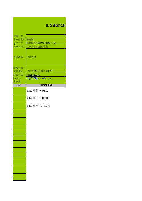
睿博DNA合成订购表
0 0 0 0 0 0 0 0 0 0 0 0 0 0 0 0 0 0 0 0 0 0 0 0 0 0 0 0
ID*
Primer名称
URA-重组-F-0520
URA-重组-R-0520
URA-重组-F2-0520
引物合成订购表
睿博兴科生物技术有限公司
引物合成订购表
com>
序列(5'to3')
TTCCATTGCATCTCCCTTTTACTCTCGTTCAAGACACTGATTTGATACGCTTTCTGTACGttgcgca gcctgaatggcga
提供量OD 纯化方式
4
HPLC
单价
修饰
80
2
4
HPLC
80
2
0
2
0
2
0202020
2
0
2
0
2
0
2
0
2
0
0 0 0 0 0 0 0 0
4
HPLC
4 4 4 4 4 4 4 4 4 4
0 0 0 0 0 0 0 0 0 0 0 0 0 0 0 0 0 0 0 0 0 0 0 0 0 0 0 0 0 0 0 0 0 0 0 0 0 0 0 0 0 0 0 0 0 0 0
北京睿博兴科生物技术有限公司 www.ruib iotech.c om
合成部:dna@ 测序部:seq@
订单要求: 1.此表格仅 针对Email订单 使用,传真 订单请勿使 用。
总碱基数 240 碱基数 分装管数
80
2
2.因此订单是电脑自动处理,订单发送前请仔细核对信 息, 订单接收2小时后将不能再更改。
0 0 0 0 0 0 0 0 0 0 0 0 0 0 0 0 0 0 0 0 0 0 0 0 0 0 0 0 0 0 0 0 0 0 0 0 0 0 0 0 0 0 0 0 0 0 0
帕克霍夫尼因公司工业胶管产品说明书

2Parker Hannifin CorporationIndustrial Hose Products LENGTHS: 100 ft., lengths up to 200 ft. available on quotation.COUPLINGS: For permanent crimp specifications, refer to CrimpSource. Other available coupling options: Series 7670. For assembly guidelines and additional coupling options, refer to NAHAD Industrial Hose Assembly Guidelines.WARNING! Combination nipple and bands reduce the workingpressure of the assembly to less than the hose’s maximum working pressure. Refer to NAHAD Assembly Guidelines for working pressure.!Compatible with 96% of chemicals and solvents >>Applications• Chemical Transport• Storage Tank T ransfer POLY-CHEM ®Corrugated Hose Series 7274The Poly-Chem hose is designed to handle many types of chemicals and solvents in both full suction and discharge applications. This series has a corrugated cover that provides maximum flexibility for easy handling. The clear cross-linked polyeth-ylene tube will handle many types of chemicals, acids and solvents without leaching and contaminating the product conveyed. Refer to the chemical guide in the Safety and T echnical Data section of this catalog, or contact Parker to determine compatibility with specific chemicals and applications. Validated permanent crimp specs are available.4:1 Design factorWARNING! Elevated temperatures can change chemical resistance rat-ings. Most chemical resistance guides are based on testing performed at ambient 70°F (21°C) and higher temperatures are likely to change these ratings. Many chemicals will become more aggressive as temperatures increase, reducing the ability of materials to withstand them. It is the users responsibility to determine if the hose is compatible with the application. Compatibility information can be requested from Parker for chemicals at elevated temperatures, it will be necessary for users to perform compati-bility testing if no data exists for the chemical at the temperature desired. 。
- 1、下载文档前请自行甄别文档内容的完整性,平台不提供额外的编辑、内容补充、找答案等附加服务。
- 2、"仅部分预览"的文档,不可在线预览部分如存在完整性等问题,可反馈申请退款(可完整预览的文档不适用该条件!)。
- 3、如文档侵犯您的权益,请联系客服反馈,我们会尽快为您处理(人工客服工作时间:9:00-18:30)。
Product Name:
(-)-Huperzine A CAS No.:
102518-79-6Product Data Sheet
Cat. No.:
HY-17387MWt:
242.32Formula:
C15H18N2O Purity :
>98%
Solubility:Mechanisms:
Biological Activity:
Pathways:Neuronal Signaling; Target:AChE DMSO
g y Huperzine A, an active Lycopodium alkaloid extracted from traditional Chinese herb, is a potent,selective and reversible acetylcholinesterase (AChE) inhibitor and has been widely used in China for
the treatment of Alzheimer's disease (AD).
IC50 value:
Target: AChE Huperzine A exhibited protective effects against d-gal-induced hepatotoxicity and inflamm-aging by inhibiting AChE activity and via the activation of the cholinergic anti-inflammatory pathway. The huperzine A mechanism might be involved in the inhibition of DAMPs-mediated NF-κB nuclear References:
[1]. Burshtein G, Friedman M, Greenberg S, Hoffman A. Transepithelial Transport of a Natural Cholinesterase Inhibitor, Huperzine A, along the Gastrointestinal Tract: the Role of Ionization on
Absorption Mechanism. Planta Med. 2013 Jan 23.[2]. Ruan Q, Liu F, Gao Z, et al. The anti-inflamm-aging and hepatoprotective effects of huperzine A p g localization and activation. Huperzine A is a potential therapeutic agent for Alzheimer's disease....[]g g p p p
in d-galactose-treated rats. Mech Ageing Dev. 2013 Jan 8. pii: S0047-6374(12)00182-0.[3]. Zhang HY. New insights into huperzine A for the treatment of Alzheimer's disease. Acta
Pharmacol Sin. 2012 Sep;33(9):1170-5.[4]. Wang J, Zhang HY, Tang XC. Huperzine a improves chronic inflammation and cognitive decline
in rats with cerebral hypoperfusion. J Neurosci Res. 2010 Mar;88(4):807-15. doi: 10.1002/jnr.22237.[5]. Park P, Schachter S, Yaksh T. Intrathecal huperzine A increases thermal escape latency and decreases flinchin...
Caution: Not fully tested. For research purposes only
Medchemexpress LLC。