2SB1694T106中文资料
Belimo 产品B216 型号15 技术数据表说明书

B216•Stainless Steel Ball and StemType overviewType DNB21615Technical dataFunctional data Valve size0.5" [15]Fluid chilled or hot water, up to 60% glycolFluid Temp Range (water)0...250°F [-18...120°C]Body Pressure Rating600 psiClose-off pressure ∆ps200 psiFlow characteristic equal percentageServicing maintenance-freeFlow Pattern2-wayLeakage rate0% for A – ABControllable flow range75°Cv16No Characterized Disc TRUECv Flow Rating A-port: as stated in chart B-port: 70% of A – ABCvMaterials Valve body Nickel-plated brass bodyStem stainless steelStem seal EPDM (lubricated)Seat PTFECharacterized disc No Disc (full flow)Pipe connection NPT female endsO-ring EPDM (lubricated)Ball stainless steelSuitable actuators Non-Spring TRLRB(X)NRSpring TFRB(X)LFSafety notesWARNING: This product can expose you to lead which is known to the State of California tocause cancer and reproductive harm. For more information go to B216ApplicationMode of operationProduct featuresThis valve is typically used in air handling units on heating or cooling coils, and fan coil unit heating or cooling coils. Some other common applications include Unit Ventilators, VAV box re-heat coils and bypass loops. This valve is suitable for use in a hydronic system with variable flow.Flow/Mounting detailsTwo-way valves should be installed with thedisc upstream.Product featuresSY7~8 Replacement HandwheelDimensionsType DN B21615LRB, LRXAB C D E F H1H29.4" [239]2.4" [60]5.6" [141]5.0" [127]1.3" [33]1.3" [33]1.2" [30]1.1" [28]TRAB C D E F 3.7" [95]2.4" [60]5.2" [132]4.6" [117]1.3" [33]1.3" [33]B216TFRB, TFRXA B C D E F6.6" [167] 2.4" [60] 5.5" [139] 4.7" [120] 1.5" [39] 1.5" [39]LFA B C D E F7.9" [200] 2.4" [60] 6.1" [154] 5.5" [140] 1.3" [33] 1.3" [33]ARB N4, ARX N4, NRB N4, NRX N4A B C D E F11.4" [289] 2.4" [60]7.7" [196]7.0" [179] 3.1" [80] 3.1" [80]FootnotesNEMA 4X, Modulating Control, Non-Spring Return, 24 V, for DC 2...10 V or 4...20 mATechnical dataElectrical dataNominal voltageAC/DC 24 V Nominal voltage frequency 50/60 Hz Power consumption in operation 3.5 W Power consumption in rest position 0.6 WTransformer sizing 5 VA (class 2 power source)Electrical Connection Screw terminal (for 26 to 14 GA wire), 1/2" conduit connectorOverload Protectionelectronic throughout 0...95° rotation Functional dataOperating range Y 2...10 VOperating range Y note 4...20 mA w/ ZG-R01 (500 Ω, 1/4 W resistor)Input Impedance 100 kΩ for 2...10 V (0.1 mA), 500 Ω for 4...20 mA Position feedback U 2...10 V Position feedback U note Max. 1 mADirection of motion motor selectable with switch 0/1Manual override external push button Angle of rotation Max. 90°Angle of rotation note adjustable with mechanical stop Running Time (Motor)90 s / 90°Noise level, motor 45 dB(A)Position indicationpointer Safety dataDegree of protection IEC/EN IP66/67Degree of protection NEMA/UL NEMA 4XEnclosure UL Enclosure Type 4XAgency ListingcULus acc. to UL60730-1A/-2-14, CAN/CSA E60730-1:02, CE acc. to 2014/30/EU and 2014/35/EU Quality Standard ISO 9001Ambient temperature -22...122°F [-30...50°C]Ambient temperature note -40...50°C for actuator with integrated heating Storage temperature -40...176°F [-40...80°C]Ambient humidity Max. 100% RH Servicingmaintenance-freeMaterialsHousing material Die cast aluminium and plastic casing†Rated Impulse Voltage 800V, Type of action 1.AA, Control Pollution Degree 3AccessoriesElectrical accessories Description TypeBattery backup system, for non-spring return models NSV24 USBattery, 12 V, 1.2 Ah (two required)NSV-BATAuxiliary switch 1 x SPDT add-on S1AAuxiliary switch 2 x SPDT add-on S2AFeedback potentiometer 140 Ω add-on, grey P140A GRFeedback potentiometer 1 kΩ add-on, grey P1000A GRFeedback potentiometer 10 kΩ add-on, grey P10000A GRFeedback potentiometer 2.8 kΩ add-on, grey P2800A GRFeedback potentiometer 500 Ω add-on, grey P500A GRFeedback potentiometer 5 kΩ add-on, grey P5000A GR Electrical installationINSTALLATION NOTESProvide overload protection and disconnect as required.Actuators may be connected in parallel. Power consumption and input impedance must beobserved.Actuators may also be powered by DC 24 V.Only connect common to negative (-) leg of control circuits.A 500 Ω resistor (ZG-R01) converts the 4...20 mA control signal to 2...10 V.Actuators are provided with a numbered screw terminal strip instead of a cable.Meets cULus requirements without the need of an electrical ground connection.Warning! Live electrical components!During installation, testing, servicing and troubleshooting of this product, it may be necessaryto work with live electrical components. Have a qualified licensed electrician or other individualwho has been properly trained in handling live electrical components perform these tasks.Failure to follow all electrical safety precautions when exposed to live electrical componentscould result in death or serious injury.Wiring diagrams2...10 V / 4...20 mA ControlDimensions。
利勃海尔挖掘机参数
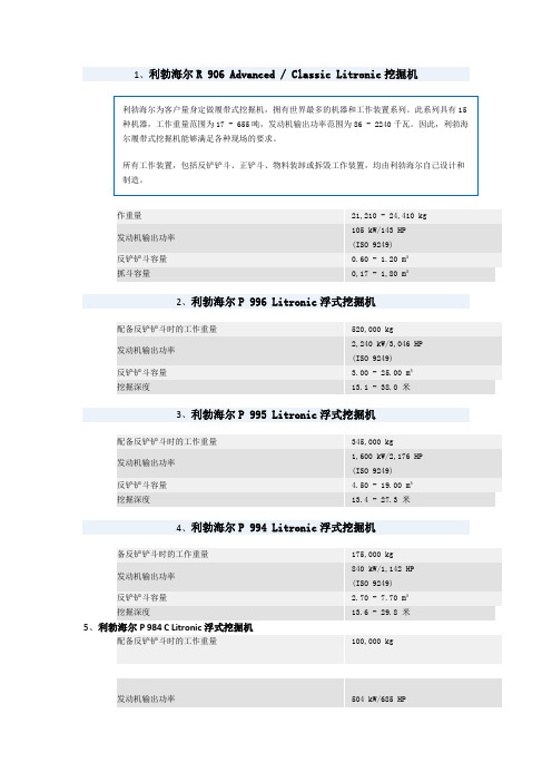
1、利勃海尔R 906 Advanced / Classic Litronic 挖掘机作重量 21,210 - 24,410 kg发动机输出功率 105 kW/143 HP (ISO 9249)反铲铲斗容量 0.60 - 1.20 m³抓斗容量 0,17 - 1,80 m³2、利勃海尔P 996 Litronic 浮式挖掘机配备反铲铲斗时的工作重量 520,000 kg发动机输出功率2,240 kW/3,046 HP(ISO 9249) 反铲铲斗容量 3.00 - 25.00 m³挖掘深度 13.1 - 38.0 米3、利勃海尔P 995 Litronic 浮式挖掘机配备反铲铲斗时的工作重量 345,000 kg发动机输出功率1,600 kW/2,176 HP(ISO 9249) 反铲铲斗容量 4.50 - 19.00 m³挖掘深度 13.4 - 27.3 米4、利勃海尔P 994 Litronic 浮式挖掘机备反铲铲斗时的工作重量 175,000 kg发动机输出功率840 kW/1,142 HP(ISO 9249) 反铲铲斗容量 2.70 - 7.70 m³挖掘深度 13.6 - 29.8 米5、利勃海尔P 984 C Litronic 浮式挖掘机 配备反铲铲斗时的工作重量 100,000 kg 发动机输出功率 504 kW/685 HP(ISO 9249)反铲铲斗容量 2.70 - 7.70 m³挖掘深度8.2 - 16.6 米6、利勃海尔P 974 B Litronic浮式挖掘机配备反铲铲斗时的工作重量68,000 kg发动机输出功率360 kW/490 HP (ISO 9249)反铲铲斗容量 2.60 - 5.60 m³挖掘深度7.5 - 14.3 米7、配备反铲铲斗时的工作重量52,000 kg发动机输出功率270 kW/367 HP (ISO 9249)反铲铲斗容量 2.10 - 4.0 m³挖掘深度8.4 - 13.8 米8、利勃海尔P 954 B Litronic浮式挖掘机配备反铲铲斗时的工作重量42,000 kg发动机输出功率 222 kW/302 HP(ISO 9249)反铲铲斗容量 1.60 - 3.10 m³挖掘深度 7.9 - 11.9 米9、利勃海尔R 9350履带式挖掘机工作重量 302,000 - 310,000 kg发动机输出功率 1,120 kW/1,500 HP (ISO 9249)反铲铲斗容量 18.00 m³ @ 1.8 t/m³正铲斗容量 18.00 m³ @ 1.8 t/m³10、利勃海尔R 9250履带式挖掘机工作重量 249,000 - 253,500 kg发动机输出功率 960 kW/1,287 HP(ISO 9249)反铲铲斗容量 15.00 m³ @ 1.8 t/m³正铲斗容量 15.00 m³ @ 1.8 t/m³ 11利勃海尔R 313 Litronic 挖掘机工作重量 14,200 - 16,700 kg发动机输出功率 74.9 kW/102 HP (ISO 9249)反铲铲斗容量 0.33 - 0.75 m³抓斗容量 0.17 - 0.80 m³12、利勃海尔A 900 C ZW Litronic 轮式挖掘机工作重量 19,650 - 22,000 kg发动机输出功率 105 kW/143 HP(ISO 9249)反铲铲斗容量 0.32 - 0.85 m³抓斗容量 0.10 - 0.48 m³13、利勃海尔R 996 Litronic 大型液压挖掘机工作重量 659.000 - 668.000 kg发动机输出功率 2240 kW/3046 HP (ISO 9249)反铲铲斗容量 33,00 m³ @ 1,8 t/m³正铲斗容量 34,00 m³ @ 1,8 t/m³14、利勃海尔R 995 Litronic 大型液压挖掘机工作重量 439.500 - 448,500 kg发动机输出功率 1600 kW/2176 HP(ISO 9249)反铲铲斗容量 26,50 m³ @ 1,8 t/m³正铲斗容量 26,50 m³ @ 1,8 t/m³15、利勃海尔R 994 B Litronic 大型液压挖掘机工作重量 296.000 - 300.500 kg发动机输出功率 1120 kW/1523 HP (ISO 9249)反铲铲斗容量 18,00 m³ @ 1,8 t/m³正铲斗容量 18,00 m³ @ 1,8 t/m³16、利勃海尔R 994 Litronic 大型液压挖掘机工作重量 229.000 - 226.400 kg发动机输出功率 973 kW/1323 HP(ISO 9249)反铲铲斗容量 13,00 m³ @ 1,8 t/m³正铲斗容量 13,50 m³ @ 1,8 t/m³17、利勃海尔R 984 C Litronic 履带式挖掘机工作重量 118.600 - 125.000 kg发动机输出功率 504 kW/685 HP (ISO 9249)反铲铲斗容量 7,0 m³ @ 1,8 t/m³正铲斗容量 7,0 m³ @ 1,8 t/m³18、利勃海尔R 974 B Litronic 履带式挖掘机工作重量 81 500 - 88 200 kg发动机输出功率 395 kW/537 HP(ISO 9249)反铲铲斗容量 2,20 - 7,00 m³正铲斗容量 4,40 - 7,50 m³抓斗容量1,20 - 2,80 m³19、利勃海尔R 964 B Litronic履带式挖掘机R 964 B Litronic 履带式挖掘机宽敞、舒适的操作员室,以及人机工程学优化工作区域,实现了无疲劳高效操作。
浮油回收船全船技术规格书

目录1总体部分 (4)1.1总则 (4)1.2定义 (4)1.3概述 (5)1.4主要参数 (7)1.5总布置概述 (8)1.6主机 (8)1.7主要性能 (9)2船体结构部分 (18)2.1概述 (18)2.2主要构件尺寸 (18)2.3材料、工艺和检验 (18)2.4结构设计说明 (19)3船体舾装部分 (21)3.1概述 (21)3.2锚泊设备 (21)3.3系泊设备 (22)3.4起重设备 (23)3.5桅墙信号 (23)3.6金属门、窗、盖 (23)3.7梯、栏杆、扶手 (24)3.8救生设备 (25)3.9消防杂件 (25)3.10帆布罩 (26)3.11其它 (26)4舱室舾装部分 (27)4.1概述 (27)4.2舱室及舱室设备 (27)4.3小五金、纺织品及用品 (29)4.4舱室绝缘 (30)4.5甲板敷料 (31)4.6防火门与非金属门 (32)4.7贮藏室 (32)4.8航行设备 (32)4.9船舶标志 (33)4.10舱室舾装备品、供应品 (34)4.11油漆 (34)4.12防腐蚀锌板 (35)5轮机 (36)5.1概述 (36)5.2舱的分隔 (36)5.3主要设备 (37)5.4辅助设备 (41)5.5管系要求 (47)5.6动力系统 (49)5.7船舶系统 (51)5.8绝热和油漆 (56)5.9减振与降噪 (56)5.10机修设备及其它 (57)5.11监测报警 (57)6电气部分 (59)6.1总则 (59)6.2电源装置 (60)6.3配电装置 (61)6.4电缆 (63)6.5电力拖动与控制 (64)6.6照明 (64)6.7船内通信设备 (66)6.8船舶和乘员安全设备 (68)6.9航行设备 (70)6.10无线电设备 (73)6.11控制台 (74)6.12自动化系统 (75)6.13娱乐设备 (76)1总体部分1.1总则本说明书和轮机说明书、电气说明书及其附图的目的是叙述一艘双机双桨推进,可航行于近海航区的浮油回收船的设计、图纸审查、材料、结构、设备、工具、备件、建造、检验、试验、监督、下水、试航、交船等方面的技术说明和要求。
奥德维特说明书

PDA 系列产品的设计、制造、检查、试验及特性都应遵照适合的最新版IEC 和中国GB 标准及国际单位SI 制。
GB/T13730《地区电网数据采集与监控系统通用技术条件》GB/50171-92《电气装置安装工作盘、柜及二次回路接线施工及验收规范》DL/T630《交流采样远动终端通用技术条件》DL/478-92《静态继电保护及安全自动装置通用技术条件》GB/50062-92《电力装置的继电保护和自动装置设计规范》GB/T50063-2008《电力装置的电测量仪表装置设计规范》DL/T587-1996《微机继电保护装置运行管理规程》GB/T13729-2002《远动终端通用技术条件》GB/14285-93《继电保护和安全自动装置技术规程》GB/T17626.12-1998《振荡波抗扰度试验》GB/T17626.11-2008《电压暂降、短时中断和电压变化抗扰度试验》GB/T17626.10-1998《阻尼振荡磁场抗扰度试验》GB/T17626.8-2006《工频磁场的抗扰度试验》GB/T17626.6-2008《射频场感应的传导骚扰抗扰度》GB/T17626.5-2008《浪涌(冲击)抗扰度试验》GB/T17626.4-2008《电快速瞬变脉冲群抗扰度试验》GB/T17626.2-2006《静电放电抗扰度试验》GB/T 14047-1993《量度继电器和保护装置》GB 3836.3-2000《爆炸性气体环境用电气设备 第 3 部 分:增安型"e"》JB/T 10613-2006《数字式电动机综合保护装置》GB/T13850-1998《交流电量转换为模拟量或数字信号的电测量变送器》JJG596-1999《电子式电能表检定规程》GB/T17215.321-2008《静止式有功电能表(1级和2级)》GB/T 22264-2008《安装式数字显示电测量仪表》产品标准Contents 目 录A -01综合电力监控仪PDA-120系列B -13 三相智能型电力仪表 PDA-103系列C -31单相智能型电力仪表 PDA-101系列D -51 智能型电动机保护控制器 PDA-110MRK F -66参考设计图附录产品业绩G -73GB/T17215.322-2008《》静止式有功电能表(0.2S 级和0.5S 级)E -58 低压电动机保护装置 ADVP-1451产品简介功能详表产品特点PDA -120系列综合电力监控仪是北京奥德威特电力科技股份有限公司按IEC 国际标准开发,与当今国际先进技术同步的网络化综合电力监控仪表。
道依茨产品介绍1016

1013/2012/2013
kW
1013/2012/2013
Nm kW Nm kW Nm
1013/2012/2013 1013/2012/2013
187
旋转方向是以泵和压缩机自由端定义的。
左转 右转
PTO „A“
18
技术指标
技术指标
BF6M1 01 3- 24 BF6M1 01 3- 26 BF6M1 01 3- 28 缸数 缸径X冲程(mm) 排量(L )/单缸排量 型式 吸气方式 最大扭矩/转速(N m/r/min ) 燃油消耗率(g/kW.h ) 每缸气门数 压缩比 供油方式 喷油泵 排放 喷射压力(b ar) 重量(kg)(干重) 6 108X130 7.2/1.2 直列水冷 增压中冷 930/1400 200 2 18.1 机械式/电控 单体泵 EUROⅡ/Ⅲ 1200-1600 650 6 108X130 7.2/1.2 直列水冷 增压中冷 192/260/2300 1000/1400 200 2 18.1 机械式/电控 单体泵 EUROⅡ/Ⅲ 1200-1600 650 6 108X130 7.2/1.2 直列水冷 增压中冷 206/280/2300 1050/1400 200 2 18.1 电控 单体泵 EUROⅡ/Ⅲ 1600 650 BF6M201 2- 20 6 101X126 6.06/1.01 直列水冷 增压中冷 147/200/2300 735/1500 200 2 18 机械式/电控 单体泵 EUROⅡ/Ⅲ 1600 550 电控 单体泵 EUROⅡ/Ⅲ 1600 550 BF6M201 2- 22 6 101X126 6.06/1.02 直列水冷 增压中冷 162/220/2500 770/1500 200 4
液压破碎锤型号及选型

液压破碎锤型号及选型液压破碎锤型号及选型(一)2011-09-15 11:07液压破碎锤已经成为液压挖掘机的一个重要作业工具,也有人将液压破碎锤安装在挖掘装载机(又称两头忙)或轮式装载机上进行破碎作业。
1、液压破碎锤的定义液压破碎锤已经成为液压挖掘机的一个重要作业工具,也有人将液压破碎锤安装在挖掘装载机(又称两头忙)或轮式装载机上进行破碎作业。
液压破碎锤,又叫做液压破碎器或液压碎石器(hydraulic breaker),日本、韩国多用此术语。
也有称之为液压锤(hydraulic hammer),芬兰、德国的公司多用此术语。
我国的厂商与用户,有称之为液压破碎机的,也有称之为液压镐、液压炮、破碎头等等,我国国家标准的术语称之为液压冲击破碎器(hydraulic impact breaker)。
名称虽然五花八门,但都是指的同一机具,这种机具是以液体静压力为动力,驱动活塞往复运动,活塞冲程时高速撞击钎杆,由钎杆破碎矿石、混凝土等固体。
本文将这种机具简称为液压锤。
现在液压锤市场十分兴旺,韩国、日本、德国、美国、芬兰、意大利等国的多种型号液压锤充斥我国市场。
国内也有一些厂家提供一些型号的液压锤产品。
液压锤的型号是销售商和用户都十分注意的重要信息,但型号究竟能告诉我们什么信息呢?2、液压锤型号以及其中数字的含义液压锤的型号一般由字母和数字组合而成。
型号的含义是什么,特别是型号中的数字究竟表示什么意思,下面我来解释一些公司液压锤型号以及其中数字的含义。
2.1 型号中数字表示适用挖掘机的机重有一些公司的一些液压锤型号中的数字表示适用挖掘机的机重等级,如GB170型号中GB是韩国工兵公司的缩写(General Breaker),数字170表示此型号液压锤适用于机重为170kN(即17 t)左右的挖掘机,即适用于13~20 t的挖掘机。
以此类推,GB220、GB290表示的是工兵公司液压锤,适用挖掘机的机重分别是22 t、29 t级。
RTU002P02T106中文资料

Absolute maximum ratings (Ta=25°C)
Parameter Drain-source voltage Gate-source voltage Drain current
Total power dissipation Channel temperature Range of storage temperature
Appendix1-Rev1.1
∗1 Pw≤10µs, Duty cycle≤1% ∗2 Each terminal mounted on a recommended land
Continuous Pulsed
Symbol VDSS VGSS ID IDP ∗1 PD ∗2 Tch Tstg
Limits −20 ±12 ±0.25 ±0.5 0.2 150 −55 to +150
No technical content pages of this document may be reproduced in any form or transmitted by any means without prior permission of ROHM CO.,LTD. The contents described herein are subject to change without notice. The specifications for the product described in this document are for reference only. Upon actual use, therefore, please request that specifications to be separately delivered. Application circuit diagrams and circuit constants contained herein are shown as examples of standard use and operation. Please pay careful attention to the peripheral conditions when designing circuits and deciding upon circuit constants in the set. Any data, including, but not limited to application circuit diagrams information, described herein are intended only as illustrations of such devices and not as the specifications for such devices. ROHM CO.,LTD. disclaims any warranty that any use of such devices shall be free from infringement of any third party's intellectual property rights or other proprietary rights, and further, assumes no liability of whatsoever nature in the event of any such infringement, or arising from or connected with or related to the use of such devices. Upon the sale of any such devices, other than for buyer's right to use such devices itself, resell or otherwise dispose of the same, no express or implied right or license to practice or commercially exploit any intellectual property rights or other proprietary rights owned or controlled by ROHM CO., LTD. is granted to any such buyer. Products listed in this document are no antiradiation design.
轴承.V带(jd)

• 直径系列 (右起第三位) 相同内 径,不同直 径系列轴承 的尺寸。
(3)轴承的内径(基本代号右起一二位数字) a) d=10, 12, 15, 17mm时 代号00 01 02 03 例:6201---6表示深沟球轴承、尺寸系列代号(0)2、 d=12mm b) 内径d=20~480mm(代号04~96) d=代号×5(mm) 例:N2208---N表示圆柱滚子轴承、22尺寸系列代号、 d=8×5=40mm
这在购买进口轴承时应该特别注意。由于国内目前的防锈技 术还不是特别到家,所以对轴承体进行防锈处理时很容易留下厚 厚的油迹,拿在手上粘粘稠稠,而国外原装进口的轴承上几乎看 不到防锈油的痕迹,倒是特别细心的行家说进口轴承闻起来有一 种味道,肯定是下了防锈油,只是看不到而已。
• 倒角是否均匀:
仿冒的轴承由于生产技术的限制,倒角部位处理得不尽人意。
当需要表示滚动轴承的防尘盖和密封圈时, 可按下图方法绘制。
一面带防尘盖的通用画法
两面带密封圈的通用画法
内、外圈有无挡边的通用画法
当需要表示滚动轴承有无内圈或外圈、有无挡边 时可按下图的方法在十字符号上附加一短画表示内圈 或外圈无挡边的方向
外圈无挡边
内圈有单挡边
绘出滚动轴承某一零件的通用画法
在装配图中 为了表达滚动轴 承的安装方法, 可画出滚动轴承 的某些零件
(一)、通用画法
1-圆柱滚子轴承
2-斜挡圈
图滚动轴承带附件的剖面线画法
绘制在轴两侧的通用画法
画出外形轮廓的通用画法
• 如需确切地表示滚 动轴承的外形则应 画出其剖面轮廓并 在轮廓中央画出正 立的十字形符号。 • 十字符号不应与剖 面轮廓线接触
滚动轴承附件按外形轮廓绘制的通用画法
- 1、下载文档前请自行甄别文档内容的完整性,平台不提供额外的编辑、内容补充、找答案等附加服务。
- 2、"仅部分预览"的文档,不可在线预览部分如存在完整性等问题,可反馈申请退款(可完整预览的文档不适用该条件!)。
- 3、如文档侵犯您的权益,请联系客服反馈,我们会尽快为您处理(人工客服工作时间:9:00-18:30)。
Transistors
Rev.A 1/2
General purpose amplification (−30V, −1A)
2SB1694
z Application
Low frequency amplifier Driver
z Features
1) A collector current is large.
2) Collector saturation voltage is low. V CE(sat) ≤ −380mV
At I C = −500mA / I B = −25mA z External dimensions (Unit : mm)
z Absolute maximum ratings (T a=25°C)
Parameter Symbol
V CBO
V CEO V EBO I C
I CP P C Tj Tstg Limits −30−30−6−1200150−55 to +150−2
∗Unit V V V A A mW °C °C
Collector-base voltage
Collector-emitter voltage
Emitter-base voltage
Collector current
Power dissipation
Junction temperature Range of storage temperature ∗Single pulse, P W =1ms
z Packaging specifications
z Electrical characteristics (T a=25°C)
Parameter
Symbol Min.Typ.Max.Unit Conditions
V CB = −10V, I E =0A, f =1MHz
f T −320−MHz V CE = −2V, I E =100mA, f =100MHz BV CBO −30−−V I C = −10µA BV CEO −30−−V I C = −1mA BV EBO −6−−V I E = −10µA I CBO −−−100nA V CB = −30V I EBO −−−100nA V EB = −6V
V CE(sat)−−180−380mV I C = −500mA, I B = −25mA h FE 270−680−V CE = −2V, I C = −100mA Cob −7−pF ∗1∗1
Collector-base breakdown voltage Collector-emitter breakdown voltage Emitter-base breakdown voltage Collector cutoff current Emitter cutoff current
Collector-emitter saturation voltage DC current gain
Transition frequency
Corrector output capacitance
∗1 Pulsed
Transistors
Rev.A 2/2
z Electrical characteristic curves
COLLECTOR CURRENT : I C (A)10D C C U R R E N T G A I N : h F E
1000
100Fig.1 DC current gain
vs. collector current
COLLECTOR CURRENT : I C (A)B A S E S A T U R A T I O N V O L T A G E : V B E (s a t ) (V )C O L L E C T O R S A T U R A T I O N V O L T A G E : V C E (s
a t ) (V )
Fig.2 Collector-emitter saturation voltage
base-emitter saturation voltage vs. collector current
COLLECTOR CURRENT : I C
(A)
C O L L E C T O R S A T U R A T I O N V O L T A G E : V C E (s a t ) (V )
Fig.3 Collector-emitter saturation voltage
vs. collector current
BASE TO EMITTER CURRENT : V BE (V)
C O L L
E C T O R C U R R E N T : I C (A )
Fig.4 Grounded emitter propagation
characteristics
EMITTER CURRENT : I E (A)
T R A N S I T I O N F R E Q U E N C Y : f T (M H z )
Fig.5 Gain bandwidth product
vs. emitter current
COLLECTOR CURRENT : I C (A)
Fig.6 Switching time
S W I T C H I N G T I M E : (n s )
C O L L E C T O R O U T P U T C A
P A C I T A N C E : C o b (p F )
E M I T T E R I N P U T C A P A C I T A N C E : C i b (p
F )Fig.7 Collector output capacitance
vs. collector-base voltage Emitter input capacitance vs. emitter-base voltage
EMITTER TO BASE VOLTAGE : V EB (V)
COLLECTOR TO BASE VOLTAGE : V CB (V)
COLLECTOR TO EMITTER VOLTAGE : V CE (V)
C O L L E C T O R C U R R E N T : I C (A )
Fig.8 Safe Operating Area
Appendix
About Export Control Order in Japan
Products described herein are the objects of controlled goods in Annex 1 (Item 16) of Export T rade Control
Order in Japan.
In case of export from Japan, please confirm if it applies to "objective" criteria or an "informed" (by MITI clause)
on the basis of "catch all controls for Non-Proliferation of Weapons of Mass Destruction.
Appendix1-Rev1.1。