EP2C8Q208-A-C8V6-SCH
HQ电动执行器说明书

The HQ electric actuators are designed for quarter turn applications on large sized ball, butterfly, plug valves and dampers.Compact in design but still offering high output torques. Various control options and a wide range of voltages are available to meet youspecifications.High quality electrical components and alloygearing ensure reliability and extended life span. TemperatureAmbient temperature-20 to 70o C (on/off)-20 to 55o C (modulating)Approvals, Features & Benefits• Base to ISO 5211 & DIN 3337 standards • Weatherproof to IP67 (IP68 option) • Die cast aluminium housing • Wide range of torques & options to meet the demands of any site specificationSTANDARD SPECIFICATIONS Enclosure Weatherproof Enclosure IP67 NEMA 4 & 6 (IP68 Option)Space Heater10W (110/220V AC) Anti -condensationPower Supply(dependent on size) 110/220V AC 1PH 50/60Hz ± 10% 380/440/460V AC 3PH 50/60Hz ± 10% 24V DC ± 10%Manual Override Hand wheel c/w Declutching Mechanism Duty Cycle (on -off)S4, 70% Standard, 100% for Max 30minMovement Angle 90o ± 10o (0-110o ) Duty Cycle (modulating) S4, 70% Max 300-1600 start/hour Casing Material Aluminium Alloy, Dry Power Polyester Coated MotorInduction Motor (Reversible)Terminal BlockSpring Loaded Lever Push Type Limit Switches 4 x Open/Close, SPDT, 250 V AC 16A Rating Case Colour BlueTorque Switches 2 x Open/Close, SPDT, 250 V AC 16A Rating ♦♦♦♦ Except HQ -008Electric 1/4 Turn High Torque Actuator80Nm - 3000NmADDITIONAL DATAMax. Square Operating TimeNo. of ISO 5211 Torque OutputDrive* 50 / 60Hz Handle DIN 3337 (Nm) (mm) 90o (sec.) Turns Mounting HQ -008 80 14 16 / 13 10 F07 HQ -015 150 17 25 / 21 10 F07, F10 HQ -020 200 17 25 / 21 11 F07, F10 HQ -030 300 22 31 / 26 13.5 F10, F12 HQ -050 500 22 31 / 26 13.5 F10, F12 HQ -060 600 27 31 / 26 13.5 F10, F12 HQ -080 800 27 37 / 31 16.5 F12, F14 HQ -120 1200 36 37 / 31 16.5 F12, F14 HQ -200 2000 36 112 / 93 49.5 F14***, F16 HQ -300300046112 / 9349.5F14***, F16* Can be machined to suit most valves stems (on request) ** HQ -HRP *** On requestA B C D E F G H* ISO 5211 F07 ISO 5211 F10 ISO 5211 F12 CableEntryWeight Kg ISO 5211 F14 I ISO5211F16 K J HQ -008 258 50 157 100 70 235 120 14 ✓ ✗ ✗ M257.4 (15**)✗ 35 ✗ - 154 HQ -015 338 73 200 142 87 268 160 17 ✓ ✓ ✗ M25 16.6 (23**) ✗ 45 ✗ - 154 HQ -020 338 73 200 142 87 268 160 17 ✓ ✓ ✗ M25 16.6 (23**) ✗ 45 ✗ - 154 HQ -030 368 82 221 160 99 290 180 22 ✗ ✓ ✓ M25 22 (28**) ✗ 52 ✗ - 154 HQ -050 368 82 221 160 99 290 180 22 ✗ ✓ ✓ M25 23 ✗ 52 ✗ - - HQ -060 368 82 221 160 99 290 180 27 ✗ ✓ ✓ M25 23 ✗ 52 ✗ - - HQ -080 410 103 242 186 111 330 210 27 ✗ ✗ ✓ M25 29 ✓ 60 ✗ - - HQ -120 410 103 242 186 111 330 210 36 ✗ ✗ ✓ M25 29 ✓ 60 ✗ - - HQ -200 410 103 242 186 133 563 210 36 95 ✗ ✗ ✗ ✓*** M25 78 ✓ 133 - HQ -3004101032421861335632104695✗✗✗✓***M2578✓133-HQ008 to HQ120 * Can be machined to suit most valves stems (on request) ** HQ -HRP *** On requestHQ -RBP008 to HQ -RBP030HQ200 to HQ300 OPTIONS PIU PotentiometerPCU Proportional Control Unit Input / Output Signal Range: 4-20mA or 0-10V DC CPT Current Position Transmitter (Output 4-20mA) LCU Local Control Unit (Remote/Open/Stop/Close Switch) EXA Explosion Proof Enclosure. ATEX II 2G Eexd IIB T4 FPAFire Proof Actuator 250o C / 150 minsElectric 1/4 Turn High Torque Actuator80Nm - 3000Nm。
EP1C12Q240C8N中文资料(Altera)中文数据手册「EasyDatasheet - 矽搜」

注意 表 1-1: (1) 该参数包括全局时钟引脚.
EP1C3 59,904
1 104
EP1C4 78,336
2 301
EP1C6 92,160
2 185
EP1C12 239,616
2 249
Cyclone器件在四方扁平封装(QFP),并提供节省空间
FineLine ® BGA封装(见
表1-2
通过 1–3).
于接口和支持ASSP和ASIC器件. Altera还提供新低成本串行配置设备
配置Cyclone器件.
特征
Cyclone器件系列具有以下特性:
■ 2,910 20060个LE,见
表1-1
■ 高达294,912 RAM位(36,864字节)
■ 通过低成本串行配置设备支持配置
■ 支持LVTTL,LVCMOS,SSTL-2和SSTL-3 I / O标准
65
EP1C4
—
EP1C6
—
EP1C12
—
EP1C20
—
104
—
—
—
—
—
—
—
249
301
98
185
185
—
—
—
173
185
249
—
—
—
—
233
301
须知 表 1-2: (1) TQFP:薄型四方扁平封装.
PQFP:塑料四方扁平封装. (2) Cyclone器件支持在同一封装内垂直迁移(即,设计人员可以之间迁移
BGA
1.0
441
21×21
文件 修订记录
表1-4
显示修订历史此文档.
表 1-4.文档修订历史记录
V8A02解决方案用户手册V2.1

V8A02解决方案用户手册V2.1目录1. 文档说明 (6)1.1版本说明 (6)1.2专有名词 (6)2. 方案简介 (8)2.1方案概述 (8)2.2 功能特点 (8)2.2.1 支持DVI数据源输入 (8)2.2.2 支持宽屏等多种DVI输入分辨率 (8)2.2.3 发送卡超大带载 (8)2.2.4 功能强大的配套软件 (8)2.2.5 智能在线检测 (8)2.2.6 高刷新频率 (8)2.2.7 高灰度等级 (9)2.2.8 支持各种像素类型 (9)2.2.9 灵活支持各种模组 (9)2.2.10 多样的端口设置功能 (9)2.2.11箱体色度调整 (9)2.2.12 逐点校正功能 (9)2.2.13 集成测试功能 (9)2.2.14 联机配置数据 (9)2.2.15 智能维修 (10)2.2.16 环路备份功能 (10)2.2.17 在线升级固件安全可靠 (10)2.2.18 支持低电压输入 (10)2.2.19 配备指示灯及控制面板接口 (10)2.2.20 支持远距离传输 (10)2.2.21 支持音频传输及电源控制 (10)2.2.22 提供完整的二次开发接口 (10)2.2.24 支持内建PWM恒流 (10)2.2.25 支持低亮度高保真 (10)2.3产品清单 (11)3. 应用概述 (12)3.1 典型应用 (12)3.2 环路备份 (13)3.3 多发送卡 (14)4. 功能详解 (15)4.1 模组支持能力 (15)4.1.1 模组行、列数1~128以内任意 (16)4.1.2 模组数据类型 (16)4.1.3 模组内每扫描串移长度 (17)4.1.4 虚拟模组LED灯点位置多种排列方式 (17)4.2 箱体连接设置 (17)4.2.1 箱体内模组级联方式 (17)4.2.2 端口扩展 (18)4.2.3 端口对开 (19)4.2.4 端口逆序 (20)4.2.5 端口偏移 (20)4.2.6 箱体带载高度、宽度 (20)4.2.7 箱体显示起始的行、列位置 (21)4.2.8 箱体无信号输入时显示内容设置 (21)4.2.9 箱体级联数量 (21)4.2.10 箱体色度调整 (21)4.2.11 箱体逐点色度校正 (22)4.2.12 箱体测试功能 (22)4.3 屏体参数调节 (23)4.3.1 多个LED屏设置 (23)4.3.3 虚拟LED屏的实效果 (24)4.3.4 LED屏亮度调节 (25)4.3.5 LED屏对比度调节 (26)4.3.6 LED屏色温调节 (26)4.3.7 关闭LED屏显示 (27)4.3.8 锁定LED屏内容 (27)4.3.9 LED屏环境监控 (27)4.4 显示性能参数说明 (30)4.4.1 灰度等级 (30)4.4.2 刷新频率 (31)4.4.3 亮度效率 (31)4.4.4 最小OE (31)4.5 发送卡带载 (31)4.6 在线检测 (34)4.7 系统升级 (34)4.8 智能维修 (36)4.8.1 接收卡更换 (36)4.8.2模组替换 (37)5. 使用说明 (39)5.1 连接硬件 (39)5.1.1 发送卡安装方法 (39)5.1.2 接收卡安装方法 (39)5.1.3 多功能卡安装方法 (39)5.2 安装软件 (40)5.2.1 配置要求 (40)5.2.2 安装步骤 (40)5.3 系统设置 (40)5.3.1 显卡设置 (40)5.3.2系统设置 (43)6. 附录 (55)6.1 设备推荐型号 (55)6.1.1 DVI复制器 (55)6.2 选用线缆清单 (55)6.2.1 HDMI转DVI线缆 (55)6.2.2 音频线 (56)6.2.3 双绞线 (56)6.2.4 光纤 (56)1. 文档说明1.1版本说明版本日期说明V2.0 2013-01-09 升级自1.71版本V2.1 2013-07-15 新增接收卡产品1.2专有名词以下是本文中使用的专用术语及解释,便于读者更好的理解文章内容。●软件一系列按照特定顺序组织的计算机数据和指令的集合,本文中特指在计算机上运行的应用软件。
EP2C8Q208C8中文资料(Altera)中文数据手册「EasyDatasheet - 矽搜」
Cyclone II器件手册,第1卷ii内容章修订日期............................................... ............................喜关于本手册............................................... .............................十三如何触点Altera ..........................................................................................................................十三印刷约定....................................................................................................................十三第一节Cyclone II器件系列数据表修订记录.................................................................................................................................... 1-1第1章简介简介............................................................................................................................................低成本嵌入式处理解决方案............................................ ......................................低成本DSP解决方案.................................................................................................................特征...................................................................................................................................................参考文献.........................................................................................................................文档修订历史记录.................................................................................................................1–1 1–1 1–1 1–2 1–9 1–9第2章Cyclone II架构功能说明.......................................................................................................................... 2-1逻辑元件....................................................................................................................................... 2-2LE操作模式........................................................................................................................ 2-4逻辑阵列模块................................................................................................................................ 2-7LAB互连............................................................................................................................ 2-8LAB控制信号......................................................................................................................... 2-8MultiTrack互联..................................................................................................................... 2-10行互连.......................................................................................................................... 2-10列互连.................................................................................................................... 2-12设备路由............................................................................................................................... 2-15全局时钟网络和锁相环.......................................... ..................................... 2-16专用时钟管脚..................................................................................................................... 2-20双用时钟引脚.............................................................................................................. 2-20全局时钟网络................................................................................................................... 2-21全局时钟网络分布.............................................. .............................................. 2-23锁相环.................................................................................................................................................. 2-25嵌入式存储器............................................................................................................................. 2-27内存模式............................................................................................................................... 2-30时钟模式.................................................................................................................................... 2-31M4K路由接口.................................................................................................................. 2-31iii内容嵌入式乘法器........................................................................................................................乘法器模式............................................................................................................................嵌入式乘法器路由接口.............................................. .......................................I / O结构及特点....................................................................................................................外部存储器接口.......................................................................................................可编程驱动强度.....................................................................................................漏极开路输出........................................................................................................................摆率控制...........................................................................................................................总线防护持..........................................................................................................................................可编程上拉电阻............................................. .................................................. ...高级I / O标准支持............................................ .................................................. ..高速差分接口............................................. .................................................系列片上端接.........................................................................................................I / O组........................................................................................................................................多电压I / O接口.................................................................................................................2–32 2–35 2–36 2–37 2–44 2–49 2–50 2–51 2–51 2–51 2–52 2–53 2–55 2–57 2–60第3章配置与测试IEEE标准. 1149.1(JTAG)边界扫描支持........................................... ..................................构造.........................................................................................................................................操作模式...................................................................................................................................配置计划......................................................................................................................... Cyclone II自动单粒子翻转检测........................................... ...........................定制电路....................................................................................................................软件界面.............................................................................................................................文档修订历史记录.................................................................................................................3–1 3–5 3–5 3–6 3–7 3–7 3–7 3–8第4章热插拔和上电复位简介............................................................................................................................................旋风II热插拔规格............................................ ................................................设备可以在电源时会驱动.......................................... ...........................................I / O引脚防护持三态电期间...................................... ......................................在Cyclone II器件热插拔功能实现......................................... ..............上电复位电路...................................................................................................................."唤醒"时间Cyclone II器件........................................ ...............................................结论..............................................................................................................................................文档修订历史记录.................................................................................................................4–1 4–1 4–2 4–2 4–3 4–5 4–5 4–7 4–7第5章直流特性和时序规范运行条件........................................................................................................................... 5-1单端I / O标准.......................................................................................................... 5-5差分I / O标准.............................................................................................................. 5-7DC特性不同针类型............................................ ......................................... 5-11片上端接规格............................................. .............................................. 5-12能量消耗........................................................................................................................... 5-13时序规格.......................................................................................................................... 5-14预,决赛时序规范............................................. ................................ 5-14演出.................................................................................................................................... 5-15 ivCyclone II器件手册,第1卷内容内部时序...............................................................................................................................Cyclone II时钟时序参数............................................. ..............................................时钟网络偏移加法器.......................................................................................................IOE可编程延迟.............................................................................................................不同I默认容性负载/ O标准......................................... .................I / O延迟.......................................................................................................................................最大输入和输出时钟频率............................................ ........................................高速I / O时序规格........................................... ............................................外部存储器接口规范.............................................. ....................................JTAG时序规范..........................................................................................................PLL时序规范............................................................................................................占空比失真.........................................................................................................................DCD测量技术............................................... .................................................. ..参考文献.......................................................................................................................文档修订历史记录...............................................................................................................5–18 5–23 5–29 5–30 5–31 5–33 5–46 5–55 5–63 5–64 5–66 5–67 5–68 5–74 5–74第6章参考和订购信息软体..................................................................................................................................................器件引脚输出.....................................................................................................................................订购信息...........................................................................................................................文档修订历史记录.................................................................................................................6–1 6–1 6–1 6–2第二节.时钟管理修订记录.................................................................................................................................... 6-1第7章锁相环在Cyclone II器件简介............................................................................................................................................ 7-1Cyclone II PLL硬件概述............................................. .................................................. ... 7-2PLL参考时钟产生.............................................. .................................................. ... 7-6时钟反馈模式....................................................................................................................... 7-10正常模式.................................................................................................................................. 7-10零延迟缓冲器模式................................................................................................................ 7-11无补偿模式............................................................................................................... 7-12源同步模式........................................................................................................... 7-13硬件特性.............................................................................................................................. 7-14时钟倍频和科.............................................. .................................................. .. 7-14可编程占空比........................................................................................................... 7-15移相实施.............................................. .................................................. .... 7-16控制信号................................................................................................................................ 7-17手动时钟切换............................................................................................................. 7-20时钟................................................................................................................................................ 7-21全局时钟网络................................................................................................................... 7-21时钟控制模块....................................................................................................................... 7-24全局时钟网络时钟源产生............................................ .......................... 7-26全局时钟网络掉电............................................. .............................................. 7-28vCyclone II器件手册,第1卷。
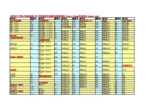
红芯电子FPGA开发板EP2C8Q208_V2脚位对照表 (自动保存的)V1
173 170 168 164 162 134 128 118 116 114 112 107 105 97 101 103
5V D0 D2 D4 D6 A0 GBL_CLK2 A3 A5 A7 A18 RY_BY A22 A21 A9 A11 A13 A15 GND
脚位号 198 197 195 193 192 191 189 188 187 185 182
信号名 LCD12864接口 12864_RST 12864_PSB 12864_DB7 12864_DB6 12864_DB5 12864_DB4 12864_DB3 12864_DB2 12864_DB1 12864_DB0 12864_E/SCLK 12864_RW/SID 12864_RS/CS
红芯电子 FPGA EP2C8Q208 V2 开发板信号及脚位功能对照表()
信号名 SW2(复位按键) SW3(按键) SW4(按键) SW5(按键) SW6(按键) SW7(按键) EXT_CLK (50MHz外部时钟) UART0_RX UART0_TX BUZZER(蜂鸣器) 脚位号 129 27 132 131 130 28 23 信号名 脚位号 4位数码管X2 DIG_EN0(位选线) 3 DIG_EN1(位选线) 4 DIG_EN2(位选线) 5 DIG_EN3(位选线) 6 DIG_EN4(位选线) 8 DIG_EN5(位选线) 12 DIG_EN6(位选线) 11 DIG_EN7(位选线) 10 位选线低有效 DIG_D0(数据总线)208 DIG_D1(数据总线)207 DIG_D2(数据总线)206 DIG_D3(数据总线)205 DIG_D4(数据总线)203 DIG_D5(数据总线)201 DIG_D6(数据总线)200 DIG_D7(数据总线)199 数据总线低有效 信号名 FLASH_CS FLASH_OE FLASH_WE FLASH_RESET FLASH_A0 FLASH_A1 FLASH_A2 FLASH_A3 FLASH_A4 FLASH_A5 FLASH_A6 FLASH_A7 FLASH_A8 FLASH_A9 FLASH_A10 FLASH_A11 FLASH_A12 FLASH_A13 FLASH_A14 FLASH_A15 FLASH_A16 FLASH_A17 FLASH_A18 FLASH_A19 FLASH_A20 FLASH_A21 FLASH_A22 RY_BY FLASH_D0 FLASH_D1 FLASH_D2 FLASH_D3 脚位号 176 175 108 110 162 179 135 134 133 128 127 118 117 105 96 97 99 101 102 103 104 161 116 115 106 107 112 114 173 171 170 169 SRAM_D0 SRAM_D1 SRAM_D2 SRAM_D3 173 171 170 169 信号名 SRAM(512K X 8) SRAM_CS SRAM_OE SRAM_WE SRAM_A0 SRAM_A1 SRAM_A2 SRAM_A3 SRAM_A4 SRAM_A5 SRAM_A6 SRAM_A7 SRAM_A8 SRAM_A9 SRAM_A10 SRAM_A11 SRAM_A12 SRAM_A13 SRAM_A14 SRAM_A15 SRAM_A16 SRAM_A17 SRAM_A18 脚位号 113 175 108 162 179 135 134 133 128 127 118 117 105 96 97 99 101 102 103 104 161 116 信号名 SDRAM SDRAM_A0 SDRAM_A1 SDRAM_A2 SDRAM_A3 SDRAM_A4 SDRAM_A5 SDRAM_A6 SDRAM_A7 SDRAM_A8 SDRAM_A9 SDRAM_A10 SDRAM_A11 SDRAM_D0 SDRAM_D1 SDRAM_D2 SDRAM_D3 SDRAM_D4 SDRAM_D5 SDRAM_D6 SDRAM_D7 SDRAM_D8 SDRAM_D9 SDRAM_D10 SDRAM_D11 SDRAM_D12 SDRAM_D13 SDRAM_D14 SDRAM_D15 SDRAM_BA0 SDRAM_BA1 SDRAM_CS 脚位号 90 95 94 92 77 76 75 74 72 70 89 69 37 39 40 41 43 44 45 46 61 60 59 58 57 56 47 48 87 88 86 信号名 LCD1602接口 1602_RS 1602_RW 1602_E 1602_D0 1602_D1 1602_D2 1602_D3 1602_D4 1602_D5 1602_D6 1602_D7
奥里安特电机产品操作手册说明书

HM-9264-2AC Standard Motors Conduit Box TypeInduction MotorThank you for purchasing an Oriental Motor product.This Operating Manual describes product handling procedures and safety precautions.• Please read it thoroughly to ensure safe operation. • Always keep the manual where it is readily available.Before useOnly qualified personnel should work with the product.Use the product correctly after thoroughly reading the section “Safety precautions”.Should you require the inspection or repair of internal parts, contact the Oriental Motor office where you purchased the product. The product described in this manual has been designed andmanufactured for use as an internal component for general industrial equipment, and must not be used for any other purpose. Oriental Motor Co., Ltd. is not responsible for any damage caused through failure to observe this warning.Standard and CE MarkingMotors are recognized by UL. Recognized name are motor model name. Voluntary display of the CE mark conforming to the Low Voltage Directives. StandardsUL 1004, UL 2111, CSA C22.2 No.100, CSA C22.2 No.77 Standards File No. UL File No.E64197 Applications for standardEN 60034-1, EN 60034-5, EN 60664-1A Running Heating Test and a Locked-Rotor Test has beenconducted with a aluminum radiation plate of size indicated below. For the motor with a gearhead, tests has been conducted with a gearhead instead of the radiation plate.First number in motor nameSize [mm (in.)] Thickness [mm (in.)]Material4 135 × 135 (5.31 × 5.31) 5 (40 W) 165 × 165 (6.50 × 6.50) 5 (60 W, 90 W)200 × 200 (7.87 × 7.87)5 (0.20)AluminiumInstallation conditionsOvervoltage category II, Pollution degree 3 (except for the motor mounting surfase and conduit opening), Class I equipment (For EN/IEC standards)When the machinery to which the motor is mounted requiresovervoltage category III specifications, connect to power supply via an isolation transformer.Hazardous substancesRoHS (Directive 2002/95/EC 27Jan.2003) compliant∗ 5IK60GU-FCH , 5IK60GU-ECH , 5IK60GU-SH , 5IK90GU-FCH , 5IK90GU-ECH and 5IK90GU-SH do not comply with the hazardous substances.The precautions described below are intended to prevent danger or injury to the user and other personnel through safe, correct use of the product. Use the product only after carefully reading and fully understanding these instructions.WarningHandling the product without observing theinstructions that accompany a “Warning” symbol may result in serious injury or death.CautionHandling the product without observing theinstructions that accompany a “Caution” symbol may result in injury or property damage.NoteThe items under this heading contain importanthandling instructions that the user should observe to ensure safe use of the product.Warning• Do not use the product in explosive or corrosive environments, in the presence of flammable gases, locations subjected to splashing water, or near combustibles. Doing so may result in fire, electric shock or injury.• Assign qualified personnel the task of installing, wiring,operating/controlling, inspecting and troubleshooting the product. Failure to do so may result in fire, electric shock or injury. • Do not transport, install the product, perform connections or inspections when the power is on. Always turn the power offbefore carrying out these operations. Failure to do so may result in electric shock.• Turn off the power in the event the overheat protection device (thermal protector) is triggered. Failure to do so may result in injury or damage to equipment, since the motor will start abruptly when the overheat protection device (thermal protector) is automatically reset.• To prevent the risk of electric shock, use the motor for class I equipment only.Motore zur Verwendung in Geräten der Schutzklasse I.• Install the motor in an enclosure in order to prevent electric shock or injury.• Install the motor so as to avoid contact with hands, or ground it to prevent the risk of electric shock.Die Gehäuse der Motore sind mit einer Schraube undZahnscheibe sicher mit dem geerdeten Gehäuse des Gerätes zu verbinden.• Keep the input power voltage within the specification to avoid fire and electric shock.• Connect the cables securely according to the wiring diagram in order to prevent fire and electric shock.• Do not forcibly bend, pull or pinch the lead wires. Doing so may result in fire and electric shock.• Turn off the power in the event of a power failure, or the motor will suddenly start when the power is restored and may cause injury or damage to equipment.• Do not touch the connection terminal of the capacitor immediately after the power is turned off (for a period of 30 seconds). Theresidual voltage may cause electric shock.• Do not disassemble or modify the motor. This may cause electric shock or injury.Caution• Do not use the motor beyond its specifications, or electric shock, injury or damage to equipment may result.• Do not touch the motor during operation or immediately after stopping. The surface is hot and may cause a burn.• Do not hold the motor output shaft or motor lead wires. This may cause injury.• Keep the area around the motor free of combustible materials in order to prevent fire or a burn.• To prevent the risk of damage to equipment, leave nothing around the motor that would obstruct ventilation.• To prevent bodily injury, do not touch the rotating parts (output shaft, cooling fan) of the motor during operation.• When an abnormality is noted, turn off the power immediately, or fire, electric shock or injury may occur.• The motor’s surface temperature may exceed70 °C, even under normal operating conditions. Ifa motor is accessible during operation, post thewarning label shown in the figure in aconspicuous position to prevent the risk of skinburn(s).Warning label• To dispose of the motor, disassemble it into parts and components as much as possible and dispose of individual parts/components as industrial waste.Checking the productVerify that the items listed below are included. Report any missing or damaged items to the branch or sales office from which you purchased the product.• Motor...............................................1 unit• OPERATING MANUAL................1 copyChecking the model nameCheck the model number against the number indicated on the product.Model Model Model4IK25GN-FCH 4IK25GN-ECH 4IK25GN-SH4IK25AA-FCH 4IK25AA-ECH 4IK25AA-SH5IK40GN-FCH 5IK40GN-ECH 5IK40GN-SH5IK40AA-FCH 5IK40AA-ECH 5IK40AA-SH5IK60GE-FCH 5IK60GE-ECH 5IK60GE-SH5IK60A-FCH 5IK60A-ECH 5IK60A-SH5IK60GU-FCH 5IK60GU-ECH 5IK60GU-SH5IK90GE-FCH 5IK90GE-ECH 5IK90GE-SH5IK90A-FCH 5IK90A-ECH 5IK90A-SH5IK90GU-FCH 5IK90GU-ECH 5IK90GU-SH Location for installationThe motor is designed and manufactured for installation in equipment.Install it in a well-ventilated location that provides easy access for inspection. The location must also satisfy the following conditions: • Inside an enclosure that is installed indoors (provide vent holes) • Operating ambient temperature−10 to +40 °C (+14 to +104 °F) (non-freezing)−10 to +50 °C (+14 to +122 °F) for three-phase 200 V• Operating ambient humidity 85%, maximum (non-condensing) • Area that is free from an explosive atmosphere or toxic gas (such as sulfuric gas) or liquid• Area not exposed to direct sun• Area free of excessive amount dust, iron particles or the like• Area not subject to splashing water (storms, water droplets), oil (oil droplets) or other liquids• Area free of excessive salt• Area not subject to continuous vibration or excessive shocks• Area free of excessive electromagnetic noise (from welders,power machinery, etc.)• Area free of radioactive materials, magnetic fields or vacuum• 1000 m (3300 ft.) or less above sea levelHow to install the motor• Round shaft typeDrill holes on the mounting plate and fix the motor on the plateusing screws, nuts, and washers (not supplied). Be careful there is nogap between the motor installation surface and the bracket.First number inmotor modelScrew size Tightening torque [N·m (lb-in)]4 M5 2.5(22)5 M6 3.0(26)Do not insert the motor into the mounting hole at anangle or force it in, as this may scratch the flange pilotsection and damage the motor.• Pinion shaft typeDrill holes on the mounting plate and fix the motor and gearhead on the plate using screws supplied with the gearhead. Be careful there is no gap between the motor flange and the gearhead.For details of installation, see the operating manual provided with the gearhead, which is sold separately.Use the gearhead with pinion shaft which is identicalwith one of motor.• Motor with cooling fanWhen installing a motor with cooling fan onto a device, leave10 mm (0.39 in.) or more behind the fan cover or open a ventilation hole so that the cooling inlet on the back of the motor cover is not blocked.Insulate all the wire connections, such as the connection between the motor and the capacitor connection.When the single-phase motor is run in only one direction, unused lead wires should be insulated.Ground the motor using a Protective Earth lead wire (green/yellow). The direction of motor rotation is as viewed from the side of the motor’s output shaft. The motor rotates in a clockwise (CW) and counterclockwise (CCW) direction.• Insulation class of this motor is B. Make sure that themotor case temperature does not exceed 90 °C(194 °F) during operation of the motor. Operationexceeding case temperature 90 °C (194 °F) maysignificantly deteriorate the coils and ball bearings ofthe motor and shorten the motor’s life span. Motorcase temperature can be measured by fixing athermometer on the motor surface. It can also bemeasured using thermo tape or a thermocouple.• To change rotation direction of the single-phasemotor, wait until the motor completely stops.Otherwise its direction may not change or may takemuch time to change.Rotating direction of the gearhead output shaftThe rotating direction of the gearhead output shaft may be opposite that of the motor shaft, depending on the gear ratio. For the rotating direction of the output shaft of a specific gearhead used, refer to the operating manual for the gearhead. Connection method to a terminal box• Open the terminal box and connect wires.• Use applicable cable ground and conduit for conduit opening. • After connecting, close the terminal box with the terminal cover. • Terminal cover screws tightening torqueSingle-phase 25 W, 40 W/Three-phase: 0.3 N·m (2.6 lb-in) Single-phase 60 W, 90 W: 1 N·m (8.8 lb-in)• Single-phase 25 W, 40 W/Three-phase••Connect the motor according to the figure.The connection method will vary, depending on the directionClockwiseLNCounterclockwiseLN∗ NC: Not connect. Three-phase motorsConnect the motor according to the figure.When connected according to the connection diagram, the motor will operate in the clockwise direction (CW) as viewed from the motor’s output shaft. To change the direction of rotation, change any two connections between U, V and W.ClockwiseL2 (S)L1 (R)L3 (T)Motors have a continuous rating.This motor is equipped with the feature listed below to prevent the motor from burning out as a result of abnormal heating which maybe caused by misapplication.• Thermal protection“TP” is stamped on the motor nameplate. The motor has an “auto reset” type thermal protector built into its motor coil. When themotor reaches a predetermined temperature, the internal thermal protector is activated and the motor is stopped.Always turn the power off before performing inspections.Thermal protector activation rangePower is turned off at 130±5 °C (266±9 °F)Power is turned back on at 82±15 °C (180±27 °F)When the motor cannot be operated correctly, refer to the contents provided in this section and take appropriate action. If the problem persists, contact your nearest office.Phenomena CheckitemsMotor does not rotate or rotates slowly. • Check the power supply voltage.• Connect the power supply and the motor correctly.• If terminal blocks or crimp terminals are used, check them for poor connection. • Keep the load at or below the allowable value.Motor sometimes rotates and stops. • Connect the power supply and the motor correctly.• If terminal blocks or crimp terminals are used, check them for poor connection.The motor rotates in the direction opposite to the specified direction. • Connect correctly by referring to “Wiring diagram.”• The rotating direction of the motor output shaft may be different from that of the gearhead output shaft depending on the gear ratio of the gearhead. See the operating manual for the gearhead.• The rotating direction is indicated as viewed from the motor output shaft. Check the reference direction.Motor temperature abnormally high [Motor case temperature exceeds 90 °C (194 °F)] • Check the power supply voltage. • Review the ventilation condition.Noisy operation • Assemble the motor and gearheadcorrectly by referring to the operatingmanual for the gearhead.• Assemble a gearhead of the same piniontype as the motor.• Unauthorized reproduction or copying of all or part of thismanual is prohibited.• Oriental Motor shall not be liable whatsoever for any problems relating to industrial property rights arising from use of anyinformation, circuit, equipment or device provided orreferenced in this manual.• Characteristics, specifications and dimensions are subject tochange without notice.• While we make every effort to offer accurate information in the manual, we welcome your input. Should you find uncleardescriptions, errors or omissions, please contact the nearestoffice.• is a registered trademark or trademark ofOriental Motor Co., Ltd., in Japan and other countries.© Copyright ORIENTAL MOTOR CO., LTD. 2008Printed on Recycled Paper • Please contact your nearest Oriental Motor office for further information.Headquarters Tokyo, JapanTel:(03)3835-0684 Fax:(03)3835-1890Tel:01 47 86 97 50 Fax:01 47 82 45 16Tel:(02)8228-0707 Fax:(02)8228-0708 Technical Support Tel:(800)468-39828:30 A.M. to 5:00 P.M., P.S.T. (M-F)7:30 A.M. to 5:00 P.M., C.S.T. (M-F)E-mail:*****************************Headquarters and Düsseldorf Office Tel:0211-52067-00 Fax:0211-52067-099 Munich Office Tel:089-3181225-00 Fax:089-3181225-25 Hamburg Office Tel:040-76910443 Fax:040-76910445Tel:01256-347090 Fax:01256-347099Tel:02-93906346 Fax:02-93906348Tel:(6745)7344 Fax:(6745)9405KOREATel:(032)822-2042~3 Fax:(032)819-8745Tel:(03)22875778 Fax:(03)22875528Tel:66-2-254-6113 Fax:66-2-254-6114。
EDA选择题含答案

一、选择题:(20分)1.大规模可编程器件主要有FPGA、CPLD两类,下列对CPLD结构与工作原理的描述中,正确的是:___D__A. CPLD是基于查找表结构的可编程逻辑器件B. CPLD即是现场可编程逻辑器件的英文简称C. 早期的CPLD是从FPGA的结构扩展而来D. 在*ilin*公司生产的器件中,*C9500系列属CPLD结构2.基于VHDL设计的仿真包括有①门级时序仿真、②行为仿真、③功能仿真和④前端功能仿真这四种,按照自顶向下的设计流程,其先后顺序应该是:_________DA.①②③④B.②①④③C.④③②①D.②④③①3.IP核在EDA技术和开发中具有十分重要的地位,IP分软IP、固IP、硬IP;下列所描述的IP核中,对于固IP的正确描述为:__________DA.提供用VHDL等硬件描述语言描述的功能块,但不涉及实现该功能块的具体电路B.提供设计的最总产品——模型库C.以可执行文件的形式提交用户,完成了综合的功能块D.都不是4.下面对利用原理图输入设计方法进行数字电路系统设计,哪一种说法是正确的:__________BA.原理图输入设计方法直观便捷,很适合完成较大规模的电路系统设计B.原理图输入设计方法一般是一种自底向上的设计方法C.原理图输入设计方法无法对电路进行功能描述D.原理图输入设计方法不适合进行层次化设计5.在VHDL语言中,下列对进程(PROCESS)语句的语句结构及语法规则的描述中,不正确的是:_______DA.PROCESS为一无限循环语句B.敏感信号发生更新时启动进程,执行完成后,等待下一次进程启动C.当前进程中声明的变量不可用于其他进程D.进程由说明语句部分、并行语句部分和敏感信号参数表三部分组成6.对于信号和变量的说法,哪一个是不正确的:_________AA.信号用于作为进程中局部数据存储单元B.变量的赋值是立即完成的C.信号在整个结构体的任何地方都能适用D.变量和信号的赋值符号不一样7.下列状态机的状态编码,_________方式有“输出速度快、难以有效控制非法状态出现”这个特点。
MCC电路保护器说明书

FeaturesMaximum Ratings8.0 AmpSchottky Rectifier 20 to 100 VoltsElectrical Characteristics @ 25°C Unless Otherwise Specified•Operating Junction Temperature Range: -55⁰C to +150⁰C •Storage Temperature Range: -55⁰C to +150⁰C•High Current Capability •Low Forward Voltage•For Surface Mount Application•Lead Free Finish/RoHS Compliant(Note 1) ("P" Suffix D esignates Compliant. See O rdering I nformation)•Epoxy Meets UL 94 V-0 Flammability Rating •Moisture Sensitivity Level 1•Halogen Free. “Green” Device (Note 2)SK845L SK84545V 31.5V 45V SK835L SK83535V 24.5V 35V SK84L SK8440V 28V 40V SK82L SK8220V 14V 20V SK83L SK8330V 21V 30V MCC Part Number Device Marking MaximumRecurrent Peak Reverse VoltageMaximumRMS VoltageMaximum DCBlockingVoltageTypical Junction CapacitanceC J400pFMeasured at 1.0MHz,V R =4.0VMaximum DC Reverse Current a t Rated DC Blocking Voltage I R0.1m A 10m A T J =25⁰C ;T J =100⁰CPeak Forward Surge CurrentI FSM200A8.3ms,H alf S ineV F0.65V I F M =8.0A;Average Forward CurrentI F(AV)8.0A T L =95⁰C Maximum Instantaneous Forward Voltage0.80V Note:1.High Temperature Solder Exemptions Applied, S ee EU Directive Annex 7a .2.Halogen free "Green” products are defined as those which contain <900ppm bromine,<900ppm chlorine (<1500ppm total Br + Cl) and <1000ppm antimony compounds.3.Mounted on P.C.B. With 0.6" x 0.6" (16 mm x 16 mm) Copper Pad AreasSK82L-86L SK88L-810L T J =25⁰C SK86L SK88L SK810LSK86SK88SK81060V 60V 80V 80V 100V100V42V 56V 70V•Typical Thermal Resistance (Note 3) : 50o C/W Junction to Ambient •Typical Thermal Resistance (Note 3) : 18o C/W Junction to LeadCurve Characteristics25125150012345678910A v e r a g e F o r w a r d C u r r e n t (A)Fig. 1 - Forward Current Derating Curve5075100Lead Temperature (°C)1100255075100125150175200225P e a k F o r w a r d S u r g e C u r r e n t (A)Fig. 2 - Maximum Non-Repetitive Peak Forward Surge10Number of Cycles at 60 Hz0.020.050.20.525200.010.11100.00.10.20.30.40.50.60.70.80.91.0Instantaneous Forward Voltage (V)I n s t a n t a n e o u s F o r w a r d C u r r e n t (A )Fig. 3 - Typical Instantaneous Forward Characteristics0.020.050.20.525200.010.1110Instantaneous Forward Voltage (V)I n s t a n t a n e o u s F o r w a r d C u r r e n t (A )Fig. 4 - Typical Instantaneous Forward Characteristics110100100010000I n s t a n t a n e o u s R e v e r s e L e a k a g e C u r r e n t (μA )Fig. 5 - Typical Reverse Leakage CharacteristicsPercent of Rated Peak Reverse Voltage (%)0.1110100100010000I n s t a n t a n e o u s R e v e r s e L e a k a g e C u r r e n t (μA )Fig. 6 - Typical Reverse Leakage CharacteristicsPercent of Rated Peak Reverse Voltage (%)Ordering InformationDevice PackingPart Number-TP Tape&Reel: 3Kpcs/Reel。