UM71new
Mircom 火警报警器 MS-710U 说明书

Features• Dual Action • Key resettable • Terminal connectors • Gold plated SPST contacts • Optional auxiliary contacts • High-gloss red enamel finish • Plastic breakrod• Meets ADA 5 lb. maximum manual-force •Mounts on standard single gang box, Mircom’s BB-700 surface metal backbox or BB-700WP weather proof backboxMircom reserves the right to make changes at any time without notice in prices, colours, materials, components, equipment, specifications and models and also to discontinue models.METAL FIRE ALARM STATION MS-710UDescriptionMircom’s MS-710U Manual Station provides manual fire reporting. This high quality, die-cast metal manual station is a dual action unit with SPST contacts and terminal strip connections. The normally open contact, which closes when the manual station is activated, is rated for 1 amp, 30 VDC. The contacts are gold plated to avoid the risk of corrosion.The MS-710U is available with a CAT-30 lock and keys and mounts on a standard single gang backbox, Mircom’s BB-700 surface metal backbox or BB-700WP weather proof backbox.The MS-710U Manual Station is listed for outdoor applications when used with the BB-700WP .OperationThe MS-710U Dual Action Manual Station is operated by pushing the bar labelled “PUSH BAR” and then pulling down the handle marked “PULL HANDLE”. The MS-710U Manual Station is reset by opening the station with the key, placing the handle in the normal upright position and re-locking the station.5157NOT TO BE USED FOR INSTALLATION PURPOSES.SpecificationsThe manual station shall be Mircom’s MS-710U. Operating instructions shall be in raised English lettering and the unit shall be constructed of high quality die-cast metal and finished in red enamel paint to provide quick identification. Pulling the handle shall initiate immediate operation of the alarm detection circuit. All manual fire alarm stations shall be installed as per the specific requirements outlined in the UL codes, as well as all other applicable national or local codes. Final acceptance is subject to the local authority having jurisdiction.CATALOG NUMBERS7005S70057150-1477:128MEA approved313-97-ECanada25 Interchange WayVaughan, Ontario L4K 5W3Telephone: (905) 660-4655Fax: (905) 660-4113Webpage:Email:***************Distributed by:CAT. 5157Rev. 6Typical Wiring DiagramSpecificationsSwitch Rating: 1 Amp @ 30 VDC 0.1 Amp @ 125 VAC Manual Station Dimensions: 4.9” H x 3.5” W x 2.0” D Color: Red with raised white letters, white manual bar with raised black letters.NOT TO BE USED FOR INSTALLATION PURPOSES.U.S.A.4575 Witmer Industrial Estates Niagara Falls, NY 14305Toll Free: (888) 660-4655Fax Toll Free: (888) 660-4113Surface Mount BackboxesBB-700 Surface MountBackboxDimensions:5” H x 3.6” W x 2.0” DBB-700WP Weatherproof Surface Mount BackboxDimensions:5” H x 3.6” W x 2.2” D} TO NEXT STATIONOR END OF LINE DEVICE}FROM PREVIOUS STATIONN.O. SWITCHNOTES:1. WIRE AS SHOWN SO THAT SUPERVISION OF CONNECTIONS IS MAINTAINED.2. MOUNT STATION TO 2" x 4" x 2 1/4" OUTLET BOX.3. SWITCH RATING: ALL MODELS 1A @ 30VDC, 0.1A @ 125VAC4. MAXIMUM WIRE SIZE: No. 12 AWG.MS-710U。
tek071

tek071Title: tek071Introduction:The technological world is rapidly advancing, with new innovations and discoveries shaping various industries. In this document, we will explore the fascinating world of tek071, its applications, benefits, and potential impact on different sectors. With a focus on the advancements in technologies, we will delve into the key aspects, challenges, and future prospects tied to tek071.1. Understanding tek071:Tek071 refers to a revolutionary technology that has garnered significant attention in recent years. It represents a combination of cutting-edge tools, techniques, and methodologies aimed at enhancing efficiency, productivity, and performance across diverse domains. With its ability to streamline processes, tek071 promises to revolutionize different sectors, including manufacturing, healthcare, transportation, and communication.2. Applications of tek071:2.1 Manufacturing Industry:In the manufacturing sector, tek071 can bring about significant improvements in automation, quality control, and supply chain management. Automated assembly lines, robotic arms, and advanced machine learning algorithms powered by tek071 can enhance productivity, reduce errors, and optimize resource allocation. This can lead to increased production outputs, improved product quality, and reduced costs.2.2 Healthcare Industry:Tek071 has the potential to reshape the healthcare industry, revolutionizing patient care, diagnostics, and medical research. Technological advancements in telemedicine, wearable devices, and artificial intelligence (AI) can improve diagnosis accuracy, facilitate remote consultations, and enable real-time patient monitoring. Furthermore, tek071 can aid in identifying patterns and trends in large datasets, enabling personalized treatments, disease prevention, and early detection.2.3 Transportation Sector:Tek071 is also set to transform the transportation industry, paving the way for smart cities and autonomous vehicles. With the integration of Internet of Things (IoT) devices,intelligent traffic management systems, and advanced driver-assistance systems, tek071 can enhance transportation safety, efficiency, and sustainability. Additionally, the optimization of routes and traffic flow through real-time data analysis can reduce congestion and fuel consumption.2.4 Communication and Connectivity:Tek071 plays a vital role in improving communication and connectivity. With the advent of 5G technology and advanced networking solutions, tek071 enables faster and more reliable connections, promoting seamless communication across devices, platforms, and locations. This opens up opportunities for enhanced collaboration, remote work setups, and efficient data transfer, contributing to increased productivity and innovation.3. Benefits and Challenges:3.1 Benefits:The utilization of tek071 offers numerous advantages, including increased efficiency, cost savings, improved quality, and enhanced user experience. By automating repetitive tasks, improving data analysis capabilities, and supporting decision-making processes, tek071 enables organizations to optimize their operations.3.2 Challenges:However, the implementation of tek071 is not without its challenges. Privacy and security concerns arise as more devices are interconnected and generate vast amounts of data. Ensuring data protection, preventing cyber-attacks, and establishing regulatory frameworks are crucial aspects that need to be addressed. Additionally, the potential displacement of jobs due to automation highlights the need for retraining and upskilling the workforce.4. Future Prospects:The future prospects of tek071 are promising, with ongoing research and development fueling further advancements. Continued innovation, collaboration between different sectors, and investment in infrastructure will shape the future of tek071. Skills in data analysis, AI, cybersecurity, and robotics will be in high demand, creating new job opportunities. As tek071 progresses, seamless integration between human intelligence and technological capabilities will form the basis of a transformative society.Conclusion:Tek071 represents an exciting time of technological advancement and innovation, with its far-reaching impact across multiple sectors. This document has provided anoverview of tek071, exploring its applications, benefits, challenges, and future prospects. As we move closer to a tech-driven future, embracing the potential of tek071 will pave the way for a more connected, efficient, and sustainable world.。
新产品新技术(131)

新产品新技术(131)New Product & New Technology (131)应用于基站天线的新基材 罗杰斯公司推出了两款新产品:AD300D层板和IM系列材料,这种有陶瓷填充玻璃纤维增强的聚四氟乙烯基材料提供了低介电常数(2.94±0.05)和介质损耗(0.0021在10 GHz),非常好的无源互调响应(在0.030”厚度-159 dBc)和良好的电路处理能力,应用于移动基础设施所需的微带天线。
IM系列高频层压板,有优良的无源互调(PIM),如同AD300D、 AD255C和DiClad 880天线级层压板。
新开发的IM系列层压板采用了超光滑电解铜箔(Rq =0.5 µm,非接触式干涉法),基板具有优异的附着力。
所有IM基板的PIM性能的典型值(,2018/04/04)低损耗层压材料、粘接材料和箔材罗杰斯公司推出了新一代以满足先进毫米波多层设计的基板材料RO4835T,芯板厚度有2.5 mil和3 mil、4 mil,Dk3.3与损耗低,散状的玻璃纤维增强,陶瓷填充热固性材料。
其次,配套的RO4450T™粘接材料Dk3.2-3.3与损耗低,散状的玻璃纤维增强与陶瓷填充,厚度有0.075 mm、0.1 mm、0.127 mm(3 mil 、4 mil 或5 mil)。
层压板用铜箔择选CU4000和CU4000 LoPro,与RO4000产品提供良好的外层粘着性。
(,2018/03/28)绝缘金属基板(IMS) 导热性升级 更大功率的LED产生更多的热量和温度上升影响LED寿命,为了降低工作温度需要应用散热性高的绝缘金属基板(IMS)。
Eurocircuits公司升级了其IMS材料,以前的Polytherm TC-Lam1.3基材,现在成为Polytherm TC-Lam2基材。
两者主要区别是介质层导热性更好,现在导热系数为2 W/m.K(从1.3升级到2)和热阻0.50 K/W(从0.77下降到0.5)。
埃斯顿PRONET用户手册

耐热等级
F
环境温度
0 to +40℃ (不结冻)
环境湿度
20% to 80% RH (不结露)
保护方式
全封闭,自冷,IP65 (除输出轴承和连接器)
抗振性能
49m/s2
注:括号内的数值表示的是带制动器电机的值。
● 转矩-转速特性 (A:连续工作区域,B:反复工作区域)
10A□A□□ 1000 3.18 9.55 5.3 15.9
ESTUN 伺服电机 EML 型
【1+2】 【3】 【4】 【5】 【6】 【7】
【1+2】额定输出功率
记号
规格
10 1.0kW
27.0 14.5(15.1)
36.0 2000 3000 19.0(19.6)
编码器
标准 选项
17 位增量式:131072P/R 17 位绝对值:131072P/R; 旋转变压器
耐热等级
F
环境温度
0 to +40℃ (不结冻)
环境湿度
20% to 80% RH (不结露)
保护方式
全封闭,自冷,IP65 (除输出轴承和连接器)
AC 伺服驱动器
ProNet 用户手册
ESTUN
产品体系
小功率
系列
EMJ
3000min-1
EMG
2000min-1
EML
1000min-1
EMB
1500min-1
伺服电机
功率
200W 400W 750W 1000W 1.0kW 1.5kW 2.0kW 3.0kW 5.0kW 1.0kW 2.0kW 3.0kW 4.0kW 7.5kW 11kW 15kW
ESTUN 伺服电机 EMG 型
ACS713ELCTR-30A-T - 器件手册

ACS713
Fully Integrated, Hall Effect-Based Linear Current Sensor with 2.1 kVRMS Voltage Isolation and a Low-Resistance Current Conductor
The ACS713 is provided in a small, surface mount SOIC8 package. The leadframe is plated with 100% matte tin, which is compatible with standard lead (Pb) free printed circuit board assembly processes. Internally, the device is Pb-free, except for flip-chip high-temperature Pb-based solder balls, currently exempt from RoHS. The device is fully calibrated prior to shipment from the factory.
TÜV America Certificate Number: U8V 06 05 54214 010
Description
The Allegro® ACS713 provides economical and precise solutions for DC current sensing in industrial, commercial, and communications systems. The device package allows for easy implementation by the customer. Typical applications include motor control, load detection and management, switched-mode power supplies, and overcurrent fault protection. The device consists of a precise, low-offset, linear Hall sensor circuit with a copper conduction path located near the surface of the die. Applied current flowing through this copper conduction path generates a magnetic field which is sensed by the integrated Hall IC and converted into a proportional voltage. Device accuracy is optimized through the close proximity of the magnetic signal to the Hall transducer. A precise, proportional voltage is provided by the low-offset, chopper-stabilized BiCMOS Hall IC, which is programmed for accuracy after packaging. The output of the device has a positive slope (>VIOUT(Q)) when an increasing current flows through the primary copper conduction path (from pins 1 and 2, to pins 3 and 4), which is the path used for current sensing. The internal resistance of this conductive path is 1.2 mΩ typical, providing low power loss. The thickness of the copper conductor allows survival
广数928的g71编程格式

广数928的g71编程格式
G71是Fanuc CNC系统中的一种编程格式,广数(GSK)的CNC系统也可以使用该编程格式。
下面是广数(GSK)CNC系统中使用G71编程格式的示例:
N1 G71 U10 R1
N2 G01 X10
N3 G01 Z-20
N4 G01 X20
N5 G01 Z10
N6 M30
解释:
N1:程序行号
G71:选择G71编程格式
U10:指定每个轮廓的切入量为10mm
R1:指定每次切入量的修整值为1mm
N2:将刀具移动到X10位置
N3:将刀具移动到Z-20位置
N4:将刀具移动到X20位置
N5:将刀具移动到Z10位置
N6:程序结束
在上述示例中,G71指令用于定义一个轮廓加工循环,U10指
定了每个轮廓的切入量,R1指定了修整值,G01指令用于将
刀具从一个位置移动到另一个位置,M30指令用于程序结束。
请注意,具体的广数(GSK)CNC系统可能有一些特定的语法和参数要求,以上示例仅提供了一个基本的示范。
在实际使用中,请参考相应的编程手册或咨询CNC系统厂商以获得准确的编程格式。
阿特瓦尔71系列变频器产品数据表说明书
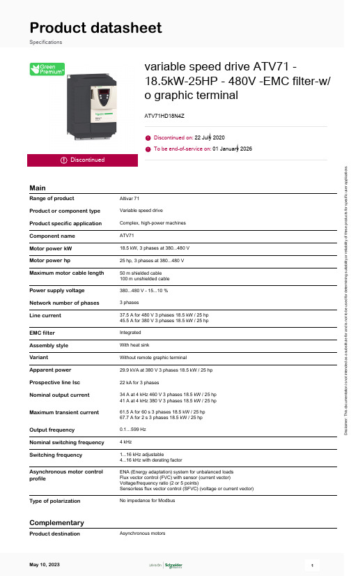
Product datasheetSpecificationsDiscontinuedvariable speed drive ATV71 -18.5kW-25HP - 480V -EMC filter-w/o graphic terminalATV71HD18N4ZDiscontinued on:22 July 2020To be end-of-service on:01 January 2026MainRange of productAltivar 71Product or component type Variable speed driveProduct specific application Complex, high-power machines Component name ATV71Motor power kW 18.5 kW, 3 phases at 380...480 V Motor power hp25 hp, 3 phases at 380...480 V Maximum motor cable length 50 m shielded cable 100 m unshielded cable Power supply voltage 380...480 V - 15...10 %Network number of phases 3 phasesLine current 37.5 A for 480 V 3 phases 18.5 kW / 25 hp 45.5 A for 380 V 3 phases 18.5 kW / 25 hp EMC filter Integrated Assembly style With heat sinkVariantWithout remote graphic terminalApparent power 29.9 kVA at 380 V 3 phases 18.5 kW / 25 hp Prospective line Isc 22 kA for 3 phasesNominal output current 34 A at 4 kHz 460 V 3 phases 18.5 kW / 25 hp 41 A at 4 kHz 380 V 3 phases 18.5 kW / 25 hp Maximum transient current 61.5 A for 60 s 3 phases 18.5 kW / 25 hp 67.7 A for 2 s 3 phases 18.5 kW / 25 hp Output frequency0.1…599 Hz Nominal switching frequency 4 kHzSwitching frequency 1...16 kHz adjustable4...16 kHz with derating factorAsynchronous motor control profileENA (Energy adaptation) system for unbalanced loads Flux vector control (FVC) with sensor (current vector)Voltage/frequency ratio (2 or 5 points)Sensorless flux vector control (SFVC) (voltage or current vector)Type of polarizationNo impedance for ModbusComplementaryProduct destination Asynchronous motorsD i s c l a i m e r : T h i s d o c u m e n t a t i o n i s n o t i n t e n d e d a s a s u b s t i t u t e f o r a n d i s n o t t o b e u s e d f o r d e t e r m i n i n g s u i t a b i l i t y o r r e l i a b i l i t y o f t h e s e p r o d u c t s f o r s p e c i f i c u s e r a p p l i c a t i o n sSynchronous motorsPower supply voltage limits323…528 VPower supply frequency50...60 Hz - 5...5 %Power supply frequency limits47.5...63 HzSpeed range1…100 for asynchronous motor in open-loop mode, without speed feedback1…1000 for asynchronous motor in closed-loop mode with encoder feedback1…50 for synchronous motor in open-loop mode, without speed feedbackSpeed accuracy+/- 0.01 % of nominal speed in closed-loop mode with encoder feedback 0.2 Tn to Tn+/- 10 % of nominal slip without speed feedback 0.2 Tn to TnTorque accuracy+/- 15 % in open-loop mode, without speed feedback+/- 5 % in closed-loop mode with encoder feedbackTransient overtorque170 % of nominal motor torque +/- 10 % for 60 s every 10 minutes220 % of nominal motor torque +/- 10 % for 2 sBraking torque<= 150 % with braking or hoist resistor30 % without braking resistorSynchronous motor controlprofileVector control without speed feedbackRegulation loop Adjustable PI regulatorMotor slip compensation Not available in voltage/frequency ratio (2 or 5 points)Automatic whatever the loadSuppressableAdjustableDiagnostic 1 LED (red) for drive voltageOutput voltage<= power supply voltageInsulation Electrical between power and controlType of cable for mounting in an enclosure With a NEMA Type1 kit: 3 wire(s)UL 508 cable at 40 °C, copper 75 °C / PVC With an IP21 or an IP31 kit: 3 wire(s)IEC cable at 40 °C, copper 70 °C / PVC Without mounting kit: 1 wire(s)IEC cable at 45 °C, copper 70 °C / PVC Without mounting kit: 1 wire(s)IEC cable at 45 °C, copper 90 °C / XLPE/EPRElectrical connection Terminal, clamping capacity: 2.5 mm², AWG 14 (AI1-/AI1+, AI2, AO1, R1A, R1B, R1C, R2A, R2B,LI1...LI6, PWR)Terminal, clamping capacity: 35 mm², AWG 2 (L1/R, L2/S, L3/T, U/T1, V/T2, W/T3, PC/-, PO, PA/+, PA,PB)Tightening torque0.6 N.m (AI1-/AI1+, AI2, AO1, R1A, R1B, R1C, R2A, R2B, LI1...LI6, PWR)5.4 N.m, 47.7 lb.in (L1/R, L2/S, L3/T, U/T1, V/T2, W/T3, PC/-, PO, PA/+, PA, PB)Supply Internal supply for reference potentiometer (1 to 10 kOhm): 10.5 V DC +/- 5 %, <10 mA, protection type:overload and short-circuit protectionInternal supply: 24 V DC (21…27 V), <200 mA, protection type: overload and short-circuit protection Analogue input number2Analogue input type AI1-/Al1+ bipolar differential voltage: +/- 10 V DC 24 V max, resolution 11 bits + signAI2 software-configurable current: 0...20 mA, impedance: 242 Ohm, resolution 11 bitsAI2 software-configurable voltage: 0...10 V DC 24 V max, impedance: 30000 Ohm, resolution 11 bitsInput sampling time2 ms +/- 0.5 ms (AI1-/Al1+) - analog input(s)2 ms +/- 0.5 ms (Al2) - analog input(s)2 ms +/- 0.5 ms (LI1...LI5) - discrete input(s)2 ms +/- 0.5 ms (LI6)if configured as logic input - discrete input(s)Response time<= 100 ms in STO (Safe Torque Off)AO1 2 ms, tolerance +/- 0.5 ms for analog output(s)R1A, R1B, R1C 7 ms, tolerance +/- 0.5 ms for discrete output(s)R2A, R2B 7 ms, tolerance +/- 0.5 ms for discrete output(s)Absolute accuracy precision+/- 0.6 % (AI1-/Al1+) for a temperature variation 60 °C+/- 0.6 % (AI2) for a temperature variation 60 °C+/- 1 % (AO1) for a temperature variation 60 °CLinearity error+/- 0.15 % of maximum value (AI1-/Al1+, AI2)+/- 0.2 % (AO1)Analogue output number1Analogue output type AO1 software-configurable logic output 10 V 20 mAAO1 software-configurable current 0...20 mA, impedance: 500 Ohm, resolution 10 bitsAO1 software-configurable voltage 0...10 V DC, impedance: 470 Ohm, resolution 10 bitsDiscrete output number2Discrete output type Configurable relay logic: (R1A, R1B, R1C) NO/NC - 100000 cyclesConfigurable relay logic: (R2A, R2B) NO - 100000 cyclesMinimum switching current3 mA at 24 V DC for configurable relay logicMaximum switching current R1, R2: 2 A at 250 V AC inductive load, cos phi = 0.4R1, R2: 2 A at 30 V DC inductive load, cos phi = 0.4R1, R2: 5 A at 250 V AC resistive load, cos phi = 1R1, R2: 5 A at 30 V DC resistive load, cos phi = 1Discrete input number7Discrete input type LI1...LI5: programmable 24 V DC with level 1 PLC, impedance: 3500 OhmLI6: switch-configurable 24 V DC with level 1 PLC, impedance: 3500 OhmLI6: switch-configurable PTC probe 0…6, impedance: 1500 OhmPWR: safety input 24 V DC, impedance: 1500 Ohm conforming to ISO 13849-1 level dDiscrete input logic Negative logic (sink) (LI1...LI5), > 16 V (state 0), < 10 V (state 1)Positive logic (source) (LI1...LI5), < 5 V (state 0), > 11 V (state 1)Negative logic (sink) (LI6)if configured as logic input, > 16 V (state 0), < 10 V (state 1)Positive logic (source) (LI6)if configured as logic input, < 5 V (state 0), > 11 V (state 1)Acceleration and deceleration ramps Linear adjustable separately from 0.01 to 9000 sAutomatic adaptation of ramp if braking capacity exceeded, by using resistor S, U or customizedBraking to standstill By DC injectionProtection type Against exceeding limit speed: driveAgainst input phase loss: driveBreak on the control circuit: driveInput phase breaks: driveLine supply overvoltage: driveLine supply undervoltage: driveOvercurrent between output phases and earth: driveOverheating protection: driveOvervoltages on the DC bus: driveShort-circuit between motor phases: driveThermal protection: driveMotor phase break: motorPower removal: motorThermal protection: motorInsulation resistance> 1 mOhm 500 V DC for 1 minute to earthFrequency resolution Analog input: 0.024/50 HzDisplay unit: 0.1 HzCommunication port protocol CANopenModbusConnector type 1 RJ45 (on front face) for Modbus1 RJ45 (on terminal) for ModbusMale SUB-D 9 on RJ45 for CANopenPhysical interface2-wire RS 485 for ModbusTransmission frame RTU for ModbusTransmission rate4800 bps, 9600 bps, 19200 bps, 38.4 Kbps for Modbus on terminal9600 bps, 19200 bps for Modbus on front face20 kbps, 50 kbps, 125 kbps, 250 kbps, 500 kbps, 1 Mbps for CANopenData format8 bits, 1 stop, even parity for Modbus on front face8 bits, odd even or no configurable parity for Modbus on terminalNumber of addresses1…127 for CANopen1…247 for ModbusMethod of access Slave CANopenMarking CEOperating position Vertical +/- 10 degreeHeight400 mmDepth213 mmWidth230 mmNet weight15 kgOption card Communication card for CC-LinkController inside programmable cardCommunication card for DeviceNetCommunication card for EtherNet/IPCommunication card for FipioI/O extension cardCommunication card for Interbus-SInterface card for encoderCommunication card for Modbus PlusCommunication card for Modbus TCPCommunication card for Modbus/Uni-TelwayOverhead crane cardCommunication card for Profibus DPCommunication card for Profibus DP V1EnvironmentNoise level60.2 dB conforming to 86/188/EECDielectric strength3535 V DC between earth and power terminals5092 V DC between control and power terminalsElectromagnetic compatibility 1.2/50 µs - 8/20 µs surge immunity test level 3 conforming to IEC 61000-4-5Conducted radio-frequency immunity test level 3 conforming to IEC 61000-4-6Electrical fast transient/burst immunity test level 4 conforming to IEC 61000-4-4Electrostatic discharge immunity test level 3 conforming to IEC 61000-4-2Radiated radio-frequency electromagnetic field immunity test level 3 conforming to IEC 61000-4-3Voltage dips and interruptions immunity test conforming to IEC 61000-4-11Standards EN 61800-3 environments 2 category C3EN/IEC 61800-3UL Type 1IEC 60721-3-3 class 3C1IEC 60721-3-3 class 3S2EN 55011 class A group 2EN 61800-3 environments 1 category C3EN/IEC 61800-5-1Product certifications ULCSANOM 117C-TickPollution degree 2 conforming to EN/IEC 61800-5-1IP degree of protection IP20 on upper part without blanking plate on cover conforming to EN/IEC 60529IP20 on upper part without blanking plate on cover conforming to EN/IEC 61800-5-1IP21 conforming to EN/IEC 60529IP21 conforming to EN/IEC 61800-5-1IP41 on upper part conforming to EN/IEC 60529IP41 on upper part conforming to EN/IEC 61800-5-1IP54 on lower part conforming to EN/IEC 60529IP54 on lower part conforming to EN/IEC 61800-5-1Vibration resistance 1 gn (f= 13…200 Hz) conforming to EN/IEC 60068-2-61.5 mm peak to peak (f= 3…13 Hz) conforming to EN/IEC 60068-2-6Shock resistance15 gn for 11 ms conforming to EN/IEC 60068-2-27Relative humidity5…95 % without condensation conforming to IEC 60068-2-35…95 % without dripping water conforming to IEC 60068-2-3Ambient air temperature for-10…50 °C (without derating)operationAmbient air temperature for-25…70 °CstorageOperating altitude<= 1000 m without derating1000...3000 m with current derating 1 % per 100 mPacking UnitsUnit Type of Package 1PCENumber of Units in Package 11Package 1 Height39.0 cmPackage 1 Width60.0 cmPackage 1 Length40.0 cmPackage 1 Weight23.8 kgUnit Type of Package 2S06Number of Units in Package 21Package 2 Height73.5 cmPackage 2 Width60.0 cmPackage 2 Length80.0 cmPackage 2 Weight36.8 kgUnit Type of Package 3P06Number of Units in Package 32Package 3 Height77.0 cmPackage 3 Width80.0 cmPackage 3 Length60.0 cmPackage 3 Weight56.1 kgOffer SustainabilitySustainable offer status Green Premium productEU RoHS Directive Pro-active compliance (Product out of EU RoHS legal scope)EU RoHS DeclarationMercury free YesChina RoHS Regulation China RoHS declarationRoHS exemption information YesEnvironmental Disclosure Product Environmental ProfileCircularity Profile End of Life InformationWEEE The product must be disposed on European Union markets following specific waste collection andnever end up in rubbish binsContractual warrantyWarranty18 monthsDimensions DrawingsVariable Speed Drives without Graphic Display TerminalDimensions without Option CardDimensions in mmDimensions with 1 Option Card (1)Dimensions in mmDimensions in in.(1) Option cards: I/O extension cards, communication cards or "Controller Inside” programmable card. Dimensions with 2 Option Cards (1)Dimensions in mmDimensions in in.(1) Option cards: I/O extension cards, communication cards or "Controller Inside” programmable card.Mounting RecommendationsDepending on the conditions in which the drive is to be used, its installation will require certain precautions and the use of appropriate accessories.Install the unit vertically:●Avoid placing it close to heating elements●Leave sufficient free space to ensure that the air required for cooling purposes can circulate from the bottom to the top of the unit. ClearanceMounting TypesType A MountingType B MountingType C MountingBy removing the protective blanking cover from the top of the drive, the degree of protection for the drive becomes IP 20.The protective blanking cover may vary according to the drive model (refer to the user guide).The protective blanking cover must be removed from ATV 71P•••N4Z drives when they are mounted in a dust and damp proof enclosure.Specific Recommendations for Mounting the Drive in an EnclosureVentilationTo ensure proper air circulation in the drive:●Fit ventilation grilles.●Ensure that there is sufficient ventilation. If there is not, install a forced ventilation unit with a filter. The openings and/or fans must provide a flow rate a●Use special filters with IP 54 protection.●Remove the blanking cover from the top of the drive.Dust and Damp Proof Metal Enclosure (IP 54)The drive must be mounted in a dust and damp proof enclosure in certain environmental conditions: dust, corrosive gases, high humidity withrisk of condensation and dripping water, splashing liquid, etc.This enables the drive to be used in an enclosure where the maximum internal temperature reaches 50°C.Three-Phase Power Supply with Upstream Breaking via ContactorA1ATV71 driveKM1ContactorL1DC chokeQ1Circuit-breakerQ2GV2 L rated at twice the nominal primary current of T1Q3GB2CB05S1, S2XB4 B or XB5 A pushbuttonsT1100 VA transformer 220 V secondary(1)Line choke (three-phase); mandatory for ATV71HC11Y…HC63Y drives (except when a special transformer is used (12-pulse)).(2)For ATV71HC40N4 drives combined with a 400 kW motor, ATV71HC50N4 and ATV71HC40Y…HC63Y, refer to the power terminal connections(3)Fault relay contacts. Used for remote signalling of the drive status.(4)Connection of the common for the logic inputs depends on the positioning of the SW1 switch. The above diagram shows the internal power supp(5)There is no PO terminal on ATV71HC11Y…HC63Y drives.(6)Optional DC choke for ATV71H•••M3, ATV71HD11M3X…HD45M3X, ATV71•075N4…•D75N4 and ATV71P•••N4Z drives. Connected in place of(7)Software-configurable current (0…20 mA) or voltage (0…10 V) analog input.(8)Reference potentiometer.All terminals are located at the bottom of the drive. Fit interference suppressors on all inductive circuits near the drive or connected on the samecircuit, such as relays, contactors, solenoid valves, fluorescent lighting, etc.Three-Phase Power Supply with Downstream Breaking via Switch DisconnectorA1ATV71 driveL1DC chokeQ1Circuit-breakerQ2Switch disconnector (Vario)(1)Line choke (three-phase), mandatory for ATV71HC11Y…HC63Y drives (except when a special transformer is used (12-pulse)).(2)For ATV71HC40N4 drives combined with a 400 kW motor, ATV71HC50N4 and ATV71HC40Y…HC63Y, refer to the power terminal connections(3)Fault relay contacts. Used for remote signalling of the drive status.(4)Connection of the common for the logic inputs depends on the positioning of the SW1 switch. The above diagram shows the internal power supp(5)There is no PO terminal on ATV71HC11Y…HC63Y drives.(6)Optional DC choke for ATV71H•••M3, ATV71HD11M3X…HD45M3X, ATV71•075N4…•D75N4 and ATV71P•••N4Z drives. Connected in place of(7)Software-configurable current (0…20 mA) or voltage (0…10 V) analog input.(8)Reference potentiometer.All terminals are located at the bottom of the drive. Fit interference suppressors on all inductive circuits near the drive or connected on the samecircuit, such as relays, contactors, solenoid valves, fluorescent lighting, etc.Three-Phase Power Supply, Low Inertia Machine, Vertical MovementA1ATV71 driveA2Preventa XPS AC safety module for monitoring emergency stops and switches. One safety module can manage the “Power Removal” function fo F1FuseL1DC chokeQ1Circuit-breakerS1Emergency stop button with 2 contactsS2XB4 B or XB5 A pushbutton(1)Power supply: 24 Vdc or Vac, 48 Vac, 115 Vac, 230 Vac.(2)S2: resets XPS AC module on power-up or after an emergency stop. ESC can be used to set external starting conditions.(3)Requests freewheel stopping of the movement and activates the “Power Removal” safety function.(4)Line choke (three-phase), mandatory for and ATV71HC11Y…HC63Y drives (except when a special transformer is used (12-pulse)).(5)The logic output can be used to signal that the machine is in a safe stop state.(6)For ATV71HC40N4 drives combined with a 400 kW motor, ATV71HC50N4 and ATV71HC40Y…HC63Y, refer to the power terminal connections(7)Fault relay contacts. Used for remote signalling of the drive status.(8)Connection of the common for the logic inputs depends on the positioning of the SW1 switch. The above diagram shows the internal power supp(9)Standardized coaxial cable, type RG174/U according to MIL-C17 or KX3B according to NF C 93-550, external diameter 2.54 mm /0.09 in., maxim(10)There is no PO terminal on ATV71HC11Y…HC63Y drives.(11)Optional DC choke for ATV71H•••M3, ATV71HD11M3X…HD45M3X, ATV71•075N4…•D75N4 and ATV71P•••N4Z drives. Connected in place of(12)Software-configurable current (0…20 mA) or voltage (0…10 V) analog input.(13)Reference potentiometer.All terminals are located at the bottom of the drive. Fit interference suppressors on all inductive circuits near the drive or connected on the samecircuit, such as relays, contactors, solenoid valves, fluorescent lighting, etc.Three-Phase Power Supply, High Inertia MachineA1ATV71 driveA2 (5)Preventa XPS ATE safety module for monitoring emergency stops and switches. One safety module can manage the "Power Removal” safety fu F1FuseL1DC chokeQ1Circuit-breakerS1Emergency stop button with 2 N/C contactsS2Run button(1)Power supply: 24 Vdc or Vac, 115 Vac, 230 Vac.(2)Requests controlled stopping of the movement and activates the “Power Removal” safety function.(3)Line choke (three-phase), mandatory for ATV71HC11Y…HC63Y drives (except when a special transformer is used (12-pulse)).(4)S2: resets XPS ATE module on power-up or after an emergency stop. ESC can be used to set external starting conditions.(5)For stopping times requiring more than 30 seconds in category 1, use a Preventa XPS AV safety module which can provide a maximum time dela(6)The logic output can be used to signal that the machine is in a safe state.(7)For ATV71HC40N4 drives combined with a 400 kW motor, ATV71HC50N4 and ATV71HC40Y…HC63Y, refer to the power terminal connections(8)Fault relay contacts. Used for remote signalling of the drive status.(9)Connection of the common for the logic inputs depends on the positioning of the SW1 switch. The above diagram shows the internal power supp(10)Standardized coaxial cable, type RG174/U according to MIL-C17 or KX3B according to NF C 93-550, external diameter 2.54 mm/0.09 in., maxim(11)Logic inputs LI1 and LI2 must be assigned to the direction of rotation: LI1 in the forward direction and LI2 in the reverse direction.(12)There is no PO terminal on ATV71HC11Y…HC63Y drives.(13)Optional DC choke for ATV71H•••M3, ATV71HD11M3X…HD45M3X, ATV71•075N4…•D75N4 and ATV71P•••N4Z drives. Connected in place of(14)Software-configurable current (0…20 mA) or voltage (0…10 V) analog input.(15)Reference potentiometer.All terminals are located at the bottom of the drive. Fit interference suppressors on all inductive circuits near the drive or connected on the samecircuit, such as relays, contactors, solenoid valves, fluorescent lighting, etc.Performance CurvesDerating CurvesThe derating curves for the drive nominal current (In) depend on the temperature, the switching frequency and the mounting type. For intermediate temperatures (e.g. 55°C), interpolate between 2 curves.X Switching frequency(1)Mounting typeRecommended replacement(s)ATV71HD18N4Z is replaced by:1x Variable speed drive, Altivar Machine ATV340, 18 kW Heavy Duty, 400 V, 3 phases ATV340D18N4。
atv71参数拷贝 -回复

atv71参数拷贝-回复什么是ATV71参数拷贝?ATV71参数拷贝是指将一个安装有Schneider Electric的ATV71变频器的应用的参数配置,通过某种方法复制到另一个ATV71变频器上的过程。
这个过程可以快速、有效地完成参数配置,避免了手动一项一项输入参数的繁琐过程。
通过参数拷贝,用户可以在多个设备上快速搭建相同的应用,提高了工作效率。
下面是一步一步回答关于ATV71参数拷贝的相关问题。
问题1:为什么需要进行ATV71参数拷贝?答:在工业领域中,往往需要在不同的设备中应用相同的参数配置。
而手动一项一项输入参数是一项繁琐且容易出错的工作。
通过参数拷贝,可以快速而准确地在多个设备上进行参数配置,提高了工作效率。
问题2:ATV71参数拷贝的具体步骤是什么?答:ATV71参数拷贝一般包括以下几个步骤:1. 连接源设备:将源设备(即参数配置已经完成或希望拷贝的ATV71变频器)与计算机或HMI(人机界面)相连接,确保设备之间能进行数据交互。
2. 备份源设备参数:使用适当的软件或工具,将源设备的参数配置备份到计算机或HMI上。
这一步骤的目的是将源设备的参数保存到本地,以便之后可以拷贝到其他设备上。
3. 连接目标设备:将目标设备(即希望将参数配置拷贝到的ATV71变频器)与计算机或HMI相连接,并确保设备之间能够进行数据交互。
4. 将备份参数拷贝到目标设备:使用相同的软件或工具,将之前备份的源设备参数配置拷贝到目标设备上。
这一步骤的目的是将之前保存的参数配置应用到目标设备上。
5. 验证参数配置:在确保参数配置已经成功拷贝到目标设备上后,使用适当的方法进行验证,确保目标设备的功能与源设备一致。
问题3:有哪些软件或工具可以进行ATV71参数配置和拷贝?答:在Schneider Electric的ATV71变频器中,有多种软件或工具可以进行参数配置和拷贝,其中包括:1. SoMove软件:SoMove是Schneider Electric为其变频器开发的一款配置和监测软件。