cvs400f
nef400数控车床说明书

nef400数控车床说明书摘要:1.Nef400 数控车床简介2.Nef400 数控车床主要特点3.Nef400 数控车床的操作方法4.Nef400 数控车床的维护保养5.安全注意事项正文:一、Nef400 数控车床简介ef400 数控车床是一款高性能的数控车床,适用于各种轴类零件的加工,具有高精度、高效率、高稳定性的特点。
该款数控车床的广泛应用,为机械加工行业带来了革命性的变革。
二、Nef400 数控车床主要特点1.高精度:Nef400 数控车床采用了先进的数控技术和高精度的测量系统,能够实现零件的精确加工,满足各种加工需求。
2.高效率:该款数控车床具有快速移动和快速换刀功能,能够大幅度提高生产效率。
3.高稳定性:Nef400 数控车床采用了优质的材料和先进的加工工艺,具有很高的结构稳定性和可靠性,能够保证长时间的稳定运行。
三、Nef400 数控车床的操作方法1.开机准备:检查数控车床的各项参数设置,确认无误后,开启数控车床。
2.程序输入:根据加工零件的图纸,编写相应的加工程序,并将其输入到数控系统中。
3.零件装夹:将待加工的零件装夹到数控车床上,并进行相应的定位和夹紧。
4.运行加工:启动数控车床,开始加工零件。
5.加工结束:加工完成后,关闭数控车床,对加工零件进行检验。
四、Nef400 数控车床的维护保养1.定期检查:对数控车床的各项功能进行定期检查,发现问题及时解决。
2.清洁保养:保持数控车床的清洁,定期进行保养,以延长设备使用寿命。
3.润滑保养:定期给数控车床的传动部位润滑,保证设备的正常运行。
五、安全注意事项1.操作人员需经过专业培训,熟悉数控车床的操作方法和安全规程。
2.加工过程中,操作人员应穿戴好劳动保护用品,确保人身安全。
3.严禁在数控车床运行过程中进行检修和调整。
菜维尔火警系统MF200 400用户手册说明书
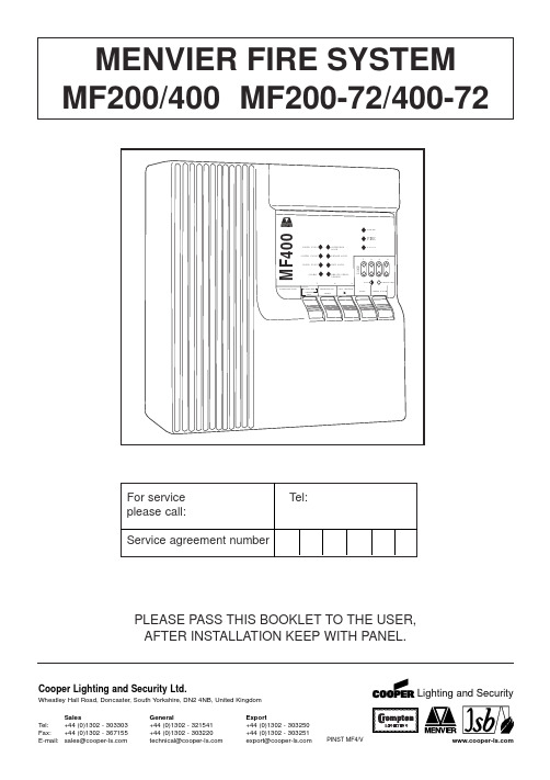
PLEASE PASS THIS BOOKLET TO THE USER,AFTER INSTALLATION KEEP WITH PANEL.MENVIER FIRE SYSTEM MF200/400 MF200-72/400-72For serviceTel:please call:Service agreement numberCooper Lighting and Security Ltd.Wheatley Hall Road, Doncaster, South Yorkshire, DN2 4NB, United Kingdom SalesGeneralExportTel:+44 (0)1302 - 303303+44 (0)1302 - 321541 +44 (0)1302 - 303250CONTENTSSERVICE SUPPORT NUMBER (1)SYSTEM INFORMATION (2)PANEL CONTROLS AND INDICATORS (3)PANEL OPERATION (4)GENERAL (4)NORMAL OPERATION (4)SUPERVISOR MODE (4)PANEL INTERFACE CONNECTIONS AND PANEL CONTROLS (6)INPUTS (6)OUTPUTS (6)FIRE CONDITION (6)WIRING DIAGRAMS (7)INSTALLATION INSTRUCTIONS (8)GENERAL (8)ADDITIONAL NOTES ON INSTALLATION FOR ELECTROMAGNETICCOMPATIBILITY(EMC) (8)INSTALLING THE PANEL (9)ROUTINE TESTING (9)FAULTS (10)FUSES (10)TECHNICAL SPECIFICATION (11)FIRE ALARM SYSTEM LOG MASTER SHEET (12)Zone No. of Call No. of Smoke No. of Heat LocationNo Points Detectors Detectors123*4*TOTAL ALARM LOAD CurrentNo of Sounders, BellsElectronicOtherDetails of system expansion:* MF400 only THIS SYSTEM HAS BEEN INSTALLED IN ACCORDANCE WITH THEREQUIREMENTS OF ..................................................STANDARDSIGNED ..................................................................... DATE .............................. FOR...........................................................................................................................THIS SYSTEM HAS BEEN COMMISSIONED IN ACCORDANCE WITH THEREQUIREMENTS OF ..................................................STANDARDSIGNED ..................................................................... DATE .............................. FOR...........................................................................................................................AudiblePiezo buzzer integral within panel, common to fire and fault.KeysThe controls of the panel are via a 5 key keyboard on the front of the panel.A key press is acknowledged by a vlip of the internal panel buzzer and in the normal mode the Supervisor Mode LED will flash.Keys labelled 1, 2 and 3 have more than one function these are described below.KEY Normal Operation Supervisor Mode Primary function Secondary function Tertiary function1Code Entry Toggle for Supervisor Mode Toggle for Supervisor Mode Disable Mode and Test Mode Disable Mode and Test Mode 2Code Entry Silence/Re-Sound Alarms Select Function-Disable or Test 3Code Entry Lamp Test/Exit (Toggle through Functions)Disable or Test 4NONERESETRESETPANEL CONTROLS AND INDICATORS Note Zones 3 & 4are not providedon MF200VisualPANEL OPERATIONGeneralThe panel has 2 levels of operation. Normal Mode and Supervisor Mode.Normal OperationSilence Buzzer (key 5)The user can silence the PANEL buzzer by pressing the 'SILENCE BUZZER' key (at any time), the buzzer will then give a beep approximately every 10 seconds.Note:-This does not silence the alarms only the panel buzzer.Supervisor Mode Entry (key 1, key 2, key 3)By entering a 4 digit access code the user will enter the Supervisor Mode. The access code is 2113. By pressing the keys in the correct order the user will see the Supervisor LED flash indicating the panel is in Supervisor Mode.Supervisor Mode Operation -Enter supervisor mode using access code 2113 prior to carrying out any of the following operations.Auto time-out of supervisor mode will occur 2 minutes after last action.RESET(key 4)Pressing 'RESET' at any time while in Supervisor Mode will reset the panel, clearing any fire, fault or Test Mode information. If a fire or fault exists the panel will re-enter the fire condition.Note:-Operating RESET will not clear disable information.Lamp Test/Exit supervisor Mode (key 3)While the supervisor LED is flashing the user can perform a lamp and buzzer test. All LED's will light and the buzzer will sound. This also exits the Supervisor Mode.Silence/Sound Alarms (key 2)While the Supervisor LED is flashing pressing 'SOUND/SILENCE' will silence or sound the alarms. If a fire is detected on another zone the alarms will re-sound.Note:-If the alarms are silenced and fire condition exists the panel buzzer will sound continuously. Disable Mode (key 1, key 2, key 3)The panel allows the supervisor to disable individual zones, both alarm lines together or the remote signal output. When any of these functions are disabled the buzzer will beep.Zones, when disabled will not be monitored for fires or faults.Alarms, when disabled will not be monitored for faults, or be activated by a fire condition.Remote signal, when disabled will not be activated by a fire condition.To disable/re-enable any of the above functions the following procedure should be followed:-1.Press 'key 1' to toggle the flashing LED from 'Supervisor Mode' to 'Disable Mode'.PANEL OPERATION - continued2.Release and repress (key 3) to toggle through LED's representing each function.3.When you highlight the LED representing each function to be enabled/disabled press'key select’to enable/disable this function.4.To exit Disable Mode and leave the panel in the disable state press 'key 1' to toggle to SupervisorMode LED and press ‘key 3’or ‘key 4’5.When a function is disabled the LED corresponding to that function will remain lit even when youexit the Disable Mode.6.To reset from Disable Mode to Normal operation, press ‘keys 2-1-1-3’, repress ‘key 3’to togglethrough LEDs to required Zone, press ‘key 2’Disable Mode LED flashing. This will extinguish in 2 minutes.Test Mode (key 1, key 2, key 3)The panel allows the supervisor to test each zone individually or any combination of zones.When a zone is put into Test Mode the buzzer will beep.Remote signal will not operate when a fire signal is received from a zone in the test mode.The operation of zones which are not in the test mode will function as normal.A fire signal from a zone in test will cause the alarms to operate for a few seconds only.To put a zone into Test Mode, the following procedure should be used:-.1.Press 'key 1' to toggle the flashing LED from 'Supervisor Mode' to 'Disable Mode' to 'Test Mode'.2.Release and repress ‘key 3’to toggle through LED's representing each zone.3.When you highlight the LED corresponding to the zone to be put into Test / taken out of Testpress 'SELECT' (key 2) to select that zone. (Zone LED lit, Test LED flashing)4.Each manual call point and detector on the zone in test can now be tested.5.When a manual call point or detector is put into a fire condition on the zone in test, the alarmswill activate for approximately 2 seconds and the zone will remain in the fire condition forapproximately 10 seconds. The panel will then automatically reset the zones, which will take approximately 10 seconds. The panel will indicate a fire signal from a zone in test by turning on the corresponding zone fire LED.6.To clear all zone fire LED's press ‘key 3’.7.To exit Test Mode and leave the panel in the test state press 'key 1' to toggle to Supervisor ModeLED and press 'Lamp Test/EXIT(key 3) or press 'RESET' (key4). Zone LED lit, Test LED lit.8.To reset from Test Mode to Normal operation, press ‘keys 2-1-1-3’, ‘key 1-1’(i.e. twice). Repress‘key 3’to toggle through LEDs to required zone, press ‘key 2’Test Mode LED flashing. This will extinguish in 2 minutes.Note:-Alarms cannot be put into test modeIf a manual call point or detector is left in a fire condition on a zone in test, the panel will carry out step 5 until the fire signal is cleared.Operating 'RESET' will not clear test information. Test information is only lost when the mains supply and battery are disconnected or the function is re-enabled.PANEL INTERFACE CONNECTIONS AND INTERFACE CONTROLSInputsClass ChangeA pair of terminals are provided for class change. By shorting these terminals together (e.g. switch, time clock) the alarms will sound. The panel will not indicate a fire. The alarms will cancel when the short circuit is removed. If the short circuit is not removed the Alarms will NOT cancel.WARNING:- NO VOLTAGE SHOULD BE APPLIED TO THIS INPUT.ZonesMF400 provides 4 zones & MF200 provides 2 zones . The maximum number of detectors per zone line is 20 and end of line resistors must be fitted for correct operation.Manual call points used in the system are polarised. Use the connection details accompanying the call points to ensure the correct polarity is used, using the terminal marked '9300'.Detectors used in the system are polarised 24V Menvier detectors. They must be wired in accordance with instructions accompanying the detector. Use the terminal marked '9300'.OutputsAuxiliary DC OutputA24Vdc output is provided. This output is protected by a fuse which is monitored for rupture. This output can be to used to power fire or fault auxiliary equipment. Equipment must be connect to this output so that current will only be drawn from this output when a fire condition exists or when no fault exists.WARNING:-DO NOT EXCEED THE RATED OUTPUT CURRENTAuxiliary Fault OutputThis is a 'solid state' semiconductor switch which is normally operated with no fault present and de-activates when the panel detects a fault. It operates by providing 24Vdc which can be connected directly to a 24V auxiliary device (e.g. relay) and a pull down switch to 0V. It is current limited to10mA.Remote Signal Output (Auxiliary Fire Output)This is a 'solid state' semiconductor switch which operates when the panel detects a fire. It operates by providing 24Vdc which can be connected directly to a 24V auxiliary device (e.g. relay) and a pull down switch to 0V. It is current limited to 10mA. 'Class Change' and 'Sound/Silence' do not operate this output.AlarmsAlarm outputs are provided. ONLY polarised and suppressed equipment should be used.Ensure the polarity of the connections are observed at all times and end of line resistors are fitted for correct operation.The maximum alarm load is specified in the Technical Specification section.Alarm devices should be spread equally across the 2 alarm circuits.WARNING:-DO NOT EXCEED THE RATED OUTPUT CURRENT.Options included within this panel which are not required by EN54 are, Class Change, Remote Signal Output and Auxiliary DC output. These options cannot be used to simulate options with requirements within EN54.FIRE CONDITIONIf the panel receives a fire signal from a manual call point or detector the red fire LED will light, the panel buzzer will sound, the alarm devices will be activated and the remote signal will also activate. The red zone fire LED will light corresponding to the zone in fire. Any new zone in a fire condition will light.WIRING DIAGRAMS22K O h mA U X F A U L T A N D R E M O T E S I G N A L C O N N E C T I O N SINSTALLATION INSTRUCTIONSGeneralAll cables entering the panel must be via the cable entries provided or the aperture in the rear face. All cables must be tested for earth fault before connecting to the panel. Do not use a High Voltage Tester (Megger) on any cable after connection to any equipment including the panel.The wiring of each zone, interface control or alarm line should be in a 2 core cable.The total cable resistance for each zone must not exceed 85ohm.Any voltage drop on alarm line cables will affect the sound level of alarm devices and should be kept to a minimum.The Cable used for alarm devices must be of a type suitable for protection against fire for at least 30 minutes. The Extra Low voltage unscreened cables must be segregated from the mains cables. Please refer to BS 5839 part 1 1988 for more details.For zones and alarms the end of line resistor must be fitted to the end of the circuit. No 'spurs' shall be used.If a zone is not to be used the end of line resistor should be fitted in the corresponding zone terminal block between '+' and '-'.A cable screen termination for each panel interface is provided. The cable screen of any zone, interface control or alarm line should be connected directly to the corresponding terminal marked 'E'. Additional Notes On Installation For Electromagnetic Compatibility (EMC)When used as intended this product complies with EMC Directive (89/336/EEC) and the UK EMC regulations 1992 (SI 2372/1992) by meeting the limits set by the standards EN61000-3-2 1994,EN50081-1 1992 and EN50130-4 1996. The following installation guidelines must be followed:1. External cables must be connected using the cable entries or knockouts provided.2. When routing external cables inside the product they must bea) kept as short as possible.b) routed close to the metal back box.c) kept as far as possible from the electronics.Any modifications other than those in the main installation leaflet, or any other use of the product may cause interference & is the responsibility of the user, who should ensure compliance with the EMC & low Voltage directives.BatteryconnectionsInstalling the PanelRead all the installation instructions before commencing with the installation.Installation of this panel must be done by a suitably qualified/trained person. The installation must comply with IEE wiring regulations and with BS5839 part 1 1988.The electronic components within the Fire Panel are Static Sensitive. Do not touch the electronic components directly.1.Remove the front cover.2.Fix the metal back box to the wall using the 3 fixing holes. No 8 screws (or similar size) arerecommended.3.Interface cables may be connected into the panel either via the back cable entry slot or throughthe top cable entries, fit the plastic blanking plugs to any unused holes.4.The mains supply should be exclusive to the panel and double pole isolating switch should beprovided and clearly labeled 'FIRE SYSTEM- DO NOT SWITCH OFF.' (See BS5839 part 1 1988) Mains cable should only enter the panel via the top or bottom left cable entries.5.Connect the mains cable to the Mains input terminal block. Connect Earth to the terminal marked(E), Neutral to the terminal marked (N) and Live to the terminal marked (L). DO NOT TURN ON THE MAINS SUPPLY TO THE PANEL.6.Connect the battery connectors to the battery. Connect the RED wire to the battery terminalmarked RED (+). Connect the BLACK wire to the battery terminal marked BLACK (-). Ensure the wires are routed away from the switches.7.When power is first supplied, the Panel Buzzer will sound and all the LED Indicators will light forapproximately 2 seconds. Only the green power LED should be ON. After a few seconds the Fault and Power fault LED's will flash and the buzzer will beep to indicate no mains is present on the panel. (Other fault Indicators may be flashing at this stage). If the System Fault LED is lit and the buzzer is on continuously, remove the (+) battery connection and follow step (6) again.8.Connect the front cover to the panel by locating the bottom clips in their slots and fixing the anti-tamper screw located on top of the panel. CAUTION ELECTRIC SHOCK HAZARD :- BEFORE TURNING ON THE MAINS SUPPLY THE PANEL COVER MUST BE FITTED.9.Turn on the mains supply to the panel. The Power fault Indication should stop after a fewseconds.10.Carry out testing of the system.11.Manual call points should be individually tested for correct operation.12.Each detector should be tested.13.If any Auxiliary outputs are used or the Class Change input is used these should also be testedfor correct operation.14.Check all alarm devices work correctly.15.Details of the Fire Alarm installation should be made in this Instruction Booklet (page 2).16.Fill in the zone Identification Label and display clearly on or next to the panel.17. Pass all the documentation over to the end user.Maintenance should be carried out at regular intervals. Daily, Weekly, Quarterly and Yearly tests should be carried out. Detailed below is a summary of the Daily and Weekly tests. For full details of all the tests please refer to BS5839 Part 1 1988.Daily attention by the user•The panel indicates normal operation. If a fault is displayed it should be recorded in the log bookand reported to the service organisation.•That any faults from the previous day have received attention.Weekly attention by the user•At least one detector or call point per week is operated for correct operation, choosing a differentzone each week. The Panel should register this fire signal and the alarms and any ancillary equipment should operate•The Panel indication should be checked by pressing 'Lamptest/Exit'(key3) while in thesupervisor mode.•Any defects should be recorded in the log book and corrective action taken as soon as possible.INSTALLATION INSTRUCTIONS - continuedROUTINE TESTINGFAULTSGeneralAll fault conditions on the fire panel will be indicated by the 'FAULT' LED flashing, the panel buzzer beeping and at least one other fault specific LED flashing. The auxiliary fault output will de-activate. All faults indications will be cleared automatically if the fault is removed unless stated.CAUTION ELECTRIC SHOCK HAZARD :- BEFORE REMOVING THE PANEL COVER THE MAINS SUPPLY MUST BE TURNED OFF.Specific Fault Indication Fault/ActionPower Fault LED Flashing The 240V Mains supply, battery standby supply, battery charger andall the fuses are monitored for faults.Check the battery is connected to the charger correctly. Check theMains supply is switched on. Check the fuses for rupturesPower LED Flashing The Fire Panel internal power supplies are monitored for faults.Check 240V Mains supply is turned on. Check the fuses for ruptures.If the problem persists contact your service company.Zone(s) Fault LED Flashing The zone lines are monitored for open circuit, short circuit anddetector removed.Check the wiring for open circuits and short circuits. All detectors inthe system must be correctly fitted to the detector bases. Ensure theend of line resistors are correctly connected. If all the zone faultLED's are lit pressing 'RESET' whilst in the Supervisor Mode willclear this fault Indication.Alarm Fault LED Flashing This fault should be investigated immediately as it should beassumed the alarms are not operational. Each alarm line is monitoredfor open circuit and short circuit. The alarm line fuses are alsomonitored for ruptures. Exceeding rated Alarm and Aux DC load maycause internal power faults. If the Alarm lines switch off shortly afteroperation check for alarm line over-load. Press 'RESET' whilst inSupervisor mode to clear the fault indication.Check the wiring for open circuits and short circuits Ensure the end ofline resistors are correctly connected. Check the fuses for ruptures. Earth Fault LED Flashing The Fire Panel will indicate an earth fault if any connection to earthexists in any wiring connected to the panel, other than the Mainssupply Safety Earth. This could be caused if the any wiring insulationis broken, or ancillary equipment connected to the panel has a nonsafety earth connection. If the fault persists contact your servicecompany.System Fault LED on The Micro controller has a supervisor circuit monitoring it for correctoperation and has detected either a software or hardware fault. Toclear this fault indication press 'RESET' whilst in the SupervisorMode. If this fault persists contact your service company.Alarm 1 (1A 250V)Aux DC (250mA 250V) Alarm 2 (1A 250V)Note.All fuses are glass20mm quick blowBattery (5A 250V)TECHNICAL SPECStandards Design to comply with EN54 Part 4 1996 and Part 21996Electromagnetic Compatibility EN 50130-4 1996Alarm Systems Part 4 EN50081-1 1992EN61000-2-2-1994Number of Zones4(MF400) 2(MF200)Number of alarm Lines2Mains Input Voltage240Vac +10%-15%Standby Duration24HrSystem operating Voltage24Vdc NominalIndicatorsFire High intensity red Light Emitting Indicators (LED)Fault High intensity yellow LED'sPower High intensity green LEDFault IndicationsZones Open and short circuit, detector removedAlarms Open and short circuitPower Mains fail, battery fault, battery charge fault. All fuses aremonitored.Earth Fault Any Earth connection to low voltage systemSystem Fault Micro contoller faultEnd of Line ElementsZones22kohmAlarms22kohmMaximum No of detectors per zone 20 (24V-30µA each)Maximum Alarm Load750mA24VdcAuxiliary DC Output32mA24Vdc (Up to 100mA at the expense of Alarm Load) Auxiliary Fault Output24Vdc pull to 0V. Maximum 10mARemote Signal Output24Vdc pull to 0V. Maximum 10mAStandby Power source (Battery) One Valve Regulated (Absorption Type) Lead Acid12V Battery Recommenced replacement period 4years. Capacity 4AH (24Hr Standby) 7AH(72Hr standby) Max current draw is 3A resistive.Battery Recharge Period48HrsTerminal Connector Capacity0.5mm2to 2.5mm2Dimensions300mm X 300mm X 74mmPanel Weight (Mass)24Hr 4.8kg, 72Hr 6.0KgPanel operating temperature-5°C to +40°C Humidity 75% (Non Condensing)PAGE 11F I R E A L A R M S Y S T E M L OG - PH O T O C O P Y T HI S S H E E T I t i s r e c o m m e n d e d t h a t t h i s b o o k i s m a i n t a i n e d b y a r e s p o n s i b l e e x e c u t i v e a n d t h a t e v e r y ‘e v e n t ’a f f e c t i n g t h e i n s t a l l a t i o n s h o u l d b e r e c o r d e d . A n ‘e v e n t ’s h o u l d i n c l u d e f a l s e a l a r m s , f a i l u r e s , t e st s , t e m p o r a r y d i s c o n n e c t i o n s , t h e d a t e s o f i n s t a l l i n g e n g i n e e r ’s v i s i t s a n d a n o t e o f a n y o u t s t a n d i n g w o r k o r c o n d i t i o n s .。
RP40-FR系列宽输入范围DC DC转换器商品说明书
RP40-11012DFR/P RP40-11024DFR/N-HC RP40-2405SFR/P RP40-2412SFR/N-HCRP40-4805SFR/P-HCFeaturesRegulated Converters• Wide 4:1 Input Voltage Range• 1.6kVDC Isolation for 24Vin and 48Vin, 3kVDC Isolation for 110Vin • Efficiency up to 92%• Six-Sided Continuous Shield• UL60950-1 AM2 Certified, EN50155 CertifiedPD-1REV.: 0/2016DC/DC Converter3 YE A Rw ar r a n t y3DescriptionThe RP40-FR series wide range input DC/DC converters have been especially designed for railway applications and are EN50155 certified. They are also pending to UL60950-1 and cUL 60950-1, this makes them ideal for all high input voltage telecom and industrial applications where approved safety standards are required.40 Watt2“ x 1“Single & Dual OutputRP40-FR Selection GuidePart Number Input Output Output Input (1) Efficiency (1)Max. Capacitive Voltage Range Voltage Current Current typ. Load (2) [VDC] [VDC] [mA] [mA] [%] [µF]RP40-243.3SFR (3,4)9-36 3.3 10000 1528 90 26600RP40-2405SFR (3,4) 9-36 5 8000 1832 91 20000RP40-2412SFR (3,4)9-36 12 3333 1811 92 3900RP40-2415SFR (3,4) 9-36 15 2666 1811 92 2600RP40-2424SFR (3,4)9-36 24 1666 1831 91 1300RP40-483.3SFR (3,4) 18-75 3.3 10000 764 90 26600RP40-4805SFR (3,4)18-75 5 8000 916 91 20000RP40-4812SFR (3,4) 18-75 12 3333 906 92 3900RP40-4815SFR (3,4)18-75 15 2666 906 92 2600RP40-4824SFR (3,4) 18-75 24 1666 915 91 1300 RP40-1103.3SFR (3,4) 43-160 3.3 10000 341 88 26600RP40-11005SFR (3,4) 43-160 5 8000 409 89 20000RP40-11012SFR (3,4)43-160 12 3333 402 90.5 3900RP40-11015SFR (3,4) 43-160 15 2666 400 91 2600RP40-11024SFR (3,4)43-160 24 1666 404 90 1300RP40-2412DFR (3,4) 9-36 ±12 ±1666 926 90 ±2600RP40-2415DFR (3,4)9-36 ±15 ±1333 926 90 ±1600RP40-2424DFR (3,4) 9-36 ±24 ±833 915 91 ±650RP40-4812DFR (3,4) 18-75 ±12 ±1666 463 90 ±2600RP40-4815DFR (3,4) 18-75 ±15 ±1333 370 90 ±1600RP40-4824DFR (3,4)18-75 ±24 ±833 286 91 ±650RP40-11012DFR (3,4) 43-160 ±12 ±1666 204 89 ±2600RP40-11015DFR (3,4) 43-160 ±15 ±1333 204 89 ±1600RP40-11024DFR (3,4)43-160 ±24 ±833 200 91 ±650Model NumberingOrdering ExamplesRP40-2405SFR/P = 24V Input, 5V Output, Positive Logic CTRL pin and Trim pin fitted RP40-2415SFR/N = 24V Input, 15V Output, Negative Logic CTRL pin and Trim pin fitted Input Voltage Output Voltage S ingle or D ualRP40-__ __ _FR/_ _Notes:Note1: Values at nominal input voltage and full load Note2: Test by minimum Vin and constant resistor load.EN50155 Certified UL60950-1 AM2 CertifiedE196683Notes:Note3: standard part is with suffix “P” for positive logic (1=ON, 0=OFF) and trim pin or add suffix “N” instead for negative logic (0=ON, 1=OFF) and trim pin Note4: add suffix “-HC” for premounted Heat-sink with clampsPackage (4)CTRL Logic (3)PD-2REV.: 0/2016DC/DC Conver terRP40-FRSeriesSpecifications (measured @ ta = 25°C, nominal input voltage, full load otherwise noted)DC/DC Conver terSpecifications (measured @ ta = 25°C, nominal input voltage, full load otherwise noted)REGULATIONSParameterConditionValueOutput Voltage Accuracy full load and nominal Vin±1%Voltage Adjustability Single3.3Vout, 5 Vout, 12Vout 15Vout, 24Vout ±10%-10% to +20%Line Voltage Regulation low line to high line at full load ±0.2%Load Voltage Regulation 0% to 100% loadSingle Dual±0.5%±1.0%Cross Regulationasymmetrical 25%<>100% load±5%Transient Response recovery time25% load step change 250µs typ.continued on next pageRP40-FRSeriesPD-3REV.: 0/PD-4REV.: 0/2016DC/DC Conver terSpecifications (measured @ ta = 25°C, nominal input voltage, full load otherwise noted)RP40-FRSeriesDC/DC Conver terSpecifications (measured @ ta = 25°C, nominal input voltage, full load otherwise noted)RP40-FRSeriesPD-5REV.: 0/ Trim up 12345678910%Vout =15.1515.315.4515.6015.7515.9016.0516.2016.3516.50Volts R U = 419.81199.91126.6089.9567.9653.3042.8334.9828.8723.98KOhms Trim up 11121314151617181920%Vout = 16.65016.80016.95017.10017.25017.40017.55017.70017.85018.000Volts R U = 19.9816.6513.8311.429.327.49 5.87 4.43 3.15 1.99KOhms Trim down 12345678910%Vout = 14.85014.70014.55014.40014.25014.00013.75013.50013.25013.000Volts R D =284.89128.6876.6150.5834.9624.5517.1111.537.193.72KOhmsTrim up 12345678910%Vout =24.24024.48024.72024.96025.20025.44025.68025.92026.16026.400Volts R U = 1275.2606.60383.73272.30205.44160.87129.03105.1586.5871.72KOhms Trim up 11121314151617181920%Vout = 26.64026.88027.12027.36027.60027.84028.08028.32028.56028.800Volts R U = 59.5649.4340.8633.5127.1521.5716.6612.298.38 4.86KOhms Trim down 12345678910%Vout = 23.76023.52023.28023.04022.80022.56022.32022.08021.84021.600Volts R D =838.15376.78222.98146.0999.9569.1947.2230.7417.937.68KOhmsRP40-xx15SFRRP40-xx24SFRPROTECTIONSParameterCondition ValueShort Circuit Protection (SCP)continuous, automatic recoveryOver Voltage Protection (OVP)Zener Diode Clamp 3.3Vout 5Vout12Vout15Vout 24Vout3.9VDC 6.2VDC 15VDC 20VDC 30VDCOver Load Protection (OLP)% Iout rated150% typ., Hiccup ModeOver Temperature Protection (OTP)115°C Isolation Voltage24Vin, 48VinI/P to O/PI/P to O/P to Case 1.6kVDC 1.6kVDC 110VinI/P to O/PI/P to O/P to Case3kVDC 1.6kVDC Isolation Resistance 500VDC1G Ω min.Isolation Capacitance1500pF max.Notes:Note6: This power module is not internally fused. An input line fuse must always be used.SAFETY AND CERTIFICATIONSCertificate Type (Safety)Report / File NumberStandard Information Technology Equipment, General Requirements for Safety E196683UL60950-1, 2nd Edition AM:2, 2014CSA C22.2 No. 60950-1-07Railway Applications - Electrical Equipment used on rolling stock15A100702E-CEN50155, 2007EMI ComplianceConditionStandard / CriterionIndustrial, scientific and medical equipment - Radio frequency disturbance characteristics - Limits and methods of measurement (8)with external filter EN50121-3-2, Class A EN55011, Class A or B ESD Electrostatic discharge immunity testRadiated, radio-frequency, electromagnetic field immunity test Fast Transient and Burst Immunity (9)Surge Immunity (9)Immunity to conducted disturbances, induced by radio-frequency fields Power Magnetic Field ImmunityAir ±8kV and Contact ±6kV20 V/m ±2kV ±2kV 10 Vr.m.s100A/m continuous; 1000A/m 1sEN61000-4-2, Criteria A EN61000-4-3, Criteria A EN61000-4-4, Criteria A EN61000-4-5, Criteria A EN61000-4-6, Criteria A EN61000-4-8, Criteria Acontinued on next pagePD-6REV.: 0/2016DC/DC Conver terSpecifications (measured @ ta = 25°C, nominal input voltage, full load otherwise noted)RP40-FRSeriesDC/DC Conver terSpecifications (measured @ ta = 25°C, nominal input voltage, full load otherwise noted)RP40-FRSeriesPD-7REV.: 0/2016PD-8REV.: 0/2016DC/DC Conver terSpecifications (measured @ ta = 25°C, nominal input voltage, full load otherwise noted)RP40-FRSeriesDC/DC Conver terSpecifications (measured @ ta = 25°C, nominal input voltage, full load otherwise noted)RP40-FR SeriesPD-9REV.: 0/2016 Specifications (measured @ ta = 25°C, nominal input voltage, full load otherwise noted)DIMENSIONS and PHYSICAL CHARACTERISTICSParameter Type ValueMaterialCaseBasePottingCopper Alloy CuZn33FR4 PCBSilicone (UL94V-0)Packaging Dimension (LxWxH)without Heat-sinkwith Heat-sink50.8 x 25.4 x 10.2mm56.8 x 25.4 x 16.8mmPackaging Weightwithout Heat-sinkwith Heat-sink32g43g continued on next pagePD-10REV.: 0/PACKAGING INFORMATIONParameterTypeValuePackaging Quantity without Heat-sink with Heat-sink Tube Tray9pcs 20pcsStorage Temperature Range -55°C to +125°C Storage Humidity5% - 95% RHThe product information and specifications are subject to change without prior notice. RECOM products are not authorized for use in safety-critical applications (such as life support) without RECOM’s explicit written consent. A safety-critical application is defined as an application where a failure of a RECOM product may reasonably be expected to endanger or cause loss of life, inflict bodily harm or damage property. The buyer shall indemnify and hold harmless RECOM, its affiliated companies and its representatives against any damage claims in connection with the unauthorized use of RECOM products in such safety-critical applications.25.4Specifications (measured @ ta = 25°C, nominal input voltage, full load otherwise noted)PD-11REV.: 0/RP40-4815SFR/N RP40-4815SFR/N-RP40-483.3SFR/NHCRP40-11012DFR/P RP40-11024DFR/N-HC RP40-2405SFR/P RP40-2412SFR/N-HCRP40-4805SFR/P-HC。
ZERO 点胶机操作手册-2020 2000 3000 4000通用版

8.1. 單點點膠 Dispense Dot ............................................................................................................................16 8.2. 線段開始 Line Start ...................................................................................................................................16 8.3. 線段中間點 Line Passing ..........................................................................................................................16 8.4. 圓形點膠中心點 Circle.............................................................................................................................16 8.5. 圓弧中點 Arc Point....................................................................................................................................16 8.6. 線段點膠結束點 Line End .......................................................................................................................17 8.7. 程式終點 End Program..............................................................................................................................17 8.8. 出膠機開關 Dispense On / Off .................................................................................................................17 8.9. 執行指定位址 Goto Address ....................................................................................................................17 8.10. 陣列點膠 Step & Repeat..........................................................................................................................18 8.11. 區域塗佈設定 Brush Area ......................................................................................................................21 8.12. 呼叫副程式 Call Subroutine....................................................................................................................25 8.13. 執行特定程式組別 Call Program ..........................................................................................................27 8.14. 設定輸入及輸出 Set I/O..........................................................................................................................27 8.15. 等待點設定 Wait Point.............................................................................................................................28 8.16. 暫停點 Stop Point......................................................................................................................................28 8.17. 原點設置 Home Point...............................................................................................................................28 8.18. 迴圈位置設定 Loop Address ................................................................................................... ...............28 8.19. 空點 Dunny Point ....................................................................................................... .............................28 8.20. 回機械原點 Initialize................................................................................................................................28 8.21. 標記設定 Lable .........................................................................................................................................29 8.22. 顯示次數 Display Counter........................................................................................................................29
配电箱元器件符号
1.CVS400F-3P-400A/ NSX400F/3P MIC2.3;NSX/CVS表示施耐德的CVS 、NSX系列塑壳开关,400表示额定电流400A,F表示开断电流为36KA(分断等级:36KA,50KA,70KA,100KA,150KA),3P表示三极;Mic 2.3表示三段式电流保护。
断路器NSX400H MIC5.2A 315:“NSX”施耐德品牌塑壳断路器“400”表示壳架电流400A“H”表示分断能力为70KA,“MIC5.2A”表示脱扣单元型号:三段保护+电流表,“315”表示额定电流为315A2.INS400:施耐德负荷开关3极400A的负荷隔离开关3.WEFPT-*FB:施耐德电气火灾监测器4.C65N-3P-16A:C65N-63为施耐德的型号,3p表示三相空开,16A表示额定电流为16A5.CJR3-25/U:热继电器,CJR是型号,额定电流为25安;CJ3-18是交流接触器,CJ3是型号,额定电流为18安.6.断路器中的额定电流,长延时电流,短延时电流,瞬时脱扣电流:额定电流是断路器标称电流。
长延时电流,短延时电流,瞬时脱扣电流也3段保护,也就是过载长延时,短路短延时,短路瞬动。
短路短延时保护能起到防越级跳闸的功能;当F点短路时,只有靠近F点的QF2断路器动作,而上方位的QF1断路器不动作,这就是选择性保护(由于QF1不动作,就使未发生故障的QF3、QF4支路保持供电)。
如果QF2和QF1都是A类断路器,则F点发生短路,短路电流值达一定值时,QF1、QF2同时动作,QF1断路器回路及其下的支路全部停电,就不是选择性保护了。
断路器中的额定电流是断路器可以长期通过的正常电流;长延时电流:是断路器中通过的过负荷电流;短延时电流:是继电保护按时段跳闸保护的短路电流;瞬时脱扣电流:是断路器控制线路或设备的最大短路电流7.交流接触器:供远距离接通和分断电路、频繁地起动和控制交流电动机之用,并可与适当的热继电器组成电磁起动器以保护可能发生操作过负荷的电路。
SF400 千兆以太网适配器用户手册说明书

北京网迅科技有限公司SF400千兆以太网适配器用户手册版权声明本手册所有内容,其版权属于北京网迅科技有限公司(以下简称北京网迅)所有,未经北京网迅许可,任何单位和个人不得仿制,拷贝,转译或者任意引用。
版权所有 不得翻印文件更改历史记录初始信息文件名称 SF400 千兆以太网适配器用户手册初始版本号 V1.00 发布日期 2019.11编写人 章圣表 批准人 杨友华更改记录版本号 更改要点 修改人 批准人批准发布日期 V1.00 初始版本 章圣表 杨友华 2019.11.22 V1.01 操作系统支持章节修改 章圣表 杨友华 2020.6.1 V1.02 操作系统支持章节修改 章圣表 杨友华 2020.7.3 V1.03 修改WOL和NCSI描述 章圣表 杨友华 2021.1.7V1.04 更新了SF400的产品图片,PCB版本从1.03升级到1.04版本。
章圣表 杨友华 2021.6.1V1.05 修改产品型号,军用工作温度范围修改。
章圣表 杨友华 2021.6.23第1章 SF400千兆以太网网络适配器简介SF400千兆以太网网络适配器基于北京网迅科技有限公司自主设计的千兆以太网控制器芯片,拥有自主知识产权,它能满足企业数据中心对网络最新需求,应用在服务器上,支持管理程序分流数据排序功能,通过有效地平衡网络负载在CPU核上,提高数据吞吐量和CPU使用率,在多CPU处理器系统中表现出极佳的性能。
SF400千兆以太网网络适配器具有优良的抗噪声能力,支持100米距离网线连接,适用于服务器和高端设备,它可轻松将任何PCI Express 集成到千兆网络中,并且对性能进行了优化,使系统I/O不再是高端网络应用的瓶颈。
SF400千兆以太网网络适配器集成以太网MAC+PHY(媒体接入控制器和物理接口收发器),在千兆位以太网连接中最高时可同时允许四个端口以全双工的工作模式工作以适应高性能网络通信,既可以通过链路聚合扩展带宽又可以节约PCI Express通道资源,同时不会占用总线带宽。
施耐德cvs100f说明书

EasyPact CVS100-250Circuit breaker/Switch-disconnector Disjoncteur/Interrupteur-sectionneurInterruptor automático/Interruptor seccionador 断路器/隔离开关Leistungsschalter/LasttrennschalterInterruttore automatico/interruttore-sezionatore Disjuntor/Interruptor-seccionador Выключатель/РазъединительREMARQUE IMPORTANTEL’installation, l’utilisation, la réparation et la maintenance des équipements électriques doivent être assurésuniquement par du personnel qualifié. Schneider Electric décline toute responsabilité quant auxconséquences de l’utilisation de ce matériel.PLEASE NOTEElectrical equipment should be installed, operated, serviced, and maintained only by qualified personnel.No responsibility is assumed by Schneider Electric for anyconsequences arising out of the use of this material.TENGA EN CUENTALa instalación, manejo, puesta en servicio y mantenimiento de equipos eléctricos deberán ser realizados sólo por personal cualificado.Schneider Electric no se hace responsable de ninguna de las consecuencias del uso de este material.BITTE BEACHTENElektrische Geräte dürfen nur von Fachpersonal installiert, betrieben, bedient und gewartet werden. Schneider Electric haftet nicht für Schäden, die durch die Verwendung dieses Materials entstehen.NOTAManutenzione, riparazione, installazione e uso delle apparecchiature elettriche si devono affidare solo a personale qualificato.Schneider Electric non si assume alcuna responsabilità per qualsiasi conseguenza derivante dall’uso di questo materiale.NOTAA instalação, utilização e manutenção do equipamento eléctrico devem ser efectuadas exclusivamente por pessoal qualificado.A Schneider Electric não assume qualquer responsabilidade pelas consequências resultantes da utilização deste material.请注意电气设备的安装、操作、维修和维护工作仅限于合格人员执行。
IFR 400紧凑型火焰探测器操作手册说明书

IFR 400Content1.1 Generalaspects1.1 Introduction1.2 Warningnotes1.3 Copyrightprotection1.4 Disposalinformation1.5 Warranty1.6 Obligation of the operating company1.7 Liabilitydisclaimer1.8 Declarationofconformity1.9 Address of the manufacturer2 Safety2.1 Intendeduse2.2 Requirements on persons2.3 Safetyinstructions2.4Safetydevices2.4.1Fundamentalaspects2.4.2 Safety devices on the compactindustrial flame controller IFR 4002.5 Safety instructions in case of maintenanceand troubleshooting2.5.1 Fundamental aspects2.5.2 Electrical / electronic devices2.5.3 Testing per German Workplace SafetyOrdinance (BetrSichV)2.5.4 Safety test3 Technical data3.1 General characteristic features3.2 Electrical system, optical system, mechanical system 3.3 Weight3.4 Dimensions3.5 Block diagram IFR 4004 Transport, installation and connection4.1 Scope of delivery4.2 Packaging4.3 Shipping instructions4.4 Dimensions IFR 4004.5 Installation4.6 Connection4.6.1 Electrical connection4.6.2 Connection diagram IFR 4004.7 Storage4 4 45 5 5 567 78 8 89 9 9 10 10 10 11 11 12 12 12 13 13 13 14 14 14 14 15 15 16 16 1616Content5 Description5.1 Functional description IFR 4006 Operation of the compact flame detector IFR 400 6.1 Test of the compact flame detector6.2 Operating indicator LED7 Maintenance and servicing7.1 Cleaning8 Troubleshooting9 Order data10 Accessories 17 17 17 17 17 18 18 18 19 191 | General aspects1.1 IntroductionThis operating manual is a helpful guide for ensuring the successful and safe operation of the compact flame detector IFR 400. They contain important information on how to operate the system safely, correctly and efficiently. Observing the operating manual will help to prevent hazards, reduce cost of repairs and downtime and increase the reliability and life of the device. All illustrations and drawings in this operating manual are shown for illustration purposes and do not contain details for design.The operating manual always has to be accessible at the device. They must be read and ap-plied by each person who is required to work with/on the device.This work may involve, for example:• operation• troubleshooting during operation• servicing• maintenance (upkeep, inspection, repair) and/or• transportThis should be confirmed by the operating company in writing.1.2 Warning notesThe following warning notes are used in these operating instructions:pany this warning to prevent the risk of death and severe personal injury.This warning level indicates potential damage to property. If this situation is not prevented, it may result in damage to property. Follow the instructions that accompany this warning to prevent damage to property.NOTICEA notice indicates additional information that will make the handling of the device easier.1.3 Copyright protectionThis operating manual has to be treated as confidential. They may only be used by authorised staff. Access by third parties may only be granted upon written agreement of BST Solutions. All documents are protected in keeping with the German copyright law.The disclosure and reproduction of documentation, in whole or in part, as well as the ex-ploitation and communication of its content shall not be permitted unless expressly stated otherwise. Offenders are liable for prosecution and the payment of damages.We reserve all rights to exercise industrial property rights.1.4 Disposal informationThe compact flame detector is equipped with electrical and electronic compo-nents and must be disposed separate from household waste. Follow the localand actual regulations for waste disposal.1.5 WarrantyRead these operating instructions carefully and in full before operating the compact flame detector IFR 400!The manufacturer is not liable for damage or operating malfunctions that result from the operating manual not being observed.The operating company has to supplement the operating manual with operating instructions on the basis of national regulations on accident prevention and environmental protection, including information on supervision and notification requirements with respect to special operating circumstances, e.g. regarding organisation of work, working processes and staff deployed.The recognised technical rules for safe and professional working also have to be observed in addition to the operating manual and the regulations on accident prevention applicable to the country and place of use.The warranty shall become void, for example, in the event of:• inappropriate use• use of impermissible equipment• incorrect connection• prior works that are not part of the supplied product or service• use of non-original spares and accessories• conversion, if this has not been approved by BST Solutions• non-performance of specified maintenance work1.6 Obligation of the operating companyThe Industrial Flame Controller IFR 400 may cause hazards if it is operated inappropriately or in an improper condition.The operating company is under the obligation to operate the machine in its intended stateonly. The operating company must secure hazardous areas that exist between BST Solutions devices and the customer‘s own equipment.The operating company must appoint and instruct responsible staff:• O nly deploy trained or instructed staff.• C learly set out the responsibilities of the staff with regard to operation, set-up, maintenan-ce and repair.• R egularly check that staff are safety conscious and aware of hazards and are observing the operating manual.• B efore starting work, staff who are assigned to work with/on the device have to have read and understood the operating manual, in particular the chapter on …Safety“, as well as the relevant regulations.• T he operating manual and relevant regulations have to be stored in such a way that they are accessible to operating and maintenance staff.• S et out who will have responsibility for device operation and ensure that this person has the authority to overrule any unsafe instructions of third parties.1.7Liability disclaimerAll technical information, data and guidance on device operation that are contained within this operating manual are, to the best of our knowledge, correct at the time of printing, taking into account our present understanding and experience.We reserve the right to make technical changes with respect to the further development of the compact flame detector outlined in these operating manual. No claims can be made ba-sed on the specifications, illustrations and descriptions of this operating manual.We shall not be liable for damage or operating malfunc-tions that result from operating errors, inappropriate repairs or the non-observance of the operating manual. We expressly state that only original spare parts and accessories approved by us may be used. This also applies to the components of other manufacturers that have been used.The installation or use of non-approved spare and accessory parts and any unauthorizedr etrofits and modifications are not permitted for safety reasons and exclude any liability by BST Solutions for consequential damages.BST Solutions is liable for possible errors or omissions with the exclusion of additional claims entered into in the framework of the warranty obligations conceded to in the contract. Claims for damages, on whatever legal basis they may be, shall be excluded.Generally valid legal and other binding regulations on accident prevention and envi-ronmental protection have to be observed and instructed, in addition to the operating manual.GENERAL ASPECTSTranslations into foreign languages are carried out in good faith. We cannot accept any liabi-lity for translation errors; this also applies where the translation has been carried out or has 1.9Address of the manufacturerBST Solutions GmbHRuegenstr. 7 . 42579 Heiligenhaus . GermanyT +49 2056 989 47-0 . E-Mail: info@fl www.flEU KonformitätserklärungEC Declaration of ConformityProduktFlammenwächter IFCx, IFRxProductFlame detector IFCx, IFRxTypIFC201, IFC400, IFR201, IFR400Type IFC201, IFC400, IFR201, IFR400Hiermit erklären wir, dass der nachstehend bezeichnete Flammenwächter in seiner Konzipierung und2 | Safety2.1Intended useThe IFR 400 is a compact flame detector that has been specially designed for industrial com-bustion furnaces for continuous operation. It provides a galvanically isolated change-over contact as safety-related output.As a safety-relevant criterion for flame detection, the flickering of the flame is used. Swit-ching thresholds, switching times and filter characteristics can only be set by the manufac-turer.The flame detection is signaled via a LED and data is transmitted for evaluation.2.2 Requirements on personsDo not allow any persons who are being apprenticed, educated, instructed or on a general training programme to work on the device without the constant supervision of an experien-ced person.Persons who are under the influence of drugs, alcohol or medication that affects reactivity shall not be permitted to carry out work on the device.Connection, set-up, maintenance and repair work may only be carried out by qualified spe-cialist staff.This device may cause hazards if it is operated inappropriately by untrained staff or if it is not used for its intended purpose.Work on/with the device may only be performed by persons authorized to do so based on their training and qualification. Furthermore, such persons have to have been com-missioned by the operating company.NOTICEGenerally valid legal and other binding regulations on accident prevention and environmen-tal protection in addition to basic health and safety requirements have to be observed. The operating company has to instruct its staff accordingly.2.3 Safety instructionsThe following instructions on accident prevention have to be observed when operating the compact flame detector IFR 400.2.4 Safety devices2.4.1 Fundamental aspectsCheck the safety equipment and locking devices on the device for safe operational condition.Only operate the device if all safety devices are present and enabled. The operating company or operator of the compact flame detector IFR 400 is responsible for the proper operation of the device.Only operate the device if it is in a proper state!• Do not remove or disable safety devices.• C heck for externally noticeable damage and defects prior to using the device! Immedia-tely notify the appropriate authority/person of any changes that occur (including changes in operating performance). If necessary, stop and secure the device immediately.• Allow only authorised specialist staff to carry out set-up and/or maintenance work.• Replace worn or defective parts.• Use suitable maintenance tools only.•A fter repair work, refit all safety devices and carry out electrical and mechanical checks.• C heck the operating instructions for details of displays as well as switch-on and switch-off procedures.• P rior to switching on the device, make sure that no-one can be endangered by the device!• T he operating instructions always have to be kept close to the device and be readily accessible.• A ny non-compliance with the safety instructions outlined in these operating instruc-tions may lead to damage to property, personal injury or even death.To protect the operating personnel, warning / danger signs are attached to the device. Note these signs.Replace damaged or illegible warning / danger signs immediately.2.4.2 Safety devices on the compact industrial flame controller IFR 400The industrial flame controller IFR 400 has been fitted with the following safety devices:• Housing (protection against accidental contact)• IP 65• Internally protected by fuse (not changeable)2.5 Safety instructions in case of maintenance and troubleshooting2.5.1 Fundamental aspects• D eadlines set or indicated in the operating instructions for repetitive checks / inspections must be observed!• Appropriate workshop equipment is essential for performing maintenance work.• I n conformance with the electrical regulations, work on the electrical equipment of the system may only be carried out by an electrical specialist or by trained staff under the di-rection and supervision of an electrical specialist.• T he adjustment, maintenance and inspection activities and deadlines stipulated by BST Solutions, including information on the replacement of parts / assemblies, have to be ob-served! These tasks may only be carried out by authorised specialist staff.• O perating staff have to be informed before maintenance or other special work is carried out. A supervisor has to be appointed.• S crew connections which have been loosened during maintenance and servicing work, have to be tightened.• I f maintenance and repairs require safety devices to be dismantled, these devices have to be remounted and checked as soon as the maintenance and repair work has been completed.• O perating and auxiliary materials as well as exchanged parts have to be disposed of in a safe and eco-friendly way.• Spare parts supplied by BST Solutions or approved of by BST Solutions only may be used.2.5.2 Electrical / electronic devicesNOTICEIn keeping with the electrical regulations, work on electrical / electronic parts / com-ponents may only be carried out by electrical specialists.SAFETYImportant rules of conduct• C heck the device at regular intervals. Any defects or faults ascertained have to be corrected immediately. Switch off the device until the defects have been corrected.• E quipment undergoing inspection, maintenance or repair work must be deenergized, if re-quired. First check that the disconnected parts are no longer live, then short to earth. Also isolate neighbouring live parts.• I f work is required on live parts, a second person must be present to disconnect the power supply in case of an emergency. Only use insulated tools!• Fuses must not be repaired or bridged. Only use original fuses with the specified current!• Before opening the housing, the device must be deenergized.2.5.3 Testing per German Workplace Safety Ordinance (BetrSichV)In case of the coupling or installation of devices from various manufacturers or suppliers, the operating company has to carry out a precise test, prior to start-up, in accordance with the German Workplace Safety Ordinance (BetrSichV) in force and the applicable electrical regulations.In case of queries, please get in touch with BST Solutions.2.5.4 Safety test3 | Technical data 3.1 General characteristic features• Semiconductor sensor• Fully electronic construction• Galvanically isolated change-over contact • Continuous operation• CE0085CU00833.3 WeightWeight approx. approx. 0.750 kg3.4 DimensionsLength (without plug or gland) 192.1 mmmm Width 66 Height 92 mm Dimensions see under item 4.43.5 Block diagram IFR 4004 | T ransport, installation andconnection4.1Scope of delivery• Compact flame detector IFR 400• Operating instructions (optional, customer dependend)• Connection cable in other length (optional)Refer to the order papers for the exact scope of delivery and compare with the delivery note.Checking for completenessCheck the entire delivery for completeness against the accompanying delivery note. Please refer to our terms of sale and delivery otherwise.Report any damageAfter arrival of the device and accessories, notify the shipping agent, the insurance company and BST Solutions immediately in case of any damage caused by transport or inadequate packaging.Take steps to minimise and prevent further damage.Report the insurance case to the insurance company without delay and transmit the full claim documents at once in order to expedite the claims settlement (at the latest in suf-ficient time before the expiry of any periods of preclusion and/or limitation relating to the compensation claims against third parties).4.2 PackagingThe compact flame detector IFR 400 is shipped in different packaging materials.The most frequently used packaging materials are cardboard and plastics (foils, foamed material).4.3Shipping instructionsAll installation and connection work may be carried out by qualified and approved spe-cialist staff only!Observe the legal stipulations and adjustment instructions of the plant operator!Packaging has to be disposed of in an environmentally friendly way and in accordance with the relevant provisions on disposal.Do not subject the appliance to heavy impacts during transport. Do not subject the appliance to any humidity!4.4 Dimensions IFR 400All dimensions in mm4.5 InstallationThe IFR 400 should be installed as close as possible to the flame with low vibration. The alignment is to concentrate on the primary zone of the flame (flame root). The compact fla-me detector should be mounted with the diopter. In order to prevent interference, the direct view of a spark is to be avoided.The connecting cable is to run separately from the high-energy ignition and power lines over long distances and not parallel to avoid interference.All installation and connection work may be carried out by qualified and approved spe-cialist staff only! The legal regulations as well as adjustment instructions of the plant operator have to be observed!The cable length when using the ionization circuit depends on the used burner control. For connection length > 1 m, the wires of the relay contacts in the connection cable must be shielded.For connection data, please refer to the chapter titled …Technical data“ as well as to the fol-lowing terminal diagram.Ensure that the available supply voltage complies with the voltage indicated on the type plate. Prior to connection, check the device and the connecting cables for visible damage.4.6.2 Connection diagram IFR 4004.7 StorageDo not unpack any packed compact flame detector IFR 400 and accessories.The following conditions apply to storage:• S tore in a dry place. Maximum relative humidity 95 %. Non condensing.In addition, ensure that the floor in the storage area will remain dry throughout the storage period.• Protect from direct sunlight. Storage temperature 0 to +25°C.• Store in a dust-free location.• Avoid mechanical vibrations and damage.5 | Description5.1Functional description IFR 400The IFR 400 is a compact flame detector, that has been specially designed for use in indus-trial combustion furnaces for continuous operation. It provides a galvanically isolated relay with changeover contacts as output.As a safety-relevant criterion for flame detection, the flickering of the flame is used. Swit-ching thresholds, switching times and filter characteristics can only be set by the manufac-turer.The flame detection is signalled via an LED and data is transmitted for evaluation.6 | O peration of the compact flame detector IFR 4006.1Test of the compact flame detectorTo ensure the proper operation, the compact flame detector must be tested several times by starting and stopping the burner. As long as there is no flame in all cases the flame relays has to be switched off solid. The test should be repeated for different operation situations (see also datasheet). This is an essential condition for safe and proper operation of the device.6.2 Operating indicator LEDVia the built-in LED the compact flame detector is indicating the following operating conditions:DESCRIPTIONOPERATION OF THE COMPACT FLAME DETECTOR IFR 4007 | Maintenance and servicing7.1CleaningFor cleaning, use a moist cloth to wipe the housing from the outside only. For maintenance of the sight glass, please use a clean and lint free cloth. Do not use any kind of cleaning sprays or liquids.8 | TroubleshootingDo not scratch the glass!MAINTENANCE AND SERVICING TROUBLESHOOTING* F or installations in accordance with DIN / EN 267 or DIN / EN 676, the switch-off time at the moment of self-test is < 2 s.10 | AccessoriesFollowing accessories are offered by BST Solutions:BST Solutions GmbH Ruegenstr. 742579 Heiligenhaus . Germany T +49 2056 989 47-0info@fl S u b j e c t t o t e c h n i c a l c h a n g e s |©B S T S o l u t i o n s 2 0 2 1。
- 1、下载文档前请自行甄别文档内容的完整性,平台不提供额外的编辑、内容补充、找答案等附加服务。
- 2、"仅部分预览"的文档,不可在线预览部分如存在完整性等问题,可反馈申请退款(可完整预览的文档不适用该条件!)。
- 3、如文档侵犯您的权益,请联系客服反馈,我们会尽快为您处理(人工客服工作时间:9:00-18:30)。
cvs400f
▲断路器是指能够关合、承载和开断正常回路条件下的电流并能关合、在规定的时间内承载和开断异常回路条件下的电流的开关装置。
断路器按其使用范围分为高压断路器与低压断路器,高低压界线划分比较模糊,一般将3kV以上的称为高压电器。
▲断路器可用来分配电能,不频繁地启动异步电动机,对电源线路及电动机等实行保护,当它们发生严重的过载或者短路及欠压等故障时能自动切断电路,其功能相当于熔断器式开关与过欠热继电器等的组合。
而且在分断故障电流后一般不需要变更零部件。
目前,已获得了广泛的应用。
▲电的产生、输送、使用中,配电是一个极其重要的环节。
配电系统包括变压器和各种高低压电器设备,低压断路器则是一种使用量大面广的电器
▲断路器应垂直安装,且在安装前应先检查断路器铭牌上所列的技术参数是否符合使用要求。
▲通电前应人工操作几次断路器,其机构动作应灵活可靠、无阻滞现象。
▲按下闭合按钮(黑色),电路处于接通状态;按下断开按钮(红色),电路处于断开状态。
▲使用过程中,应对断路器进行定期检查(一般为一个月),即在断路器合闸通电状态下,拨动试验按钮(试验按钮用符号“Test”表示),断路器应可靠断开。
▲当断路器因线路发生过载、短路故障而断开时,应先排除故障后再使断路器重新合闸。
▲本断路器为非维护型,所以当断路器发生故障不能正常工作时,用户不得私自打开断路器进行维修。
▲使用电流调节旋钮,须按线路实际电流调节至相应位置,请勿超负荷使用
▲如需近一步了解施耐德接触器,ABB断路器,西门子接触器,西门子断路器,常熟开关,价格,厂家,批发,参数等。
请关注科旭机电。