ECE175A-Slides-3-W11
A-T Controls 31 Series 3-Way Flanged Direct Mount

31Series-2R-20230502Copyright 2013 A-T Controls, Inc.PneumaticElectricSee automated data sheets for pre-sized assembliesEasy to Automate!This 3-way ball valve offers diverting and mixing flow patterns, often eliminating the need for two valves. The full port design is easily automated and isavailable with various seat materials. The bolts on side flanges make for easy seat changes as necessary to accomodate your service. Available in L or T port configurations.Cincinnati, Ohio FAX (513) 247-5462********************3-Way 150# Flanged Direct Mount Ball ValveShaded boxes indicate standard flow path from factory unless otherwise specified by customer. Automated assemblies rotate counter-clockwise standard from the factory when energized. For L-Ports that would be L1 to L2 and T3 to T4 for T-ports. By specifying FCCW or DAR actuators, multiple flow patterns can be achieved to meet process requirements.FLOW PATTERNSCRN3-Way Flanged Ball Valve Full Port, L or T Option ANSI Class 150TFM™ is a trademark of Dyneon™, a 3M Company.Kalrez is a registered trademark of DuPont Performance Elastomers.# 1-1/2” THRU 3” = Qty. 12 pcs | 4” = Qty. 18 pcs | 6” = Qty. 30 pcs^ 1-1/2” THRU 3” = 4 pcs, 4” = 6 pcs., 6” = 12 pcsDIMENSIONS For ANSI Class 150 (IN)NOTE: At temperature, valves are limited by either the valve body/end cap pressure ratings, seat pressure ratings, or packing/stem seal/gaskets;whichever is lower.Published torquesare based on full differential pressure with clean water. Consult the Application Sizing Guide for assistance with sizing actuators.Cincinnati, Ohio FAX (513) 247-5462********************Actuators are sized based on clean/clear fluid.SERIES 31 3-Way 150# Flanged Direct MountFlanged 3-WayClass 150 Double Acting Assembly For operating temperatures in excess of 175° F with Buna-N seals in the actuator, an extended bracket is required. FKM seals in the actuator require an extended bracket for more than 300° F. Please consult factory for sizing information.Actuators are sized for clean liquid surface with a specific gravity of 1 and at 70° F.SAMPLE PART #31C-FX-150/2R3D-_ _ _(2) Valve Series (4) End Connection (6) Valve Size(5) Seat, Lining, & TrimMaterial(7) Actuator(8) Accessories/Options(3) Body/Ball/StemMaterial(9) Accessories(10) Special Designation Refer to Series 31 IOM for all repair kit, seat and gasket part numbers.See the last page of catalog for How To Order detail and options.See Automated Part Number Matrix for complete part number and options.31Series-2R-20230502Copyright 2013 A-T Controls, Inc.Flanged 3-WaySERIES 313-Way 150# Flanged Direct MountCincinnati, Ohio FAX (513) 247-5462********************Class 150 Spring Return AssemblySpecify flow pattern when ordering. See automated part number matrix for complete part number and options.Note: A number following the actuator model (Ex: 2R6S4), indicates the number of springs per side. For a standard (5 spring per side) actuator, the spring designation is omitted from the automated part number.Actuators are sized for clean liquid surface with a specific gravity of 1 and at 70° F.For operating temperatures in excess of 175° F with Buna-N seals in the actuator, an extended bracket is required. FKM seals in the actuator require an extended bracket for more than 300° F. Please consult factory for sizing information.SAMPLE PART #31C-FX-150/2R6S4-_ _ _(2) Valve Series (4) End Connection (6) Valve Size(5) Seat, Lining, & TrimMaterial(7) Actuator(8) Accessories/Options(3) Body/Ball/StemMaterial(9) Accessories(10) Special Designation Refer to Series 31 IOM for all repair kit, seat and gasket part numbers.See the last page of catalog for How To Order detail and options.See Automated Part Number Matrix for complete part number and options.31Series-2R-20230502Copyright 2013 A-T Controls, Inc.Flanged 3-WayCincinnati, Ohio 45246 FAX (513) 247-5462********************NOTE: Heater and thermostat standard (2) auxiliary switches standardOther options available - call for detailsActuators are sized based on clean/clear fluid.SERIES 31 3-Way 150# Flanged Direct MountClass 150 Electric Assembly Actuators are sized for clean liquid surface with a specific gravity of 1 and at 70° F.For operating temperatures in excess of 158° F with an electric actuator, an extended bracket is required. Please consult factory for sizing information.SAMPLE PART #31C-FX-150/WEC1-_ _ _(2) Valve Series (4) End Connection (6) Valve Size(5) Seat, Lining, & TrimMaterial(7) Actuator(8) Accessories/Options(3) Body/Ball/StemMaterial(9) Accessories(10) Special Designation Refer to Series 31 IOM for all repair kit, seat and gasket part numbers.See the last page of catalog for How To Order detail and options.See Automated Part Number Matrix for complete part number and options.31Series-2R-20230502Copyright 2013 A-T Controls, Inc.17-4 PH ® is a registered trademark of AK Steel Corporation.Chemraz® is a registered trademark of Greene, Tweed & Co.Markez® is a registered trademark of Marco Rubber & Plastic Products Inc.Perlast® is a registered trademark of Precision Polymer Engineering Limited.TFM TM is a trademark of Dyneon TM, a 3M Company.HOW TO ORDER: Manual ValvesSAMPLE PART #31C-F1-0200-XXX-_ _ _(2) Valve Series (4) End Connection(5) Valve Size(6) Seat, Lining, & TrimMaterial(7) Special Designation (8) Additional Specials(9) Special Designation(3) Body/Ball/StemMaterial(10) O-RingDesignation (11) AdditionalSpecialsRefer to Series 31 IOM for all repair kit, seat and gasket part numbers.31Series-2R-20230502Copyright 2013 A-T Controls, Inc.SAMPLE PART #31C-FX-200/2R3D-_ _ _(2) Valve Series (4) End Connection (6) Valve Size(5) Seat, Lining, & TrimMaterial(7) Actuator(8) Accessories/Options(3) Body/Ball/StemMaterial(9) Accessories(10) Special Designation Refer to Series 31 IOM for all repair kit, seat and gasket part numbers.HOW TO ORDER: Automated ValvesCincinnati, Ohio FAX (513) 247-5462********************31Series-2R-20230502Copyright 2013 A-T Controls, Inc.。
ECER37灯泡法规摘要表

6 重要名詞 "燈種":本法規所引用之燈種名詞係在描述標準鎢絲燈泡的不同基本設計,每一個
定義 燈種有一個特定的稱號。例如:"H4"、 "P21W"、"T4W"。
7 內容摘要 1.試驗
(方法與 1.1 鎢絲燈泡應先在其測試電壓 1 小時以進行老化,對於雙燈絲燈泡,每一燈絲皆
基準)
應個別進行老化。
ECE R37-11
種類H1
H1/2頁
尺寸(單位mm)
e
6/ 10/
f
6/ 10/
g
7/ 8/
h1
h2
6V 4.5 +/- 1.0
量產燈泡
12V
25.0
9/
5.0 +/- 0.5
0.5 d +/- 0.5 d
9/
9/
24V 5.5 +/- 1.0
標準燈泡 12V
25.0+/-0.15 5.0 +0.50/-0.00 0.5 d +/- 0.25 d
須依照附錄 4 決定。 2.4 線行鎢絲燈泡長度必須以其兩端點來決定,除非其他相關資料頁之規定,兩端
點之定義為垂直於鎢絲燈泡參考軸之投影上,鎢絲燈泡最初及最終旋轉之端
點,這些端點之角度應不超過 90 度之要求。對線圈鎢絲燈泡(of coiled-coil filaments)而言,第二次旋轉之端點必須加以考量留意。 2.4.1 對軸向鎢絲燈泡而言,端點末端位置之考量應由鎢絲燈泡繞著參考軸旋轉而
-
450
-
450
接近12V之參考光通量
4/這些顯示在左右的值分別代表的是驅動光束燈絲和通過光束燈絲。
[WEST]P4100_P6100_P8100说明书
![[WEST]P4100_P6100_P8100说明书](https://img.taocdn.com/s3/m/14b499d308a1284ac8504372.png)
7.4 产品信息显示模式 .....................................................25
4.24 输出 2 – SSR 驱动.....................................................18
4.25 输出 2 – 固态继电器 ...................................................18
4.26 输出 2 – 线性直流 .....................................................19
注意: 在仪表接线端子处有此警告标志,在仪表接线时请仔细阅读本手册 本手册使用产品型号: P4100, P6100 & P8100
ii
Danaher Sensors & Controls
1/4 -DIN, 1/8 -DIN & 1/16 -DIN 控制器、显示仪和程序控制器手册
目录
目录...................................................................................................................................... iii 如何使用本手册 ..................................................................................................................... 1 1 简介..............................................................................................................................2 2 安装..............................................................................................................................3
EKI-1751-AE VDSL2 Ethernet扩展器启动手册说明书

EKI-1751-A EVDSL2 Ethernet Extender1 Startup ManualBefore installation, please make sure that you have received the following:▪ 1 x EKI-1751-AE VDSL Ethernet Extender ▪ 1 x Power Adapt e r▪ 1 x DIN-rail Mounting Bracket and Screws ▪ 1 x EKI-1751-AE Startup ManualIf anything is missing or damaged, contact your distributor or sales representative immediately. For more detailed information, please refer to the full manualwhich can be found on the Advantech’s website.General▪ I/O Port: 1 x 10/100Base-T(X) RJ-45 1 x VDSL2 Extender RJ-45 ▪ Power Connecto r: 2.1mm DC Jack▪ DIP Switch :Pin 1: Selectable CO or CPE mode▪LED Indicators: Port LED : Link / Speed / Activity▪ Power Input : 12V DC , 1A, External Power Adapter ▪ Power Consumption: 4.2 Watts▪Dimensions (W x H x D): 72.5 x 23 x 94.5 mm (2.85" x 0.91" x 3.72") ▪ Enclosure: IP30 ▪ OperatingTemperature: 0 ~ 45°C (32 ~ 113°F) ▪ Storage Temperature: -40 ~ 70°C (-40°F ~ 158°F) ▪Operating Humidity: 0 ~ 95% (non-condensing) ▪ Storage Humidity: 0 ~ 95% (non-condensing) ▪ Safety: UL60950 ▪ EMC: CE, FCC ▪Warranty: 5 yearsFor more information on this and other Advantech products, please visit our websites at: /products/For technical support and service: /support/ This startup manual is for EKI-1751-AE1st Edition Mar 2018The EKI-1751-AE is a Long Reach Ethernet Extender to utilize existing copper cabling infrastructure(twisted pair), extending Ethernet to up to 1200 meters over VDSL2. Applications such as IP-based Internet connections, video surveillance and voice services can benefit from the EKI-1751-AE . The devices support VDSL2 Profiles 17a and 30a.EKI-1751-AE is designed to work in pairs, over twisted pair; as an unmanaged product, it is easy to install and each Extender can be set to a Master (CO) or Remote (CPE) via a DIP Switch. Offering one model that can be set to a Master or Remote and operate as a pair reduces the cost of investment and minimizes inventory as well.The Extenders support SNR Margin, VDSL2 Profile 30a(High Bandwidth Mode) or VDSL2 Profile 17a (Long Reach Mode), and Symmetric/Asymmetric data throughput, all DIP Switch-selectable. The selection of symmetrical or asymmetrical for throughput ofupstream/downstream data rates directly influences the distance covered. LEDs include link activity, VDSL status, and Central Office or Customer Premises Equipment designation.The Extenders meet 802.3 Ethernet standards, as well as transparently supporting VLANS, 802.1q.Pin 2: Selectable 30a or 17a (VDSL2 Profile)Pin 3: Selectable Band plan (Symmetric or Asymmetric)Pin 4: electable target SNR margin (6dB or 9dB)System LED : PWROverviewLEDs for LAN12 Vdc in over 2.1mm DC Jack. (External Power Adaptor included)2DIP 1 DIP2 DIP3 DIP4Side VDSL2 Profile Rate Limit SNROFF OT 30a Symmetric 9dBON RT 17a Asymmetric 6dBDIP 1:OT:RT:LAN Extender acts as Customer Premise Equipment (CPE)side.DIP 2:30a:VDSL2 High Speed Mode.17a:VDSL2 Long Reach Mode.DIP 3:Symmetric:Support the band plan G.997 and provide the symmetrictransmission on both downstream and upstream.Asymmetric:Provides highest line rate in short range in asymmetricmode.DIP 4:9dB:Better channel noise protection with SNR up to 9 dB.6dB:Original channel noise protection with 6 dB SNR.2STEP 1:Set the LAN extender to CO mode orCPE mode from the DIP switch at thefront panel. For Point to PointSTEP 2:STEP 3:STEP 4:STEP 5:STEP 6:connecting the power adapter and thenobserve the status of VDSL2 link LED.Setting as CO side Setting as CPE sideStartup Manual 2。
西门子828D简明调试手册

简明调试手册2011年09月版草稿sinumerikSIEMENSSINUMERIK 828D 通用资料订货样本用户资料操作编程手册用户资料诊断手册技术资料安装调试手册技术资料功能说明车床铣床车床铣床车床铣床车床铣床车床铣床驱动器资料SINAMICS S120 SINUMERIK 828D T/M 资料结构目录i目录版本说明以下是当前版本及以前各版本的简要说明。
每个版本的状态由“附注”栏中的代码指明。
在“附注”栏中的状态码分别表示 A .... 新文件。
B .... 没有改动但以新的订货号重印C .... 有改动并重新发行版本附注09.2011 A 适用于SINUMERIK 828D V04030100 调试准备1 系统的连接2 系统初始设定3 PLC 调试4 驱动器调试5 NC调试6 刀具管理7 PLC功能8 测头调试9 网络功能10 伺服自动化11 机床日志12 批量调试13 选项管理14 新功能调试15 部件安装尺寸16 机床参数列表17 PLC接口信号18 目录ii 目录1 调试准备...........................................................................................1 1.1 硬件说明............................................................................................................................................ .....1 1.1.1 NC数控系统.................................................................................................................................1 1.1.2 驱动器部件...................................................................................................................................1 1.2 调试软件.........................................................................2 1.2.1 安装调试软件...............................................................2 1.2.2 连接调试软件...............................................................2 1.3 个人计算机...............................................................2 2 系统连接...........................................................................................4 2.1 系统各部件的连接总图.......................................................................4 2.1.1 828D S120书本型驱动与系统连接总图..............................................4 2.1.2 828D S120 Combi一体型驱动与系统连接总图.........................................5 2.2 部件说明..................................................................................12 2.2.1 SINUMERIK 828D PPU..............................................................12 2.2.2 输入输出模块PP72/48 PN.........................................................12 2.2.3 机床控制面板Machine Control Panel..............................................13 2.2.4 Mini手持单元...................................................................13 2.2.5 编码器接口模块SMC..............................................................13 2.2.6 DRIVE-CLiQ集线器模块DMC20......................................................13 2.2.7 驱动系统和伺服电机..............................................................13 2.3 电气设计的重要事项........................................................................14 2.3.1 供电............................................................................14 2.3.2 电气柜设计的基本要求............................................................15 2.3.3 接地............................................................................15 2.4 驱动器的连接..............................................................................14 2.4.1 Sinamic S120 书本型驱动器的连接..................................................12 2.4.2 Sinamic S120 Combi 驱动器的连接.................................................12 2.5 系统通电..................................................................................14 2.5.1 通电前检查........................................................................14 2.5.2 第一次通电........................................................................14 3 系统初始设定......................................................................................23 3.1 系统启动菜单..............................................................................23 3.2 存取级别..................................................................................29 3.3 日期和时间................................................................................29 3.4 系统语言..................................................................................30 3.5 外设模块地址和输入输出分配................................................................31 3.6 授权管理..................................................................................31 4 PLC调试..........................................................................................34 4.1 PLC 程序编写规则..........................................................................34 4.2 PLC 程序结构..............................................................................34 4.3 PLC 接口信号..............................................................................35 4.4 PLC 例子程序..............................................................................36 目录iii4.5 Programming Tool PLC828 简介..............................................................36 4.6 DB块功能介绍.............................................................................36 4.7 PLC用户报警..............................................................................36 4.7.1 在HMI上创建报警文本............................................................36 4.7.2 用RCS commander修改报警文本....................................................36 4.7.3 创建PLC报警在线帮助............................................................36 4.8 使能链....................................................................................36 4.9 手轮......................................................................................36 4.10 回参考点..................................................................................36 5 驱动器调试........................................................................................42 5.1 固件升级..................................................................................44 5.2 配置驱动..................................................................................46 5.3 配置电源..................................................................................48 5.4 轴分配5.5 配置第二编码器............................................................................51 6 NC调试...........................................................................................57 6.1 传动系统参数设置..........................................................................57 6.2 速度和加速度设置..........................................................................57 6.3 参考点相关的参数设置......................................................................57 6.4 软限位的设置..............................................................................57 6.5 反向间隙补偿..............................................................................57 6.6 螺距误差补偿..............................................................................57 7 刀具管理..........................................................................................65 7.1 参数设置..................................................................................57 7.2 刀库初始化................................................................................57 7.3 换刀子程序................................................................................57 7.4 建立传递/响应步骤表.......................................................................57 7.5 编写PLC程序..............................................................................57 7.6 举例......................................................................................57 8 PLC功能..........................................................................................70 8.1 PI服务...................................................................................70 8.2 PLC功能..................................................................................71 8.3 PLC 轴....................................................................................76 9 测头调试.........................................................................................101 9.1 测头信号与系统连接........................................................................70 9.2 设置测量信号相关机床数据..................................................................70 9.3 检测信号..................................................................................70 10 网络功能.........................................................................................109 10.1 激活网络驱动器选项........................................................................70 10.2 网络设置..................................................................................70 10.3 创建共享文件夹............................................................................70 10.4 建立网络驱动器............................................................................70 11 伺服优化.........................................................................................113 11.1 伺服自动优化..............................................................................70 目录iv 11.2 对测试结果进行调整........................................................................70 11.3 圆度测试..................................................................................70 12 机床日志E-Logbook...............................................................................129 12.1 创建日志..................................................................................70 12.2 导出日志..................................................................................70 12.3 上传日志..................................................................................70 13 批量调试.........................................................................................151 13.1 创建批量调试文件..........................................................................70 13.2 读入批量调试文件..........................................................................70 14 快速输入输出.....................................................................................168 15 新功能调试.......................................................................................184 15.1 设备管理器Easy Extend....................................................................70 15.2 维护计划..................................................................................70 15.3 短信模块Easy Message.....................................................................70 16 SINUMERIK 828D 各部件的安装尺寸17 机床参数列表18 PLC接口地址51 调试准备SINUMERIK828D 的调试可按下列步骤进行 ?? 系统的连接及器件拨码开关设置–正确的连接是系统调试顺利进行的基础?? 系统总清设定口令、语言、日期时间、选项等?? 基本参数设定如MCP、PP72/48 PN生效等?? PLC基本调试–首先使安全功能生效如急停、硬限位等以及MCP功能生效?? 驱动调试–驱动器固件升级、拓扑识别及轴参数自动分配?? NC参数设定–设置控制参数、机械传动参数、速度参数等?? PLC调试–刀库冷却PLC报警等功能?? 编辑PLC报警文本和报警帮助文本?? 驱动优化–速度环、位置环自动优化圆度测试?? 精度检测反向间隙和丝杠螺距误差补偿?? 机床功能测试试切工件?? 数据备份存档注如果没有特别说明本手册中使用存取级别为“制造商”的口令。
Series 175 和 275 PRECISOR III 电音压力调节器说明说明书

SPECIFICATIONSInput Signal:4-20 mA DC.Input Impedance:460 Ohm max @ 20 mA DC.Material:Aluminum diecasting.Air Supply:20 to 100 psi (1.4 to 6.9 bar).Air Connection:1/4˝ NPT.Gage Connection:1/8˝ NPT.Conduit Connection:1/2˝ NPT.Linearity:±0.5% of full scale.Hysteresis:±0.5% of full scale.Sensitivity:±0.2% of full scale.Repeatability:±0.3% of full scale.Air Consumption:below 0.07 scfm (2 LPM) at 20 psig (1.4 bar) supply. Flow Capacity: 2.5 scfm (70 LPM) at 20 psig (1.4 bar) supply.Stroke:175: 0.5 to 6˝ (10 to 150 mm); 275: 0 to 90°.Enclosure Rating:NEMA 4X (IP66).Ambient Temperature:Operating: -40 to 185°F (-40 to 85°C).Weight:3.3 lb (1.5 kg).Lever:175: 0.39 to 1.57˝ (10 to 40 mm); 275: NAMUR.Series 175 and 275 PRECISOR ®III Electro-Pneumatic Positioners control valve stroke accurately using an input signal of 4-20 mA from the controller. In addition, a highly efficient microprocessing operator built into the product performs various powerful functions such as Auto calibration,PID control, Alarm and Hart ®protocol.FEATURES• LCD allows user to directly check the positioner condition in the field.• Endures severe vibration.• Operates normally regardless of changes in supply pressure during oper-ation.• Simple to use auto calibration.• Easily equipped on small actuators because of its small size.• Low air consumption reduces operating cost.• Can be used in low voltage (8.5V), leaving no limitation in controller.• Variable orifice is applied in case of a small actuator, the hunting is con-trolled to the optimum condition during operation.• HART ®communication processes various information for the valve and positioner.• Valve system is stabilized by outputting analog feedback signal.• The adjustment of valve characteristics (Linear, Quick open, Equal per-centage) is available.• Specific flow control is available with setting 16 points at users’ com-mand.• Tight Shut-Close and Shut-Open can be set voluntarily.• PID parameters can easily be adjusted in the field without additional communicator.• The pressure of air filter regulator is sent directly to actuator using A/M switch.• Split ranges such as 4-20 mA, 12-20 mA are available.• Setting Zero and Span as partial section is available by Hand Calibration function.• The valve defect is easily checked because the valve can be operated voluntarily.• Air filter regulator can be attached to the product with only one linear nip-ple without extra piping.HART ®is a registered trademark of HART Communication Foundation.page 2Installing Series 175 with bracketSeries 175 installation example6. Insert the connection bar attached on the actuator clamp into the slot ofSeries 175’s feedback lever. In order to reduce hysteresis, it shouldappear as shown:7. Check that Series 175’s feedback lever is level at 50% of valve stroke. Ifnot, move bracket or feedback link bar until it is level. Product linearity becomes worse if Series 175 is installed without being level at 50% of valve stroke.8. Check valve stroke. The numbers indicating stroke are carved in theSeries 175’s feedback lever. Set connection bar attached on actuator clamp to the number on the feedback lever applicable to valve stroke as shown in the following picture. To set the connection bar and the number, move the bracket attached on Series 175 or connection bar from side to side.NOTE:After installation, operate the valve from 0 to 100% stroke using an air filter regulator on the actuator. When the stroke is both 0 and100%, feedback lever should not reach to the lever stopper onthe backside of the Series 175 unit. If feedback lever reaches thelever stopper, move attachment position of Series 175 away fromthe yoke center.9.Once the Series 175 is installed according to the above procedures,tighten the bolts and nuts of the bracket and feedback lever connection bar completely.Series 275 InstallationSeries 275 is designed for rotary motion valves such as Dwyer Instruments ball and butterfly valves using rack and pinion, scotch yoke or complex type actuators whose stem is rotated 90°. Series 275 p o sitioners consist of the following components:1.Series 275 main body2.Fork lever and lever spring to attach on actuator3. 1 bracket4.Four hex bolts M8x1.25P5.Four M8 plate washerspage 3Feedback lever being leveled correctlyInstallation position of connection bar for valve strokeCheck whether or not lever stopper and feedback lever are in contactSeries 275 installation exampleSeries 275 installation example of fork leverSeries 275 installation example of Namur shaftThe connection bar inserted correctly between feedback lever and lever springInstalling Series 275 with bracketSeries 275 is supplied with a standard bracket. The bracket consists of two parts and is used with a NAMUR shaft. The bracket is assembled in the factory based on 0.79˝ (20 mm) of actuator stem height. If the actuator stem height is higher, such as 1.18˝ (30 mm), or 1.97˝ (50 mm), reassem-ble the bracket adjusting to the actuator stem height. Refer to the tablebelow to checkhole positions.Ex) If H is 30 mm, A-L should be locked in H:30 hole, B-L in H:20,30, A-R in H:30, and B-R in H:20,30 with bolts.1.Typical actuator stem heights (H) are 0.79, 1.18 and 1.97 inches (20,30, and 50 mm). After checking H, assemble brackets following previ-ous guidelines. The bracket is set at 0.79˝ (20 mm) in the factory.2.Attach bracket to the actuator using hex bolts. The diameter of thebracket bolt holes are 0.24˝ (6 mm). Use spring washers or thread lock compound so the bolts will not be loosened by vibration or impact. The direction of the bracket varies by operating conditions, but the normal direction is depicted in the following picture. That is, when the piping of actuator and Series 275 is as shown direction A, the bracket hole and indicator attached on the bottom of the Series 275 main shaft should be mounted in the same direction. 3.Set the rotation position of actuator stem as the initial zero point, whichis 0% stroke. For a spring return type actuator, the actuator stem is always rotated to the zero point without supply pressure, making it easy to check the zero point. If the actuator is double-acting, check whether the rotation direction of the actuator is clockwise or counter-clockwiseor the rotation direction of actuator using supply pressure.4.Set the actuator stem as the initial zero point and install a fork lever asshown in the following picture. Confirm the position of initial zero point when actuator stem is turned clockwise and counter-clockwise.Installation angle of fork lever should be about 45 degrees based on the linear shaft. But the angle is not related to NAMUR shaft.5.Once the fork lever position is set, lock the check nuts on the bottomof the fork lever by turning clockwise. Set the upper height of the fork lever to 0.24 to 0.43”(6 to 11 mm) lower than the upper height of the bracket.6.Attach Series 275 unit to the bracket. Fix the clamping pin on the mainshaft center of the Series 275 into the hole of the fork lever. Insert theconnection bar attached on the main shaft lever into the fork lever slot to be locked by the fork lever spring. This is to fit the main shaft of theSeries 275 to the center of the actuator stem. If they are not fitted cor-rectly, too much force on the main shaft will greatly reduce productdurability.7.Attach Series 275 base and the bracket with hex bolts and plate wash-ers. It is best to lock the bracket and Series 275 together by inserting Bracket assembly method by actuator stem height HActuator stemheight (H)20 mm30 mm50 mmMarkings of bolt holesA-LH: 20H: 30H: 50B-LH: 20, 30H: 20, 30H: 50A-RH: 20H: 30H: 50B-RH: 20, 30H: 20, 30H: 50Installation position of fork leverHeight of bracket, fork and fork leverFitting the pin on the Series 275 main shaft into fork lever hole page 4Attachment direction of bracket and actuatorPiping connection example of Series 275 with double acting actuatorPiping connection example of Series 175 with single acting actuator1.Open cover by loosening the four M4 bolts on positioner cover. Piping connection example of Series 275 with single acting actuatorTerminal connection of input current signal2.Loosen terminal locking bolts of feedback signal terminals.3.If the switch is turned counter-clockwise, the positioner is operatedmanually.reducing the flow rate of supply pressure transmitted to actuator.Series 175 and 275 positioners perform various functions using four but-tons. The position of the buttons is shown below:After connecting power to the positioner, the following is displayed on theLCD in 6 seconds.Terminal connection of transmitter6.Zero, Span, PID parameters and RA/DA are automatically set whenvalve stroke by current input signal is displayed as a percentage.RA/DA automatically.Auto calibration types<DOWN>.8.Push <ESC>.7. Push <ESC>.(Push <DOWN> at PV_END mode to go to TR_ZERO mode).<ENTER>. +ACT DA message appears.save it with <ENTER>. +HAR EQ is displayed.4.Push <ESC> three times to return to RUN mode.<ENTER>. +SHUT CL is displayed.three times to return to RUN mode. +SHUT OP is displayed.。
GigaSPEED XL 3071E-B ETL Verified Category 6 U UTP
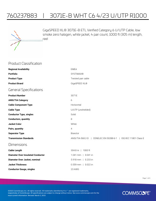
GigaSPEED XL® 3071E-B ETL Verified Category 6 U/UTP Cable, lowsmoke zero halogen, white jacket, 4 pair count, 1000 ft (305 m) length,reelProduct ClassificationRegional Availability EMEAPortfolio SYSTIMAX®Product Type Twisted pair cableProduct Brand GigaSPEED XL®General SpecificationsProduct Number3071EANSI/TIA Category6Cable Component Type HorizontalCable Type U/UTP (unshielded)Conductor Type, singles SolidConductors, quantity8Jacket Color WhitePairs, quantity4Separator Type BisectorTransmission Standards ANSI/TIA-568.2-D | CENELEC EN 50288-6-1 | ISO/IEC 11801 Class E DimensionsCable Length304.8 m | 1000 ftDiameter Over Insulated Conductor 1.041 mm | 0.041 inDiameter Over Jacket, nominal 5.918 mm | 0.233 inJacket Thickness0.559 mm | 0.022 inConductor Gauge, singles23 AWG13Page ofCross Section DrawingElectrical Specificationsdc Resistance Unbalance, maximum 5 %dc Resistance, maximum7.61 ohms/100 m | 2.32 ohms/100 ftDielectric Strength, minimum2500 VdcMutual Capacitance at Frequency 5.6 nF/100 m @ 1 kHzNominal Velocity of Propagation (NVP)70 %Operating Frequency, maximum300 MHzOperating Voltage, maximum80 VRemote Powering Fully complies with the recommendations set forth by IEEE 802.3bt (Type4) for the safe delivery of power over LAN cable when installed accordingto ISO/IEC 14763-2, CENELEC EN 50174-1, CENELEC EN 50174-2 or TIATSB-184-ASegregation Class cMaterial SpecificationsConductor Material Bare copperInsulation Material PolyolefinJacket Material Low Smoke Zero Halogen (LSZH)Separator Material PolyolefinPage of23Mechanical SpecificationsPulling Tension, maximum11.34 kg | 25 lbEnvironmental SpecificationsInstallation temperature0 °C to +60 °C (+32 °F to +140 °F)Operating Temperature-20 °C to +60 °C (-4 °F to +140 °F)Acid Gas Test Method EN 50267-2-3EN50575 CPR Cable EuroClass Fire Performance B2caEN50575 CPR Cable EuroClass Smoke Rating s1aEN50575 CPR Cable EuroClass Droplets Rating d0EN50575 CPR Cable EuroClass Acidity Rating a1Environmental Space Low Smoke Zero Halogen (LSZH)Smoke Test Method IEC 61034-2Packaging and WeightsCable weight38.097 kg/km | 25.6 lb/kftPackaging Type ReelRegulatory Compliance/CertificationsAgency ClassificationCENELEC EN 50575 compliant, Declaration of Performance (DoP) availableCHINA-ROHS Below maximum concentration valueISO 9001:2015Designed, manufactured and/or distributed under this quality management system REACH-SVHC Compliant as per SVHC revision on /ProductCompliance ROHSCompliantPage of33。
Motorola 3.5 kHz 产品说明书
RVN4126 3.59100-386-9100-386/T DEVICERVN41772-CD2-3.5MCS/MTSRVN41821-CD2-3.5XTS3000/SABER PORTABLE YES RKN4046KHVN9085 3.51-20 R NO HLN9359 PROG. STAND RVN4057 3.532 X 8 CODEPLUG NO3080385B23 & 5880385B30 MDVN4965 3.59100-WS/T CONFIG KITRVN4053 3.5ASTRO DIGITAL INTERFACE NO3080385B23RVN41842-CD RKN4046A (Portable) 2-3.5ASTRO PORTABLE /MOBILE YES3080369B73 or0180300B10 (Mobile) RVN41831-CD3080369B732-3.5ASTRO SPECTRA MOBILE YES(Low / Mid Power)0180300B10 (High Power) RVN4185CD ASTRO SPECTRA PLUS MOBILE NO MANY OPTIONS; SEESERVICE BRIEF#SB-MO-0101RVN4186CD ASTRO SPECTRA PLUS MANY OPTIONS;MOBILE/PORTABLE COMB SEE SERVICE BRIEF#SB-MO-0101RVN4154 3.5ASTROTAC 3000 COMPAR.3080385B23RVN5003 3.5ASTROTAC COMPARATORS NO3080399E31 Adpt.5880385B34RVN4083 3.5BSC II NO FKN5836ARVN4171 3.5C200RVN4029 3.5CENTRACOM SERIES II NO VARIOUS-SEE MANUAL6881121E49RVN4112 3.5COMMAND PLUS NORVN4149 3.5COMTEGRA YES3082056X02HVN6053CD CT250, 450, 450LS YES AAPMKN4004RVN4079 3.5DESKTRAC CONVENTIONAL YES3080070N01RVN4093 3.5DESKTRAC TRUNKED YES3080070N01RVN4091 3.5DGT 9000 DESKSET YES0180358A22RVN4114 3.5GLOBAL POSITIONING SYS.NO RKN4021AHVN8177 3.5GM/GR300/GR500/GR400M10/M120/130YES3080070N01RVN4159 3.5GP60 SERIES YES PMLN4074AHVN9128 3.5GP300 & GP350RVN4152 3.5GP350 AVSRVN4150 3.5GTX YES HKN9857 (Portable)3080070N01(Mobile) HVN9025CD HT CDM/MTX/EX SERIES YES AARKN4083/AARKN4081RiblessAARKN4075RIBLESS NON-USA RKN4074RVN4098H 3.5HT1000/JT1000-VISAR YES3080371E46(VISAR CONV)RVN4151 3.5HT1000 AVSRVN4098 3.5HT1000/ VISAR CONV’L.YES RKN4035B (HT1000) HVN9084 3.5i750YES HLN-9102ARVN4156 3.5LCS/LTS 2000YES HKN9857(Portable)3080070N01(Mobile) RVN4087 3.5LORAN C LOC. RECV’R.NO RKN4021ARVN4135 3.5M100/M200,M110,M400,R100 includesHVN9173,9177,9646,9774YES3080070N01RVN4023 3.5MARATRAC YES3080070N01RVN4019 3.5MAXTRAC CONVENTIONAL YES3080070N01RVN4139 3.5MAXTRAC LS YES3080070N01RVN4043 3.5MAXTRAC TRK DUPLEX YES3080070N01RVN4178CD MC SERIES, MC2000/2500DDN6124AW/DB25 CONNECTORDDN6367AW/DB9 CONNECTOR RVN41751-CD Rib to MIC connector 1-3.5MCS2000 RKN4062BRVN41131-3.5MCS2000RVN4011 3.5MCX1000YES3000056M01RVN4063 3.5MCX1000 MARINE YES3000056M01RVN4117 3.5MDC/RDLAP DEVICESRVN4105 3.5MOBILE PROG. TOOLRVN4119 3.5MOBITEX DEVICESRVN4128 3.5MPT1327-1200 SERIES YES SEE MANUALRVN4025 3.5MSF5000/PURC/ANALOG YES0180355A30RVN4077 3.5MSF5000/10000FLD YES0180355A30RVN4017K 3.5MT 1000YES RTK4205CRVN4148 3.5MTR 2000YES3082056X02RVN4140 3.5MTRI 2000NORVN41761-CD MTS2000, MT2000*, MTX8000, MTX90001-3.5*programmed by DOS which is included in the RVN4176RVN4131 3.5MTVA CODE PLUG FIXRVN4142 3.5MTVA DOCTOR YES3080070N01RVN4131 3.5MTVA3.EXERVN4013 3.5MTX800 & MTX800S YES RTK4205CRVN4097 1-CD MTX8000/MTX9000,MTS2000,MT2000*,* programmed by DOS which is included in the RVN4176HVN9067CD MTX850/MTX8250MTX950,MTX925RVN4138 3.5MTX-LS YES RKN4035DRVN4035 3.5MX 1000YES RTK4203CRVN4073 3.5MX 800YES RKN4006BHVN9395 P100, P200 LB, P50+, P210, P500, PR3000RVN4134 3.5P100 (HVN9175)P200 LB (HVN9794)P50+ (HVN9395)P210 (HVN9763)P500 (HVN9941)PR3000 (HVN9586)YES RTK4205HVN9852 3.5P110YES HKN9755A/REX1143 HVN9262 3.5P200 UHF/VHF YES RTK4205RVN4129 3.5PDT220YVN4051 3.5PORTABLE REPEATER Portable rptr.P1820/P1821AXRVN4061C 3.5PP 1000/500NO3080385B23 & 5880385B30 RVN5002 3.5QUANTAR/QUANTRO NO3O80369E31RVN4135 3.5R100 (HVN9177)M100/M200/M110/M400YES0180358A52RVN4146 3.5RPM500/660RVN4002 3.5SABER YES RTK4203CRVN4131 3.5SETTLET.EXEHVN9007 3.5SM50 & SM120YESRVN4039 3.5SMART STATUS YES FKN5825AHVN9054 3.5SOFTWARE R03.2 P1225YES3080070N01HVN9001 3.5SOFTWARE R05.00.00 1225LS YES HLN9359AHVN9012 3.5SP50RVN4001N 3.5SPECTRA YES3080369B73 (STANDARD)0180300B10 (HIGH POWER) RVN4099 3.5SPECTRA RAILROAD YES3080369B73RVN4110 3.5STATION ACCESS MODULE NO3080369E31RVN4089A 3.5STX TRANSIT YES0180357A54RVN4051 3.5SYSTEMS SABER YES RTK4203BRVN4075 3.5T5600/T5620 SERIES NO3080385B23HVN9060CD TC3000, TS3000, TR3000RVN4123 3.5VISAR PRIVACY PLUS YES3080371E46FVN4333 3.5VRM 100 TOOLBOX FKN4486A CABLE &ADAPTORRVN4133 3.5VRM 500/600/650/850NORVN4181CD XTS 2500/5000 PORTABLES RKN4105A/RKN4106A RVN41002- 3.5XTS3000 ASTRO PORTABLE/MOBILERVN4170 3.5XTS3500YES RKN4035DRIB SET UPRLN4008E RADIO INTERFACE BOX (RIB)0180357A57RIB AC POWER PACK 120V0180358A56RIB AC POWER PACK 220V3080369B71IBM TO RIB CABLE (25 PIN) (USE WITH XT & PS2)3080369B72IBM TO RIB CABLE (9 PIN)RLN443825 PIN (F) TO 9 PIN (M) ADAPTOR (USE W/3080369B72 FOR AT APPLICATION) 5880385B308 PIN MODULAR TO 25 PIN ”D” ADAPTOR (FOR T5600 ONLY)0180359A29DUPLEX ADAPTOR (MOSTAR/TRAXAR TRNK’D ONLY)Item Disk Radio RIB Cable Number Size Product Required Number Item Disk Radio RIB Cable Number Size Product Required NumberUtilizing your personal computer, Radio Service Software (RSS)/Customer Programming Software (CPS)/CustomerConfiguration Software (CCS) enables you to add or reprogram features/parameters as your requirements change. RSS/CPS/CCS is compatible with IBM XT, AT, PS/2 models 30, 50, 60 and 80.Requires 640K RAM. DOS 3.1 or later. Consult the RSS users guide for the computer configuration and DOS requirements. (ForHT1000, MT/MTS2000, MTX838/8000/9000, Visar and some newer products —IBM model 386, 4 MEG RAM and DOS 5.0 or higher are recommended.) A Radio Interface Box (RIB) may be required as well as the appropriate cables. The RIB and cables must be ordered separately.Licensing:A license is required before a software (RVN) order is placed. The software license is site specific (customer number and ultimate destination tag). All sites/locations must purchase their own software.Be sure to place subsequent orders using the original customer number and ship-to-tag or other licensed sites; ordering software without a licensed customer number and ultimate tag may result in unnecessary delays. To obtain a no charge license agreement kit, order RPX4719. To place an order in the U.S. call 1-800-422-4210. Outside the U.S., FAX 847-576-3023.Subscription Program:The purchase of Radio ServiceSoftware/Customer Programming/Customer ConfigurationSoftware (RVN & HVN kits) entitles the buyer/subscriber to three years of free upgrades. At the end of these three years, the sub-scriber must purchase the same Radio Service Software kit to receive an additional three years of free upgrades. If the sub-scriber does not elect to purchase the same Radio Service Software kit, no upgrades will be sent. Annually a subscription status report is mailed to inform subscribers of the RSS/CPS/CCS items on our database and their expiration dates.Notes:1)A subscription service is offered on “RVN”-Radio Service Software/Customer Programming/Customer Configuration Software kits only.2)“RVN” software must only be procured through Radio Products and Services Division (RPSD). Software not procured through the RPSD will not be recorded on the subscription database; upgrades will not be mailed.3)Upgrades are mailed to the original buyer (customer number & ultimate tag).4)SP software is available through the radio product groups.The Motorola General Radio Service Software Agreement is now available on Motorola Online. If you need assistance please feel free to submit a “Contact Us” or call 800-422-4210.SMART RIB SET UPRLN1015D SMART RIB0180302E27 AC POWER PACK 120V 2580373E86 AC POWER PACK 220V3080390B49SMARTRIB CABLE (9 PIN (F) TO 9 PIN (M) (USE WITH AT)3080390B48SMARTRIB CABLE (25 PIN (F) TO 9 PIN (M) (USE WITH XT)RLN4488ASMART RIB BATTERY PACKWIRELESS DATA GROUP PRODUTS SOFTWARERVN4126 3.59100-386/9100T DEVICES MDVN4965 3.59100-WS/T CONFIG’TN RVN41173.5MDC/RDLAP DEVICESPAGING PRODUCTS MANUALS6881011B54 3.5ADVISOR6881029B90 3.5ADVISOR ELITE 6881023B20 3.5ADVISOR GOLD 6881020B35 3.5ADVISOR PRO FLX 6881032B30 3.5BR8506881032B30 3.5LS3506881032B30 3.5LS5506881032B30 3.5LS7506881033B10 3.5LS9506881035B20 3.5MINITOR III8262947A15 3.5PAGEWRITER 20008262947A15 3.5PAGEWRITER 2000X 6881028B10 3.5TALKABOUT T3406881029B35 3.5TIMEPORT P7308262947A15 3.5TIMEPORT P930NLN3548BUNIVERSAL INTERFACE KITItem Disk Radio NumberSize Product。
- 1、下载文档前请自行甄别文档内容的完整性,平台不提供额外的编辑、内容补充、找答案等附加服务。
- 2、"仅部分预览"的文档,不可在线预览部分如存在完整性等问题,可反馈申请退款(可完整预览的文档不适用该条件!)。
- 3、如文档侵犯您的权益,请联系客服反馈,我们会尽快为您处理(人工客服工作时间:9:00-18:30)。
6
1 1 6
x1
ห้องสมุดไป่ตู้
Random variables
• If an RV can take arbitrary values in a real interval we say that the random variable is continuous • E.g. consider the sample space of weather temperature
– we know that it could be any number between -50 and 150 degrees Celsius – random variable T [-50,150] – note that the extremes do not have to be very precise, we can just say that P(T < -45o) = 0
Random variables
• A random variable X
– is a function that assigns a real value to each sample space outcome – we have already seen one such function: PX(x1,x2) = 1/36 for all outcome-pairs (x1,x2) (viewing an outcome as an atomic event)
– Collectively Exhaustive: all possible x2 distinguishable outcomes are listed 6 separately in the universal set U and when an experiment is performed one of these outcomes must occur. – Mutually Exclusive: if one outcomes happens then no other can occur (if x1 = 5 it cannot be 1 anything else).
• Notation:
– Specify both the random variable, X, and the value, x, that it takes in your probability statements. E.g., X(u) = x for any outcome u in U. – Another example: In a probability measure, specify the random variable as a subscript, PX (x) ,and the value x as the argument. For example
PX (x) = PX (x1,x2) = 1/36
means Prob[X = (x1,x2)] = 1/36 – Without such care, probability statements can be hopelessly confusing
Random variables
• Two types of random variables:
1
6
x1
Probability measure
• Probability of an event:
– A number expressing the chance that the event will occur when a random experiment is performed.
• A probability measure satisfies the Three Kolmogorov Axioms:
2
• e.g.
– P(x1 0) = 1 – P(x1 even U x1 odd) = P(x1 even)+ P(x1 odd)
6
1 1 6
x1
Probability measure
• The last axiom of the three, when combined with the mutually exclusive property of the sample set,
– Suppose that the probability of the elementary event consisting of any single outcome-pair, x2 A = {(x1,x2)}, is P(A) = 1/36 6 – We can then compute the probabilities of all events, including compound events:
P(x2 odd) = 18x1/36 = 1 P(U) = 36x1/36 = 1 P(two sixes) = 1/36 P(x1 = 2 and x2 = 6) = 1/36
1 1 6
x1
Probability measure
• Note that there are many ways to decompose the universal event U (the “ultimate” compound event) into the disjoint union of simpler events: x2
– If there are furthermore only a finite set of possibilities, the discrete RV is finite. For example, in the two-throws-of-a-die example, there are only (at most) 36 possible values that an RV can take:
two sixes x1 = 2 and x2 = 6
x2
6
• Example of a random event:
– An odd number occurs on the 2nd toss.
1 1 6
x1
Sample space
• The sample space, U, is a set of experimental outcomes that must satisfy the following two properties:
– allows us to easily assign probabilities to all possible events if the probabilities of atomic events, aka elementary events, are known
• Back to our dice example:
• The mutually exclusive property of outcomes simplifies the calculation of the probability of events • Collectively exhaustive means that there is no possible event to which we cannot assign a probability • The universe (= sample space) of possible experimental outcomes, U, is equal to the event, “something happens” when an experiment is performed. Thus we also call U the Universal Event
Review of probability
Ken Kreutz-Delgado Nuno Vasconcelos
ECE Department, UCSD ECE 175A - Winter 2011
Probability
• probability is the language to deal with processes or experiments that are non-deterministic
• examples:
– if I flip a coin 100 times, how many can I expect to see heads? – what is the weather going to be like tomorrow? – are my stocks going to be up or down?
– this can be thought of as a normalized histogram – satisfies the following properties
• Most probability notions apply equal well to discrete and continuous random variables
Discrete RV
• for a discrete RV the probability assignments given by a probability mass function (PMF)
– The outcomes of the random experiment are used to define random Events
Events are sets of outcomes
• Example of a random experiment:
– Roll a die twice consecutively – call the value on the up face at the nth toss xn for n = 1,2 – Possible process outcomes