NLC565050T-220K-S中文资料
S4610

Benefitsl Improved Gate, Avalanche and Dynamic dV/dt Ruggednessl Fully Characterized Capacitance and Avalanche SOAl Enhanced body diode dV/dt and dI/dt CapabilityPD - 96906BD 2Pak IRFS4610TO-220AB IRFB4610TO-262IRFSL4610IRFB4610IRFS4610IRFSL4610HEXFET ® Power MOSFETApplicationsl High Efficiency Synchronous Rectification in SMPS l Uninterruptible Power Supply l High Speed Power SwitchinglHard Switched and High Frequency Circuits SD G SD G SD GIRF/B/S/SL4610Notes:Repetitive rating; pulse width limited by max. junction temperature.Limited by T Jmax , starting T J = 25°C, L = 0.39mHR G = 25Ω, I AS = 44A, V GS =10V. Part not recommended for use above this value.I SD ≤ 44A, di/dt ≤ 660A/µs, V DD ≤ V (BR)DSS , T J ≤ 175°C. Pulse width ≤ 400µs; duty cycle ≤ 2%.C oss eff. (TR) is a fixed capacitance that gives the same charging timeas C oss while V DS is rising from 0 to 80% V DSS .C oss eff. (ER) is a fixed capacitance that gives the same energy as C oss while V DS is rising from 0 to 80% V DSS .When mounted on 1" square PCB (FR-4 or G-10 Material). For recommended footprint and soldering techniques refer to application note #AN-994. R θ is measured at T J approximately 90°CIRF/B/S/SL4610Fig 3. Typical Transfer CharacteristicsFig 4. Normalized On-Resistance vs. TemperatureFig 6. Typical Gate Charge vs. Gate-to-Source VoltageFig 5. Typical Capacitance vs. Drain-to-Source Voltage 110100V DS , Drain-to-Source Voltage (V)100020003000400050006000C , C a p a c i t a n c e (p F )20406080100120140Q G Total Gate Charge (nC)048121620V G S , G a t e -t o -S o u r c e V o l t a g e (V )IRF/B/S/SL4610Fig 8. Maximum Safe Operating AreaFig 10. Drain-to-Source Breakdown VoltageFig 11. Typical C OSS Stored EnergyFig 9. Maximum Drain Current vs.Case TemperatureFig 12. Maximum Avalanche Energy Vs. DrainCurrent0.11.010.0100.01000.0I S D , R e v e r s e D r a i n C u r r e n t (A )255075100125150175T J , Junction Temperature (°C)020406080I D , D r a i n C u r r e n t (A )T J , Junction Temperature (°C)V, D r a i n -t o -S o u r c e B r e a k d o w n V o l t a g e20406080100V DS, Drain-to-Source Voltage (V)0.00.51.01.52.0E n e r g y (µJ)255075100125150175Starting T J , Junction Temperature (°C)040080012001600E A S , S i n g l e P u l s e A v a l a n c h e E n e r g y (m J )1101001000V DS , Drain-toSource Voltage (V)0.11101001000I D , D r a i n -t o -S o u r c e C u r r e n t (A)IRF/B/S/SL4610t1 , Rectangular Pulse Duration (sec)Fig 13. Maximum Effective Transient Thermal Impedance, Junction-to-CaseFig 14. Typical Avalanche Current vs.PulsewidthFig 15. Maximum Avalanche Energy vs. TemperatureNotes on Repetitive Avalanche Curves , Figures 14, 15:(For further info, see AN-1005 at )1.Avalanche failures assumption:Purely a thermal phenomenon and failure occurs at a temperature far inexcess of T jmax. This is validated for every part type.2. Safe operation in Avalanche is allowed as long asT jmax is not exceeded.3. Equation below based on circuit and waveforms shown in Figures 16a, 16b.4. P D (ave) = Average power dissipation per single avalanche pulse.5. BV = Rated breakdown voltage (1.3 factor accounts for voltage increaseduring avalanche).6. I av = Allowable avalanche current.7. ∆T = Allowable rise in junction temperature, not to exceed T jmax (assumed as25°C in Figure 14, 15).t av = Average time in avalanche.D = Duty cycle in avalanche = t av ·fZ thJC(D, t av) = Transient thermal resistance, see Figures 13)P D (ave) = 1/2 ( 1.3·BV·I av) =D T/ Z thJCI av =2D T/ [1.3·BV·Z th]E AS (AR) = P D (ave)·t avtav (sec)AvalancheCurrent(A)255075100125150175Starting T J , Junction Temperature (°C)100200300400EAR,AvalancheEnergy(mJ)IRF/B/S/SL4610Fig. 17 - Typical Recovery Current vs. di f /dtFig 16. Threshold Voltage Vs. TemperatureFig. 19 - Typical Stored Charge vs. di f /dtFig. 18 - Typical Recovery Current vs. di f /dtT J , Temperature ( °C )V G S (t h ) G a t e t h r e s h o l d V o l t a g e (V )di f / dt - (A / µs)I R R M - (A )di f / dt - (A / µs)I R R M - (A )di f / dt - (A / µs)Q R R - (n C )di f / dt - (A / µs)Q R R - (n C )IRF/B/S/SL4610Fig 23a. Switching Time Test Circuit Fig 23b.Switching Time WaveformsV V DS90%d(on)d(off)rfFig 22b. Unclamped Inductive WaveformsFig 22a.Unclamped Inductive Test CircuitI ASV DDIdQgs1Qgs2Qgd QgodrFig 21. Peak Diode Recovery dv/dt Test Circuit for N-Channel® Power MOSFETs* V GS = 5V for Logic Level DevicesIRF/B/S/SL4610TO-220AB Package Outline Dimensions are shown in millimeters (inches)TO-262 Package OutlineIRF/B/S/SL4610 11Data and specifications subject to change without notice.This product has been designed and qualified for the Automotive [Q101] market.Qualification Standards can be found on IR’s Web site.IR WORLD HEADQUARTERS: 233 Kansas St., El Segundo, California 90245, USA Tel: (310) 252-7105TAC Fax: (310) 252-7903Visit us at for sales contact information . 11/04D 2Pak Tape & Reel Information344TRRFEED DIRECTION1.85 (.073)1.65 (.065)1.60 (.063)1.50 (.059)4.10 (.161)3.90 (.153)TRLFEED DIRECTION 10.90 (.429)10.70 (.421)16.10 (.634)15.90 (.626)1.75 (.069)1.25 (.049)11.60 (.457)11.40 (.449)15.42 (.609)15.22 (.601)4.72 (.136)4.52 (.178)24.30 (.957)23.90 (.941)0.368 (.0145)0.342 (.0135)1.60 (.063)1.50 (.059)13.50 (.532)12.80 (.504)330.00(14.173) MAX.27.40 (1.079)23.90 (.941)60.00 (2.362) MIN.30.40 (1.197) MAX.26.40 (1.039)24.40 (.961)NOTES :1. COMFORMS TO EIA-418.2. CONTROLLING DIMENSION: MILLIMETER.3. DIMENSION MEASURED @ HUB.4. INCLUDES FLANGE DISTORTION @ OUTER EDGE.。
DCRS-5650-28(C)T&52(C)T交换机安装手册

DCRS-5650-28CT、DCRS-5650-52CT、DCRS-5650-28C 以及 DCRS-5650-52C 支 持 SNMP,支持带内和带外管理,支持命令行方式与 web 方式对交换机进行管理,支持 RMON。可采用神州数码集中网管系统 LinkManager 统一管理,方便简捷。
DCRS-5650-28CT 路由交换机的前面板如下图所示:
图 1-5 DCRS-5650-28CT 前面板
DCRS-5650-52CT 路 由 交 换 机 的 前 面 板 上 有 48 个 10/100 自 适 应 电 口 , 两 个 10/100/1000 自适应电口,2 个千兆 combo 口(SFP 光口或 10/100/1000 自适应电口),1 个 Console 端口和 55 个 LED 指示灯。
第 2 章 设备安装 .........................................................................2-1
2.1 安装须知..........................................................................2-1
1.4 产品外观..........................................................................1-3
1.4.1 产品前面板 ............................................................................................. 1-3 1.4.2 产品后面板 ............................................................................................. 1-4 1.4.3 LED指示灯说明....................................................................................... 1-5
常用三极管参数大全
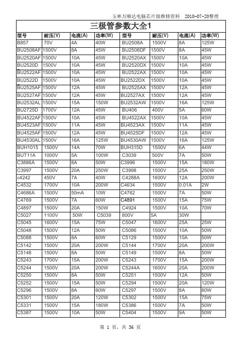
玉林万顺达电脑芯片级维修资料 2010-07-20整理玉林万顺达电脑芯片级维修资料 2010-07-20整理玉林万顺达电脑芯片级维修资料 2010-07-20整理玉林万顺达电脑芯片级维修资料 2010-07-20整理玉林万顺达电脑芯片级维修资料 2010-07-20整理玉林万顺达电脑芯片级维修资料 2010-07-20整理玉林万顺达电脑芯片级维修资料 2010-07-20整理玉林万顺达电脑芯片级维修资料 2010-07-20整理玉林万顺达电脑芯片级维修资料 2010-07-20整理玉林万顺达电脑芯片级维修资料 2010-07-20整理玉林万顺达电脑芯片级维修资料 2010-07-20整理玉林万顺达电脑芯片级维修资料 2010-07-20整理玉林万顺达电脑芯片级维修资料 2010-07-20整理玉林万顺达电脑芯片级维修资料 2010-07-20整理玉林万顺达电脑芯片级维修资料 2010-07-20整理玉林万顺达电脑芯片级维修资料 2010-07-20整理玉林万顺达电脑芯片级维修资料 2010-07-20整理玉林万顺达电脑芯片级维修资料 2010-07-20整理玉林万顺达电脑芯片级维修资料 2010-07-20整理玉林万顺达电脑芯片级维修资料 2010-07-20整理玉林万顺达电脑芯片级维修资料 2010-07-20整理玉林万顺达电脑芯片级维修资料 2010-07-20整理玉林万顺达电脑芯片级维修资料 2010-07-20整理玉林万顺达电脑芯片级维修资料 2010-07-20整理玉林万顺达电脑芯片级维修资料 2010-07-20整理玉林万顺达电脑芯片级维修资料 2010-07-20整理玉林万顺达电脑芯片级维修资料 2010-07-20整理玉林万顺达电脑芯片级维修资料 2010-07-20整理玉林万顺达电脑芯片级维修资料 2010-07-20整理玉林万顺达电脑芯片级维修资料 2010-07-20整理。
5N60 产品资料 5N60 产品资料

Qrr
/dt=100A/us
2.2
uC
注释:
⑴ 重复范围: 脉冲宽度受结温限制
⑵ L = 18.9mH, IAS = 4.5A, VDD = 50V, RG = 25 Ω, 开始TJ = 25°C ⑶ ISD ≤ 4.5A, di/dt ≤200A/μs, VDD ≤ BVDSS, 开始 TJ = 25°C
6-3
5N60 产品资料
源-漏二极管特性
参数名称
符号
测试条件
单 规范值
位
最小 典型
最大
二极管正向电压 VSD
VGS =0V;IS=4.5A
1.4
V
持续源电流
IS MOSEFT 内部反向 P-N 结二
4.5
A
脉冲源电流
ISM
极管
18
A
反向恢复时间
trr
VGS =0V;IS=4A; dIF
300
ns
反向恢复电荷
⑷ 脉冲测试: 脉冲宽度<= 300us, 占空比<=2%
(5)工作温度必须单独
3. 测试电路及波形
Fig. 1A 峰值二极管恢复 dv/dt 测试电路
地址(ADD):无锡新区硕放香楠一路 9 号 网址(Http):
电话(Tel):0510-80259777 传真(Fax):0510-82261222
BVDSS IDSS IGSS
VGS(th) RDS(on)
GFS
CiSS COSS CrSS
Td(on) tr
Td(off) tf Qg
VGS =0V;ID=250uA VDS =600V;VGS =0V VDS =30V;VGS =0V VDS =-30V;VGS =0V
lg lw650 投影仪用户手册 - 技术指南说明书

LX750/LW650/LS+700/LW720U s e r M a n u a l-Te c h n i c a l G u i d e020-000161-02ProjectorLW650/LS+700/LX750/LW720 User's Manual – Operating GuideThe following signals are used for the initial settings. The signal timing of some computer models may be different. In such case, adjust the items V POSITION and H POSITION in the IMAGE menu.Back porch (B) Front porch (D) Back porch (b) Front porch (d) Display time (C)Display time (c)Data DataH. Sync. V. Sync.Sync (A) Sync (a)Computer/ Signal Horizontal signal timing (μs)Computer/SignalVertical signal timing (lines) (A)(B)(C)(D)(a)(b)(c)(d)TEXT 2.0 3.020.3 1.0TEXT3424001 VGA (60Hz) 3.8 1.925.40.6VGA (60Hz)23348010 VGA (72Hz) 1.3 4.120.30.8VGA (72Hz)3284809 VGA (75Hz) 2.0 3.820.30.5VGA (75Hz)3164801 VGA (85Hz) 1.6 2.217.8 1.6VGA (85Hz)3254801 SVGA (56Hz) 2.0 3.622.20.7SVGA (56Hz)2226001 SVGA (60Hz) 3.2 2.220.0 1.0SVGA (60Hz)4236001 SVGA (72Hz) 2.4 1.316.0 1.1SVGA (72Hz)62360037 SVGA (75Hz) 1.6 3.216.20.3SVGA (75Hz)3216001 SVGA (85Hz) 1.1 2.714.20.6SVGA (85Hz)3276001 Mac 16" mode 1.1 3.914.50.6Mac 16" mode3396241 XGA (60Hz) 2.1 2.515.80.4XGA (60Hz)6297683 XGA (70Hz) 1.8 1.913.70.3XGA (70Hz)6297683 XGA (75Hz) 1.2 2.213.00.2XGA (75Hz)3287681 XGA (85Hz) 1.0 2.210.80.5XGA (85Hz)33676811152 x 864(75Hz) 1.2 2.410.70.61152 x 864(75Hz)33286411280 x 960(60Hz) 1.0 2.911.90.91280 x 960(60Hz)3369601SXGA (60Hz) 1.0 2.311.90.4SXGA(60Hz)33810241 SXGA (75Hz) 1.1 1.89.50.1SXGA (75Hz)33810241 SXGA (85Hz) 1.0 1.48.10.4SXGA (85Hz)34410241 UXGA (60Hz) 1.2 1.99.90.4UXGA (60Hz)34612001 W-XGA (60Hz) 1.7 2.516.00.8W-XGA (60Hz)3237681 SXGA+ (60Hz) 1.2 1.911.50.7SXGA+ (60Hz)432105031280 x800(60Hz) 1.6 2.415.30.81280 x800(60Hz)3248001A COMPUTER IN1,B COMPUTER IN2,C MONITOR OUT D-sub 15pin mini shrink jack• Video signal: RGB separate, Analog, 0.7Vp-p, 75Ω terminated (positive)• H/V. sync. signal: TTL level (positive/negative)• Composite sync. signal: TTL levelAt RGB signalPin SignalPin Signal1Video Red 9(No connection)2Video Green 10Ground3Video Blue11(No connection)4(No connection)12A ,B : SDA (DDC data), C : (No connection)5Ground13H. sync / Composite sync.6Ground Red 14V. sync.7Ground Green 15A ,B : SCL (DDC clock), C : (No connection)8Ground BlueD BNC (G/Y, B/Cb/Pb, R/Cr/Pr, H, V)• BNC jack x 5• Video : Analog 0.7Vp-p, 75Ω terminator • H/V, sync, : TTL level (positive/negative)• Composite sync, : TTL levelCOMPONENT VIDEO E Y, F Cb/Pb, G Cr/PrRCA jack x3• System: 480i@60, 480p@60, 576i@50, 576p@50, 720p@50/60, 1080i@50/60, 1080p@50/60Port Signal Y Component video Y , 1.0±0.1Vp-p, 75Ω terminator with composite sync Cb/Pb Component video Cb/Pb, 0.7±0.1Vp-p, 75Ω terminator Cr/Pr Component video Cr/Pr, 0.7±0.1Vp-p, 75Ω terminatorREMOTE CONTROL K IN L OUTØ3.5 stereo mini jack• To be connected with the remote control that came with the projector.CONTROL M IN N OUTD-sub 9pin plug• About the details of RS-232C communication, please refer to the following RS-232C Communication in this manual.Pin Signal Pin Signal Pin Signal 1(No connection)4(No connection)7RTS 2RD 5Ground8CTS3TD6(No connection)9(No connection)I VIDEO 1RCA jack• System: NTSC, PAL, SECAM, PAL-M, PAL-N, NTSC4.43• 1.0±0.1Vp-p, 75Ω terminator H S-VIDEO Mini DIN 4pin jack Pin Signal1Color signal 0.286Vp-p (NTSC, burst), 75Ω terminatorColor signal 0.300Vp-p (PAL/SECAM, burst) 75Ω terminator 2Brightness signal, 1.0Vp-p, 75Ω terminator 3Ground 4GroundJ VIDEO 2BNC jack• System: NTSC, PAL, SECAM, PAL-M, PAL-N, NTSC4.43• 1.0±0.1Vp-p, 75Ω terminatorO HDMI• Type :Digital video connector PinSignalPinSignalPinSignal1T.M.D.S. Data2 +8T.M.D.S. Data0 Shield 15SCL 2T.M.D.S. Data2 Shield 9T.M.D.S. Data0 -16SDA3T.M.D.S. Data2 -10T.M.D.S. Clock +17DDC/CEC Ground 4T.M.D.S. Data1 +11T.M.D.S. Clock Shield 18+5V Power5T.M.D.S. Data1 Shield 12T.M.D.S. Clock -19Hot Plug Detect6T.M.D.S. Data1 -13CEC7T.M.D.S. Data0 +14Reserved(N.C. on device)P DVI-DDVI-D jack (digital to digital)PinSignalPinSignalPinSignal1T.M.D.S. Data2 -9T.M.D.S. Data1 -17T.M.D.S. Data0 -2T.M.D.S. Data2 +10T.M.D.S. Data1 +18T.M.D.S. Data0 +3T.M.D.S. Data2/4 Shield 11T.M.D.S. Data1/3 Shield 19T.M.D.S. Data0/5 Shield 4-12-20-5-13-21-6DDC Clock 14+5V Power22T.M.D.S. Clock Shield 7DDC Data 15Ground (for +5V)23T.M.D.S. Clock +8-16Hot Plug Detect24T.M.D.S. Clock -Q LANRJ-45 jack Pin Signal Pin Signal Pin Signal1TX+4-7-2TX-5-8-3RX+6RX-Commands Control Description Parameter or ResponsePOWR Power Contorol 0 = Standby1 = Power OnPOWR ?Power Status inquiry 0 = Standby1 = Power On2 = Cool DownINPT Input Source selection 11 = COMPUTER IN 112 = COMPUTER IN 213 = BNC21 = COMPONENT22 = S-VIDEO23 = VIDEO 124 = VIDEO 231 = HDMI32 = DVI-DINPT ?Input Source inquiry 11 = COMPUTER IN 112 = COMPUTER IN 213 = BNC21 = COMPONENT22 = S-VIDEO23 = VIDEO 124 = VIDEO 231 = HDMI32 = DVI-DAVMT AV Mute 30 = BLANK off31 = BLANK onAVMT ?AV Mute inquiry 30 = BLANK off31 = BLANK onERST ?Error Status inquiry 1st byte: Refers to Fan error; one of 0 to 22nd byte: Refers to Lamp error; one of 0 to 23rd byte: Refers to Temptrature error; one of 0 to 2 4th byte: Refers to Cover error; one of 0 to 25th byte: Refers to Filter error; one of 0 to 26th byte: Refers to Other error; one of 0 to 2The mearning of 0 to 2 is as given below0 = Error is not detected; 1 = Warning; 2 = ErrorThis projector is equipped with the PJLink TM Class 1.See the following table for the commands for controlling the projector using the PJLink TM protocol are as given in the table below.Commands Control Description Parameter or ResponseLAMP ?Lamp Status inquiry 1st number (digits 1 to 5): Lamp Time2nd number : 0 = Lamp off, 1 = Lamp onINST ?Input Source List inquiry11 12 13 21 22 23 24 31 32NAME ?Projector Name inquiry Responds with the name set in "PROJECTOR NAME" of "NETWORK"INF1 ?Manufacturer's Name inquiry CHRISTIEINF2 ?Model Name inquiry LX750 (XGA model)LW650/LW720 (WXGA model) LS+700 (SXGA+ model)INFO ?Other Information inquiry Responds with the factory information and so on CLSS ?Class Information inquiry1NOTE • The password used in PJLink TM is the same as the password set in the Web Brouwser Comtrol. To use PJLink TM without authentication, do not set any password in Web Browser Control.• For specifications of PJLink TM, see the web site of the Japan BusinessMachine and Information System Industries Association.URL: http://pjlink.jbmia.or.jp/CONTROL port RS-232C cable (Cross) RS-232C port of the projector of the computer- (1) (1) CDRD (2) (2) RDTD (3) (3) TD- (4) (4) DTRGND (5) (5) GND- (6) (6) DSRRTS (7) (7) RTSCTS (8) (8) DTS- (9) (9) RIConnecting the cable1. Turn off the projector and the computer.2. Connect the CONTROL port of the projector with a RS-232C port ofthe computer by a RS-232C cable (cross). Use the cable that fulfills the specification shown in the previous page.3. Turn the computer on, and after the computer has started up turn theprojector on.Communications setting19200bps, 8N11. ProtocolConsist of header (7 bytes) + command data (6 bytes).2. HeaderBE + EF + 03 + 06 + 00 + CRC_low + CRC_highCRC_low : Lower byte of CRC flag for command dataCRC_high : Upper byte of CRC flag for command data3. Command dataCommand data chartbyte_0byte_1byte_2byte_3byte_4byte_5Action Type Setting codelow high low high low highAction (byte_0 - 1)Action Classification Content1SET Change setting to desired value.2GET Read projector internal setup value.4INCREMENT Increment setup value by 1.5DECREMENT Decrement setup value by 1.6EXECUTE Run a command.Requesting projector status (Get command)(1) Send the request code Header + Command data (‘02H’+‘00H’+ type (2bytes)+‘00H’ +‘00H’) from the computer to the projector.(2) The projector returns the response code ‘1DH’+ data (2 bytes) to the computer. Changing the projector settings (Set command)(1) Send the setting code Header + Command data (‘01H’+‘00H’+ type (2 bytes) +setting code (2 bytes)) from the computer to the projector.(2) The projector changes the setting based on the above setting code.(3) The projector returns the response code ‘06H’ to the computer.Using the projector default settings (Reset Command)(1) The computer sends the default setting code Header + Command data(‘06H’+‘00H’ + type (2 bytes) +‘00H’+‘00H’) to the projector.(2) The projector changes the specified setting to the default value.(3) The projector returns the response code ‘06H’ to the computer.Increasing the projector setting value (Increment command)(1) The computer sends the increment code Header + Command data(‘04H’+‘00H’+ type (2 bytes) +‘00H’+‘00H’) to the projector.(2) The projector in creases the setting value on the above setting code.(3) The projector returns the response code ‘06H’ to the computer.Decreasing the projector setting value (Decrement command)(1) The computer sends the decrement code Header + Command data(‘05H’+‘00H’+ type (2 bytes) +‘00H’ + ‘00H’) to the projector.(2) The projector decreases the setting value on the above setting code.(3) The projector returns the response code ‘06H’ to the computer.When the projector cannot understand the received commandWhen the projector cannot understand the received command, the error code ‘15H’ is sent back to the computer.Sometimes the projector cannot properly receive the command. In such a case, the command is not executed and the error code ‘15H’ is sent back to the computer. If this error code is returned, send the same command again.When the projector cannot execute the received command.When the projector cannot execute the received command, the error code ‘1CH’ + ‘xxxxH’ is sent back to the computer. When the data length is greater than indicated by the data length code, the projector ignore the excess data code. Conversely when the data length is shorter than indicated by the data length code, an error code will be returned to the computer.NOTE • Operation cannot be guaranteed when the projector receives an undefined command or data.• Provide an interval of at least 40ms between the response code and any other code.• The projector outputs test data when the power supply is switched ON, and when the lamp is lit. Ignore this data.• Commands are not accepted during warm-up.Communication PortThe following two ports are assigned for the command control.TCP #23TCP #9715Command Control SettingsConfigure the following items form a web browser when command control is used. Port SettingsNetwork Control Port1 (Port: 23)Port openClick the [Enable] check box to open [NetworkControl Port1 (Port: 23)] to use TCP #23.Default setting is “Enable”.AuthenticationClick the [Enable] check box for the[Authentication] setting when authenticationis required.Default setting is “Disable”.Network Control Port2 (Port: 9715)Port openClick the [Enable] check box to open [NetworkControl Port2 (Port: 9715)] to use TCP#9715.Default setting is “Enable”.AuthenticationClick the [Enable] check box for the[Authentication] setting when authenticationis required.Default setting is “Enable”.Security SettingsNetwork Control AuthenticationPasswordEnter the desired authentication password.This setting will be the same for [NetworkControl Port1 (Port: 23)] and [NetworkControl Port2 (Port: 9715)].Default setting is blank.Re-enterAuthenticationPasswordWhen the authentication setting is enabled, the following settings are required.Command Format[TCP #23]1. ProtocolConsist of header (7 bytes) + command data (6 bytes)2. HeaderBE + EF + 03 + 06 + 00 + CRC_low + CRC_highCRC_low: Lower byte of CRC flag for command dataCRC_high: Upper byte of CRC flag for command data3. Command dataCommand data chartbyte_0byte_1byte_2byte_3byte_4byte_5Action Type Setting codelow high low high low highAction (byte_0 - 1)Action Classification Content1Set Change setting to desired value.2Get Read projector internal setup value.4Increment Increment setup value by 1.5Decrement Decrement setup value by 1.6Execute Run a command.Requesting projector status (Get command)(1) Send the following request code from the PC to the projector.Header + Command data (‘02H’ + ‘00H’ + type (2 bytes) + ‘00H’ + ‘00H’) (2) The projector returns the response code ‘1DH’ + data (2 bytes) to the PC. Changing the projector settings (Set command)(1) Send the following setting code from the PC to the projector.H eader + Command data (‘01H’ + ‘00H’ + type (2 bytes) + setting code (2 bytes))(2) The projector changes the setting based on the above setting code.(3) The projector returns the response code ‘06H’ to the PC.Using the projector default settings (Reset Command)(1) The PC sends the following default setting code to the projector.Header + Command data (‘06H’ + ‘00H’ + type (2 bytes) + ‘00H’ + ‘00H’)(2) The projector changes the specified setting to the default value.(3) The projector returns the response code ‘06H’ to the PC.Increasing the projector setting value (Increment command)(1) The PC sends the following increment code to the projector.Header + Command data (‘04H’ + ‘00H’ + type (2 bytes) + ‘00H’ + ‘00H’)(2) The projector increases the setting value on the above setting code.(3) The projector returns the response code ‘06H’ to the PC.Decreasing the projector setting value (Decrement command)(1) The PC sends the following decrement code to the projector.Header + Command data (‘05H’ + ‘00H’ + type (2 bytes) + ‘00H’ + ‘00H’)(2) The projector decreases the setting value on the above setting code.(3) The projector returns the response code ‘06H’ to the PC.When the projector cannot understand the received commandWhen the projector cannot understand the received command, the error code ‘15H’ is sent back to the PC.Sometimes the projector cannot properly receive the command. In such a case, the command is not executed and the error code ‘15H’ is sent back to the PC. If this error code is returned, send the same command again.When the projector cannot execute the received command.When the projector cannot execute the received command, the error code ‘1CH’ + ‘xxxxH’ is sent back to the PC.When the data length is greater than indicated by the data length code, the projector ignore the excess data code. Conversely when the data length is shorter than indicated by the data length code, an error code will be returned to the PC.When authentication error occurred.When authentication error occurred, the error code the ‘1FH’ + ‘0400H’ is sent back to the PC.[TCP #9715]1. ProtocolConsist of header (1 byte) + data length (1 byte) + command data (13 bytes) + check sum (1 bytes) + connection ID (1 byte).2. Header 02, Fixed3. Data LengthNetwork control commands byte length (0D, Fixed)4. Command dataNetwork control commands that start with BE EF (13bytes).5. Check SumThis is the value to make zero on the addition of the lower 8 bits from the header to the checksum.6. Connection IDRandom value from 0 to 255 (This value is attached to the reply data).NOTE • Operation cannot be guaranteed when the projector receives an undefined command or data.• Provide an interval of at least 40ms between the response code and any other code.• Commands are not accepted during warm-up.7. Reply DataThe connection ID (the data is same as the connection ID data on the sending data format) is attached to the Network control commands reply data.ACK reply: ‘06H’ + ‘xxH’NAK reply: ‘15H’ + ‘xxH’Error reply: ‘1CH’ + ‘xxxxH’ + ‘xxH’Data reply: ‘1DH’ + ‘xxxxH’ + ‘xxH’Projector busy reply: ‘1FH’ + ‘xxxxH’ + ‘xxH’Authentication error reply: ‘1FH’ + ‘0400H’ + ‘xxH’(‘xxH’ : connection ID)Automatic Connection BreakThe TCP connection will be automatically disconnected after there is no communication for 30 seconds after being established.AuthenticationThe projector does not accept commands without authentication success when authentication is enabled. The projector uses a challenge response type authentication with an MD5 (Message Digest 5) algorithm. When the projector is using a LAN, a random 8 bytes will be returned if authentication is enabled. Bind this received 8 bytes and the authentication password and digest this data with the MD5 algorithm and add this in front of the commands to send.Following is a sample if the authentication password is set to “password” and the random 8 bytes are “a572f60c”.1) Select the projector.2) Receive the random 8 bytes “a572f60c” from the projector.3) B ind the random 8 bytes “a572f60c” and the authentication password“password” and it becomes “a572f60cpassword”.4) D igest this bind “a572f60cpassword” with MD5 algorithm.It will be “e3d97429adffa11bce1f7275813d4bde”.5) A dd this “e3d97429adffa11bce1f7275813d4bde” in front of the commands andsend the data.Send “e3d97429adffa11bce1f7275813d4bde”+command.6) W hen the sending data is correct, the command will be performed and thereply data will be returned. Otherwise, an authentication error will be returned.NOTE• As for the transmission of the second or subsequent commands, the authentication data can be omitted when the same connection.munications settingSet the same communication settings (selecting from options below) on theCONTROL terminal for transmitting and receiving side connected with a RS-232C cable.Baud rate: 4800 / 9600 / 19200 / 38400 bps Parity NONE / ODD / EVEN Data bit: 8 bit (fixed)Start bit: 1 bit (fixed)Stop bit: 1 bit (fixed)mans available only for daisy chain communicationThe projector supports the following commands only for daisy chain.(1) Control the projector (Set/Increment/Decrement/Execute)(2) Get the projector’s status (Get)(3) Get the number of connected projectors(4) Set the communication Group identification and Communication ID.(5) Get the communication Group identification and Communication ID.mand formatProtocolConsist of header data (7 bytes) + command data (6 bytes)HeaderBE + EF + Packet_Type + 06 + Group + ID + Checksum Data chartSupport Command Packet_TypeGroup ID Control the projector‘83H’0~160~64Get the projector’s status‘83H’1~161~64Get the number of connected projectors ‘84H’00Set the communication Groupidentification and Communication ID ‘85H’1~161~64Get the communication Groupidentification and Communication ID‘86H’CONTROL OUT port in Projector CONTROL IN port in ProjectorRS-232C cable (Cross)- (1) (1) CD RD (2) (2) RD TD (3) (3) TD - (4) (4) DTR GND (5)(5) GND - (6) (6) DSR RTS (7) (7) RTS CTS (8)(8) DTS- (9)(9) RICalculation of ChecksumSum up all of 12 bytes except the Checksum, then make the bit inversion of the lowest byte of the total, and add 1 to the inverted byte. The calculated result is the Checksum data.Exp. Communication Group: A / Communication ID: 1Header data (7 bytes)Command data (6 bytes)Header PacketType Data Size Group ID Checksum Action Type SettingCodeBE EF830601016601 0000 6001 00 BE + EF + 83 + 06 + 01 + 01 + 01 + 00 + 00 + 60 + 01 + 00 = ‘029AH’The lowest byte of ‘029AH’ is ‘9AH’ (1001 1010). Making the bit inversion of the ‘9AH’ gets ‘65H’ (0110 0101), then, add 1. The calculated checksum is ’66H’. Group and ID SettingsThis daisy chain command can adjust the control range by using the Group identification and ID.Group ID Direction note1~161~64Individual control The command is available to the projectors havingthe same Group identification and ID numbers withcommand setting.1~160Designated controlaccording to theGroup identification The command is available to the projectors having the same Group identification with command setting.01~64Designated controlaccording to the ID The command is available to the projectors having the same ID number with command setting.00Unlimited. The command is available to the all projectors.Command data①Control the projectorbyte_0byte_1byte_2byte_3byte_4byte_5 Action Type Setting Code low high low high low highAction (byte_0-1)Action Classification Content1Set Change setting to desired value.4Increment Increment setup value by 1.5Decrement Decrement setup value by 1.6Execute Run a command.Note: For the Type and Setting Code, see the RS-232C communication/Network command table ( 20).②Get the projector’s statusbyte_0byte_1byte_2byte_3byte_4byte_5 Action Type Connection ID low high low high low highAction (byte_0-1)Action Classification Content2Get Read projector internal setup value.Connection ID (byte_4-5)Connection ID Content0~255This value is attached to the reply data.③Other commandsbyte_0byte_1byte_2byte_3byte_4byte_5 Action Target Number Connection ID low high low high low highSupport Command Action Target Number Connection ID Get the number of connected projectors200~25511~655350~255 Set the communication Groupidentification and Communication IDGet the communication Group21~655350~255 identification and Communication IDCommand dataRequesting projector status (Get command)(1) Send the following request code from the PC to the projector.Header + Command data (‘02H’ + ‘00H’ + type (2 bytes) + connection ID (2 bytes))(2) The projector returns the response code to the PC.‘9DH’ + ‘02H’ + connection ID (2 bytes) + data (2 bytes)When the projector cannot understand the received command, the error code is sent back to the PC.‘95H’ + ‘02H’ + connection ID (2 bytes) + ‘00H’ + ‘00H’When the projector cannot execute the received command, the error code is sent back to the PC.‘9CH’ + ‘02H’ + connection ID (2 bytes) + error code (2 bytes)Action (byte_0-1)Error CodeError Code Content0The command was not accepted, since the projector connected to PC was busy.1Communication error is happened between projectors.2The command was not accepted, since the designated projector was not found.Changing the projector settings (Set command)(1) Send the following request code from the PC to the projector.Header + Command data (‘01H’ + ‘00H’ + type (2 bytes) + setting code (2 bytes))(2) The projector changes the setting based on the above setting code.(3) Projector does not send out the response data.Using the projector default settings (Reset Command)(1) The PC sends the following default setting code to the projector.Header + Command data (‘06H’ + ‘00H’ + type (2 bytes) + ‘00H’ + ‘00H’)(2) The projector changes the specified setting to the default value.(3) Projector does not send out the response data.Increasing the projector setting value (Increment command)(1) The PC sends the following increment code to the projector.Header + Command data (‘04H’ + ‘00H’ + type (2 bytes) + ‘00H’ + ‘00H’)(2) The projector increases the setting value on the above setting code.(3) Projector does not send out the response data.Decreasing the projector setting value (Decrement command)(1) The PC sends the following decrement code to the projector.Header + Command data (‘05H’ + ‘00H’ + type (2 bytes) + ‘00H’ + ‘00H’)(2) The projector decreases the setting value on the above setting code.(3) Projector does not send out the response data.Get the number of connected projectors(1) Send the following request code from the PC to the projector.Header + Command data (‘02H’ + ‘00H’ + ‘00H’ + ‘00H’ + connection ID (2 bytes)) (2) The projector returns the response code to the PC.‘9EH’ + ‘04H’ + connection ID (2 bytes) + number of projectors (2 bytes) + group (1 byte) + ID (1 byte)When the projector cannot understand the received command, the error code is sent back to the PC.‘96H’ + ‘04H’ + connection ID (2 bytes) + ‘00H’ + ‘00H’ + ‘00H’ + ‘00H’When the projector cannot execute the received command, the error code is sent back to the PC.‘9FH’ + ‘06H’ + connection ID (2 bytes) + position number of projector having an error* (2 bytes) + group (1 byte) + ID (1 byte) + error code (2 bytes)*The position number is counted from the projector connected to PC directly, which has No.1 as position number. Then, the next one is No.2 and so on.Error CodeError Code Content0The command was not accepted, since the projector connected to PC was busy.1Communication error is happened between projectors.Set the communication Group identification and Communication ID(1) Send the following setting code from the PC to the projector.Header + Command data (‘01H’ + ‘00H’ + target number (2 bytes) + connection ID (2 bytes))(2) The projector changes the group and ID setting based on the above setting code.(3) Projector does not send out the response data.Get the communication Group identification and Communication ID(1) Send the following request code from the PC to the projector.Header + Command data (‘02H’ + ‘00H’ + target number (2 bytes) + connection ID (2 bytes))(2) The projector returns the response code to the PC.‘90H’ + ‘04H’ + connection ID (2 bytes) + target number (2 bytes) + group (1 byte) + ID (1 byte)When the projector cannot understand the received command, the error code is sent back to the PC.‘97H’ + ‘04H’ + connection ID (2 bytes) + ‘00H’ + ‘00H’ + ‘00H’ + ‘00H’When the projector cannot execute the received command, the error code is sent back to the PC.‘91H’ + ‘06H’ + connection ID (2 bytes) + position number of projector having an error* (2 bytes) + group (1 byte) + ID (1 byte) + error code (2 bytes)* The position number is counted from the projector connected to PC directly, which has No.1 as position number. Then, the next one is No.2 and so on.Error CodeError Code Content0The command was not accepted, since the projector connected to PC was busy.1Communication error is happened between projectors.2The command was not accepted, since the designated projector was not found.NOTE • As for the transmission of the second or subsequent commands, the authentication data can be omitted when the same connection.• Commands are not accepted during warm-up.•To use the daisy chain communication, set the DAISY CHAIN of the COMMUNICATIONTYPE item in the OPTION menu on the OSD (On Screen Display) ( User's Manual (detailed) - Operating Guide)Names Operation Type HeaderCommand DataCRC Action Type Setting CodePower Set OFF BE EF0306 002A D301 0000 6000 00ON BE EF0306 00BA D201 0000 6001 00Get BE EF0306 0019 D302 0000 6000 00(Example Return)00 0001 0002 00(Off)(On)(Cool Down)Input Source Set COMPUTER IN 1BE EF0306 00FE D201 0000 2000 00COMPUTER IN 2BE EF0306 003E D001 0000 2004 00HDMI BE EF0306 000E D201 0000 2003 00VIDEO 1BE EF0306 006E D301 0000 2001 00S-VIDEO BE EF0306 009E D301 0000 2002 00COMPONENT BE EF0306 00AE D101 0000 2005 00BNC BE EF0306 00CE D001 0000 2007 00DVI-D BE EF0306 00AE D401 0000 2009 00VIDEO 2BE EF0306 005E D401 0000 200A 00Get BE EF0306 00CD D202 0000 2000 00 Error Status Get BE EF0306 00D9 D802 0020 6000 00(Example Return)00 0001 0002 0003 00(Normal)(Cover error)(Fan error)(Lamp error)04 0005 00(Temp error)(Air flow error)07 00 08 00 0F 00 10 00(Cold error) (Filter error) (Shutter error) (Lens Shift error) BRIGHTNESS Get BE EF0306 0089 D202 0003 2000 00Increment BE EF0306 00EF D204 0003 2000 00Decrement BE EF0306 003E D305 0003 2000 00 CONTRAST Get BE EF0306 00FD D302 0004 2000 00Increment BE EF0306 009B D304 0004 2000 00Decrement BE EF0306 004A D205 0004 2000 00 PICTURE MODE Set NORMAL BE EF0306 0023 F601 00BA 3000 00CINEMA BE EF0306 00B3 F701 00BA 3001 00DYNAMIC BE EF0306 00E3 F401 00BA 3004 00BOARD (BLACK)BE EF0306 00E3 EF01 00BA 3020 00BOARD (GREEN)BE EF0306 0073 EE01 00BA 3021 00WHITE BOARD BE EF0306 0083 EE01 00BA 3022 00DAY TIME BE EF0306 00E3 C701 00BA 3040 00CUSTOM BE EF0306 00E3 FB01 00BA 3010 00Get BE EF0306 0010 F602 00BA 3000 00 GAMMA Set 1 DEFAULT BE EF0306 0007 E901 00A1 3020 002 DEFAULT BE EF0306 0097 E801 00A1 3021 003 DEFAULT BE EF0306 0067 E801 00A1 3022 004 DEFAULT BE EF0306 00F7 E901 00A1 3023 005 DEFAULT BE EF0306 00C7 EB01 00A1 3024 006 DEFAULT BE EF0306 0057 EA01 00A1 3025 001 CUSTOM BE EF0306 0007 FD01 00A1 3010 002 CUSTOM BE EF0306 0097 FC01 00A1 3011 003 CUSTOM BE EF0306 0067 FC01 00A1 3012 004 CUSTOM BE EF0306 00F7 FD01 00A1 3013 00。
摩克(Moxa)TN-5305系列EN501555-口IP67无管理Ethernet开关产品介绍说明

TN-5305SeriesEN501555-port IP67unmanaged Ethernet switchesFeatures and Benefits•10/100BaseT(X),4-pin M12(D-coded),F/H duplex mode,and auto MDI/MDI-X connection•IP67-rated housing protection•Power input:12to45VDC,18to30VAC•Complies with all EN50155mandatory test items1•-40to75°C operating temperature range(-T models)CertificationsIntroductionThe TN-5305Series Ethernet switches are IP67-rated for tough industrial applications.By using M12connectors,you can rest assured that Ethernet cables will connect tightly to the switch,and will be robust enough to protect your applications from external disturbances,such as the vibration and shock encountered in the transportation industry.The space-saving TN-5305switches can be mounted virtually anywhere,and wide operating temperature(-40to75°C)models are also available for use in the most extreme weather conditions.TN-5305Series Ethernet switches comply with a portion of EN50155specifications,covering operating temperature,power input voltage,surge,ESD,and vibration,making the switches suitable for a variety of industrial applications.SpecificationsEthernet Interface510/100BaseT(X)Ports(M12D-coded4-pin femaleconnector)Standards IEEE802.3for10BaseTIEEE802.3u for100BaseT(X)IEEE802.3x for flow controlPower ParametersInput Current0.1A@24VDC,0.08A@36VDCInput Voltage18to30VAC(47to63Hz)24to36VDCNo.of Power Inputs1Operating Voltage18to30VAC12to45VDCPower Connector M12A-coded male connectorPhysical CharacteristicsHousing Plastic top cover,metal bottom plateIP Rating IP671.This product is suitable for rolling stock railway applications,as defined by the EN50155standard.For a more detailed statement,click here:/doc/specs/EN_50155_Compliance.pdfDimensions60x125x29.6mm(2.36x4.92x1.09in) Weight Packaged:270g(0.56lb)Installation DIN-rail mounting(with optional kit)Wall mountingEnvironmental LimitsOperating Temperature TN-5305:-25to60°C(-13to140°F)TN-5305-T:-40to75°C(-40to167°F)Storage Temperature(package included)-40to85°C(-40to185°F)Ambient Relative Humidity5to95%(non-condensing)Altitude2000mStandards and CertificationsFreefall IEC60068-2-32EMC EN55032/35EMI CISPR32,FCC Part15B Class AEMS IEC61000-4-2ESD:Contact:6kV;Air:8kVIEC61000-4-3RS:80MHz to1GHz:20V/mIEC61000-4-4EFT:Power:2kV;Signal:2kVIEC61000-4-5Surge:Power:2kV;Signal:2kVIEC61000-4-6CS:10VIEC61000-4-8PFMFEnvironmental Testing IEC60068-2-1,EN50155IEC60068-2-14,EN50155IEC60068-2-2,EN50155IEC60068-2-30,EN50155International Approval RCMRailway EN50121-4EN50155Railway Fire Protection EN45545-2Safety EN60950-1UL508Salt Spray Test IEC60068-2-11,EN50155Shock IEC60068-2-27,IEC61373,EN50155 Vibration IEC60068-2-64,IEC61373,EN50155 DeclarationGreen Product RoHS,CRoHS,WEEEMTBFTime3,451,678hrsStandards Telcordia SR332WarrantyWarranty Period5yearsDetails See /warrantyPackage ContentsDevice1x TN-5305Series switch Installation Kit1x panel-mounting kit Documentation1x quick installation guide1x warranty card DimensionsOrdering InformationModel Name PoE,10/100BaseT(X)Ports,M12D-CodedFemale Connector10/100BaseT(X)Ports,M12D-Coded FemaleConnectorPower Input Input Voltage Operating Temp.TN-5305–5Single input 24/36VDC,18to30VAC-25to60°CTN-5305-T–5Single input 24/36VDC,18to30VAC-40to75°CAccessories(sold separately)CablesCBL-M12(FF5P)/OPEN-100IP67A-coded M12-to-5-pin power cable,IP67-rated5-pin female M12connector,1m CBL-M12D(MM4P)/RJ45-100IP67M12-to-RJ45cable,IP67-rated,1mCBL-M12DMM4PM12DMM4P-BK-100-IP67M12-to-M12Cat-5E STP Ethernet cable,4-pin D-coded M12connector,IP67,1m ConnectorsM12D-4PMM-IP67M12D-coded connector,QUICKON type,4-pin male,IP67M12D-4P-IP68D-coded screw-in sensor connector,male,IP68M12A-5P-IP68A-coded screw-in sensor connector,female,IP68,4.05cmM12Connector CapsA-CAP-M12F-M Metal cap for M12female connectorA-CAP-M12M-M Metal cap for M12male connectorDIN-Rail Mounting KitsDK-M12-305DIN-rail mounting kit for EDS-305-M12©Moxa Inc.All rights reserved.Updated May17,2023.This document and any portion thereof may not be reproduced or used in any manner whatsoever without the express written permission of Moxa Inc.Product specifications subject to change without notice.Visit our website for the most up-to-date product information.。
测速雷达主要设备功能及技术参数

测速雷达主要设备功能及技术参数测速雷达型号:KTR-C3(品牌:KITOZER/开拓者)采用高速DSP信号处理芯片、0.1秒快速捕捉。
1)设计小巧轻便、制作精良。
2)纯铸铁结构,坚固耐用。
3)232串口输出。
4)精确度高,捕捉目标速度快。
5)动态时具有同向功能。
6)静态时可分别检测来车、去车。
7)静态测速范围:0~322 KPH。
8)移动测速范围:19~322KPH。
9)环境要求:温度:-30度 ~ +70度;湿度:0 % ~ 90% 。
10)Ka波段窄波雷达,微波频率:34.7GHz(Ka-band),可有效规避探测狗检测。
11)发射角:±4度。
12)规格:重:0.52kg、直径:6.7cm、长:11.8cm。
13)精确度:+/-1KPH。
高清摄像机(品牌:KITOZER/开拓者)高清摄像机功能:CCD成像,200万象素,主要端口有:闪光灯同步口,通过同步线与闪光灯连接;拍照触发口,当收到外部脉冲触发信号时,高清摄像机会抓取一张图片,脉冲信号由独立的拍照触发器发出;网口(100M),与控制主机连接,接收参数配置,上传图片,也可接收带由协议内容的抓拍命令。
产品详细参数表百万像素变焦镜头日本精工本次中煤平朔公司系统百万像素变焦镜头选型为日本精工SE5018MP产品,AVENIR ETOKU(日本精工)十几年来始终专心于监控镜头的市场发展,成为中国安防监控领域用得最多的专业镜头。
本次系统高清摄像机选型为广州莱安智能化系统开发有限公司出品的KTR200A型高清摄像机。
KTR200A是集成一体的高速彩色/单色智能工业相机,采用总像素200万像素的CCD图像传感器,具有处理速度快、分辨率高、图像质量好等特点。
广泛应用于智能交通、电子警察、卡口、高速公路、停车厂等领域的检测和识别。
百万像素网络拍照摄像一体机,将高清图像抓拍、标清视频摄像完美结合,超高清晰度,分辨率达130万~500万像素,专业用于如平安城市建设、机场、银行、道路卡口监控及牌照识别等安全防范领域,能够为客户提供专业的可定制产品及服务,支持后续增值开发。
ITC产品目录及参数

扬声器及音控系列
ITC产品目录及参数
单位
网 址
备注序号产品名称ITC型号1全能机王-多音源编程一体机(60W)T-6601 2全能机王-多音源编程一体机(120W)T-6612 3全能机王-多音源编程一体机(240W)T-6624 4全能机王-多音源编程一体机(350W)T-6635 5智能控制多功能合一广播数字放大器T-5000 6远程呼叫话筒T-5012A 7远程呼叫话筒T-5012B 8智能控制中心T-6600 9前置放大器T-6201
备注序号产品名称itc型号1全能机王多音源编程一体机60wt66012全能机王多音源编程一体机120wt66123全能机王多音源编程一体机240wt66244全能机王多音源编程一体机350wt66355智能控制多功能合一广播数字放大器t50006远程呼叫话筒t5012a7远程呼叫话筒t5012b8智能控制中心t66009前置放大器t6201