UDK3中文资料
uPSD3333D-40U6中文资料

1/9DATA BRIEFINGJanuary 2005For further information contact your local ST sales office.uPSD33xxTurbo SeriesFast 8032 MCU with Programmable LogicFEATURES SUMMARY■FAST 8-BIT TURBO 8032 MCU, 40MHz –Advanced core, 4-clocks per instruction –10 MIPs peak performance at 40MHz (5V)–JTAG Debug and In-SystemProgramming–Branch Cache & 6 instruction PrefetchQueue–Dual XDATA pointers with auto incr & decr –Compatible with 3rd party 8051 tools ■DUAL FLASH MEMORIES WITH MEMORY MANAGEMENT–Place either memory into 8032 programaddress space or data address space –READ-while-WRITE operation for In-Application Programming and EEPROM emulation–Single voltage program and erase–100K guaranteed erase cycles, 15-yearretention■CLOCK, RESET, AND SUPPLY MANAGEMENT–SRAM is Battery Backup capable–Flexible 8-level CPU clock divider register –Normal, Idle, and Power Down Modes –Power-on and Low Voltage resetsupervisor–Programmable Watchdog Timer ■PROGRAMMABLE LOGIC, GENERAL PURPOSE–16 macrocells–Create shifters, state machines, chip-selects, glue-logic to keypads, panels, LCDs, others■COMMUNICATION INTERFACES–I 2C Master/Slave controller, 833KHz –SPI Master controller, 10MHz–Two UARTs with independent baud rate –IrDA protocol support up to 115K baud –Up to 46 I/O, 5V tolerant on 3.3VuPSD33xxV■A/D CONVERTER–Eight Channels, 10-bit resolution, 6µs ■TIMERS AND INTERRUPTS–Three 8032 standard 16-bit timers–Programmable Counter Array (PCA), six16-bit modules for PWM, CAPCOM, and timers–8/10/16-bit PWM operation–11 Interrupt sources with two externalinterrupt pins■OPERATING VOLTAGE SOURCE (±10%)–5V devices use both 5.0V and 3.3Vsources– 3.3V devices use only 3.3V sourceuPSD33xx2/9Table 1. Device SummaryPart Number 1st Flash (bytes)2nd Flash (bytes)SRAM (bytes)GPIO 8032 Bus V CC V DD Pkg.Temp.uPSD3312D-40T664K 16K 2K 37No 3.3V 5.0V TQFP52–40°C to 85°C uPSD3312DV-40T664K 16K 2K 37No 3.3V 3.3V TQFP52–40°C to 85°C uPSD3333D-40T6128K 32K 8K 37No 3.3V 5.0V TQFP52–40°C to 85°C uPSD3333DV-40T6128K 32K 8K 37No 3.3V 3.3V TQFP52–40°C to 85°C uPSD3333D-40U6128K 32K 8K 46Yes 3.3V 5.0V TQFP80–40°C to 85°C uPSD3333DV-40U6128K 32K 8K 46Yes 3.3V 3.3V TQFP80–40°C to 85°C uPSD3334D-40U6256K 32K 8K 46Yes 3.3V 5.0V TQFP80–40°C to 85°C uPSD3334DV-40U6256K 32K 8K 46Yes 3.3V 3.3V TQFP80–40°C to 85°C uPSD3354D-40T6256K 32K 32K 37No 3.3V 5.0V TQFP52–40°C to 85°C uPSD3354DV-40T6256K 32K 32K 37No 3.3V 3.3V TQFP52–40°C to 85°C uPSD3354D-40U6256K 32K 32K 46Yes 3.3V 5.0V TQFP80–40°C to 85°C uPSD3354DV-40U6256K32K32K46Yes3.3V3.3VTQFP80–40°C to 85°CuPSD33xx SUMMARY DESCRIPTIONThe Turbo uPSD33xx Series combines a powerful 8051-based microcontroller with a flexible memory structure, programmable logic, and a rich periph-eral mix to form an ideal embedded controller. At its core is a fast 4-cycle 8032 MCU with a 6-byte instruction prefetch queue (PFQ) and a 4-entry ful-ly associative branching cache (BC) to maximize MCU performance, enabling loops of code in smaller localities to execute extremely fast.Code development is easily managed without a hardware In-Circuit Emulator by using the serial JTAG debug interface. JTAG is also used for In-System Programming (ISP) in as little as 10 sec-onds, perfect for manufacturing and lab develop-ment. The 8032 core is coupled to Programmable System Device (PSD) architecture to optimize the 8032 memory structure, offering two independent banks of Flash memory that can be placed at vir-tually any address within 8032 program or data ad-dress space, and easily paged beyond 64K bytes using on-chip programmable decode logic. Dual Flash memory banks provide a robust solution for remote product updates in the field through In-Ap-plication Programming (IAP). Dual Flash banks also support EEPROM emulation, eliminating the need for external EEPROM chips. General pur-pose programmable logic (PLD) is included to build an endless variety of glue-logic, saving exter-nal logic devices. The PLD is configured using the software development tool, PSDsoft Express, available from the web at /psm, at no charge. The uPSD33xx also includes supervisor functions such as a programmable watchdog timer and low-voltage reset.3/9uPSD33xxPIN DESCRIPTIONSNote: 1.For 5V applications, V DD must be connected to a 5.0V source. For 3.3V applications, V DD must be connected to a 3.3V source.2.These signals can be used on one of two different ports (Port 1 or Port 4) for flexibility. Default is Port1.3.V REF and 3.3V AV CC are shared in the 52-pin package only. ADC channels must use AV CC as V REF for the 52-pin package.4/9uPSD33xxNote: 1.For 5V applications, V DD must be connected to a 5.0V source. For 3.3V applications, V DD must be connected to a 3.3V source.2.These signals can be used on one of two different ports (Port 1 or Port 4) for flexibility. Default is Port1.5/9uPSD33xx6/9Table 2. Major ParametersParameterTest Conditions/Comments5.0V Value 3.3V Value Unit Operating Voltage – 4.5 to 5.5 (PSD);3.0 to 3.6 (MCU)3.0 to 3.6(PSD and MCU)V Operating Temperature ––40 to 85–40 to 85°C MCU Frequency8MHz (min) for I 2C 1 Min, 40 Max1 Min, 40 MaxMHz Active Current, Typical (20% of PLD used; 25°C operation)40MHz Crystal, T urbo 5040mA 40MHz Crystal, Non-Turbo 4838mA 8MHz Crystal, Turbo 2118mA 8MHz Crystal, Non-Turbo 108mA Idle Current, Typical(20% of PLD used; 25°C operation)40MHz Crystal divided by 2048internally.All interfaces are disabled.1611mA Standby Current, Typical Power-down Mode needs reset to exit.140120µA SRAM Backup Current, T ypical If external battery is attached.0.50.5µA I/O Sink/Source Current,Ports A, B, C, and D V OL = 0.45V (max);V OH = 2.4V (min)I OL = 8 (max);I OH = –2 (min)I OL = 4 (max);I OH = –1 (min)mA I/O Sink/Source Current,Port 4V OL = 0.6V (max);V OH = 2.4V (min)I OL = 10 (max);I OH = –10 (min)I OL = 10 (max);I OH = –10 (min)mA PLD Macrocells For registered or combinatorial logic 1616–PLD Inputs Inputs from pins, feedback,or MCU addresses6969–PLD OutputsOutput to pins or internal feedback 1818–PLD Propagation Delay, Typical, Turbo ModePLD input to output1522nsuPSD33xx PART NUMBERINGTable 3. Ordering Information SchemeExample:uPSD3334D V–40U6TDevice TypeuPSD = Microcontroller PSDFamily33 = T urbo coreSRAM Size1 = 2Kbyte3 = 8Kbyte5 = 32KbyteMain Flash Memory Size2 = 64Kbyte3 = 128Kbyte4 = 256KbyteIP MixD = IP Mix: I2C, SPI, UART (2), IrDA, ADC, Supervisor, PCAOperating Voltageblank = V CC = 4.5 to 5.5VV = V CC = 3.0 to 3.6VSpeed–40 = 40MHzPackageT = 52-pin TQFPU = 80-pin TQFPTemperature Range6 = –40 to 85°CShipping Optio nTape & Reel Packing = TFor a list of available options (e.g., Speed, Package) or for further information on any aspect of this device, please contact the ST Sales Office nearest to you.7/9uPSD33xxREVISION HISTORYTable 4. Document Revision HistoryDate Version Revision Details July 1, 2003 1.0First Issue14-Sep-04 2.0Reformatted; updated with version 4.0 datasheet 21-Jan-05 3.0Updated with version 6.0 datasheet8/9uPSD33xx Information furnished is believed to be accurate and reliable. However, STMicroelectronics assumes no responsibility for the consequencesof use of such information nor for any infringement of patents or other rights of third parties which may result from its use. No license is granted by implication or otherwise under any patent or patent rights of STMicroelectronics. Specifications mentioned in this publication are subject to change without notice. This publication supersedes and replaces all information previously supplied. STMicroelectronics products are notauthorized for use as critical components in life support devices or systems without express written approval of STMicroelectronics.The ST logo is a registered trademark of STMicroelectronics.All other names are the property of their respective owners© 2005 STMicroelectronics - All rights reservedSTMicroelectronics group of companiesAustralia - Belgium - Brazil - Canada - China - Czech Republic - Finland - France - Germany - Hong Kong - India - Israel - Italy - Japan - Malaysia - Malta - Morocco - Singapore - Spain - Sweden - Switzerland - United Kingdom - United States of America9/9。
K3主要表结构与关联

K/3系统管理员培训--K/3主要表结构与关联关系K/3主要模块数据库结构及问题分析一、总帐系统✓1.基础资料✓2.初始化及余额表✓3.凭证处理✓4.结帐基础资料相关数据表⏹计量单位组/单位 (t_measureunit/ t_unitgroup)⏹币别 (t_currency)⏹凭证字 (t_vouchgroup)⏹科目 (t_account)⏹核算项目类别/核算项目 (t_itemclass/t_item)⏹核算项目属性 (t_ItemPropDesc)计量单位组/单位 (t_measureunit/ t_unitgroup)⏹常用的字段为Fmeasureunitid(计量单位内码),tnitgroupid(计量单位组内码),Fstandard(是否基本计量单位)。
⏹在一个计量单位组内,只能有一个基本计量单位,即Funitgroupid 字段值相同的记录,只能有一条记录的Fstandard字段值为1,如果一个组内有两个Fstandard=1的计量单位,则会造成一些报表数据翻倍。
⏹K3中有很多表引用“计量单组ID”和“计量单位ID”,比如科目、凭证、物料、物流单据、余额表及BOM等等。
一旦t_UnitGroup或t_MeasureUnit丢失记录(包括零记录),对引用表来说就产生了“孤立数据”。
币别t_currency,常用到的字段为FcurrencyID(币别内码),FFixRate(换算率),Fscale(小数位数)等等;⏹ FcurrencyID(币别内码):系统默认记帐本位的FcurrencyID值为1⏹ Fscale(小数位数):在中间层帐套管理中可设置本位币小数点位数,即FcurrencyID值为1的记录对应的Fscale值;凭证字t_vouchgroup,常用的字段为FgroupID(凭证字内码),一般被t_voucher(凭证表)引用⏹t_account,主要字段为FAccountID(科目内码),FfullName(科目全名),FQuantity(是否数量金额辅助核算), FMeasureUnitID(计量单位内码),FDetailid(核算项目内码)等。
3W3中文手册(通用)

U n i n t e r r u p t i b l eP o w e r S u p p l y用户手册U S E R′S M A N U A L10-40KVA三相输出Three-phase Outputpag. 2 / 29安全规范注意事项本手册包含安装与操作本产品的说明.。
请在安装前由经过专业训练的人员详细阅读本手册。
因为本手册包含基本的使用说明。
请妥善保存!安全规范■ 本产品安装时必须接地请确保地线牢固地索附在有右图标示的接地铜条上:■ 所有关于本产品内部的维修保养工作必须由经过专业训练的人员操作■ 在需要更换保险丝的情形时,请更换同样型式与规格的保险丝(请参阅”设置输出入配线”章节). ■ 在必须切断UPS 的输入市电时,请断开前面板内的所有开关,或者经由UPS 的控制面板选择”SYSTEM OFF”电瓶更换必须由专业人员执行.更换之后的废电瓶请交由专业的废电的处置,因为电池内 可能有对环境造成污染的物质!由于本产品不断的改良与研发,对于本手册内容有所修正时将不另行通知.欢迎您随时与我们联系以取得最新信息.电磁干扰要求本产品”不断电式电源供应器”(UPS),符合基本的电磁干扰要求:EMC 指令89/336e 92/31 a 93/68 ECC.使用说明警告:本产品属于A 等级的UPS.在居住的环境中,本产品可能会造成无线电干扰,此情况下,使用者可能必须采取适当的措施.例如:当电视或者收音机受到干扰时,可将本产品搬移到适当的距离以减少干扰情形.索引外观位置图 (5)储存 (5)安装环境 (6)前置作业 (6)安装环境 (6)安装位置 (6)设置输出入配线 (7)保护 (7)UPS内部 (7)UPS输入 (7)UPS 输出,短路与选择性 (7)差异 (8)配线与连接 (8)启动UPS前置作业 (8)市电与负载连接 (9)三相输出(输入:三相) (9)电瓶 (9)外接电瓶箱 (9)内接电瓶箱 (9)连接状况 (9)开机程序 (9)功能检查 (10)关机 (10)配置模式 (10)在线式(ON - LINE) (10)待机经济模式(STANDBY-ON operation) (10)操作模式 (11)电瓶操作模式(不属于稳压器配置模式) (11)旁路操作模式 (12)手动旁路维护模式 (12)维护 (13)UPS 部件 (13)输入 / 输出过滤器 (13)转换器 (13)pag. 3 / 29逆变器 (14)旁路 (14)SWMB (手动维护开关), SWIN, SWOUT (14)电瓶 (14)RS232 n.1 与 n. 2 介面 (14)讯号及指令面板 (14)EPO连接器 (15)规格 (16)系统 (16)转换器输入 (16)转换器输出 (17)电瓶 (17)输出逆变器 (17)旁路 (17)状态讯息显示 (18)概述 (18)警示灯号: LED (18)警告讯息 (19)控制面板 (20)基本选单 (20)Key menu 1, "?", HELP (20)Key menu 2 "测量" (20)Key menu 2, 2 : “输出测量” (21)Key menu 3 "KEY", 指令 (21)Key menu 3, 2: 电瓶测试 (21)Key menu 3, 5: 使用者自订 (22)Key menu 3, 5, 436215, 2: 工作模式和功率设定 (22)Key menu 3, 5, 436215,3:输出电压,旁路电压范围,旁路频率范围的设定 (22)Key menu 3, 5, 436215, 4:电池数量,电池浮充电压,电池容量设定 (22)Key menu 3, 5, 436215,5:电池定时自测试设定 (22)Key menu 3, 6: 逆变器关闭 / 切至旁路模式 (23)Key menu 3, 7: 系统完全关机设定 (23)Key menu 4:事件记录 (23)故障代码表 (25)附录 (27)尺寸 / 重量 (28)pag. 4 / 29pag. 5 / 29外观位置图1. 控制面板2. 上面板3. 前面板4. 滑轮5. 背面通风孔6. 散热孔7. 风扇网格 8. EPO 连接器9. REMOTE 连接器 10. RS232-2 通讯端口 11. RS232-1 通讯端口 12. 侧面板储存本产品的储存条件如下:温 度:0°- 40°C (32°- 104°F) 相对湿度:< 95%UPS 内含电瓶时:UPS 内部的电瓶会因为化学变化而自我放电.假如您并非要立即使用本产品,请注意外装箱上标示的再充电日期(此标示只有在UPS 内含电瓶时才会有),并在期限内再充电!再充电只要提供UPS输入电源并开机限内再充电,保持在”正常模式”下运作至少24小时安装环境三相输出额定容量 [kVA] 10 15 20 30 40 操作温度0 ± 40 °C最大相对湿度95 % (无冷凝)最大操作高度4000m尺寸 (长 x 宽 x 高) [mm] 505 x 720 x 1140 505 x825 x 1215 UPS 重量100 114 120 126 140在标称负载及电瓶充电时的能量损失.[kW / kcal /B.T.U.]0.760024001.0490036001.39120048002.1180071002.824009600允许通过的空气流速(室内装置)[立方公尺/小时] 370 557 742 1100 1400 最大漏电流 (mA) < 100 mA保护等级IP20配线箱体底部前置作业本产品出厂时附有:- 保证书- 使用手册·-Nr. 3输入电瓶保险丝,-Nr. 2 输入电瓶箱保险丝(假如内接电瓶存在时)安装环境· 避免灰尘量太大,或者空气内有其它粉尘类的物质.· 确认安装的地板可以承受UPS以及电瓶箱的重量(请参照”尺寸与重量”章节) · 请检查安装的地点有足够的空间,不会造成日后维修的困扰· UPS操作时的环境必须在0-40℃之间.本产品可以在0-40℃之间正常操作.建议最佳的UPS与电瓶操作温度是20-25℃之间.事实上,电瓶在20℃下的平均寿命是4年,而在30℃之下则寿命会减半.· 避免阳光直接照射及靠近热源.为了保持安装环境的温度如上所述,请装设适当的排热系统(请参照“规格”章节确认kcal/kW/B.T.U.参考值).你可以参考下列的做法:· 自然散热;· 强制散热:当外界温度(例如20℃比UPS的操作环境低(例如25℃);· 空调设备:当外界温度(例如30℃比UPS的操作环境高(例如25℃)安装位置对于安装位置请注意下列事项:• UPS 的前面板请留至少1公尺的空间以便日后维护方便.pag. 6 / 29• UPS后背板与墙壁间至少留下20公分的距离以保持散热风扇的排热效果;至少40公分以便维护.• 请勿放置任何物品于UPS的上方• 交流/直流输出入电源线可以从UPS的底部或者后方进入设置输出入配线保护UPS内部输出入的保护开关与保险丝如下所列(请查询方块图).更换保险丝时请依照下表所示的规格与型号.三相输出UPS开关及内部保护装置UPS型式开关保险丝[kVA] UPS输入UPS 输出 / 维护整流器输入保险丝电瓶保险丝旁路保险丝输入电流.输出电流.[A]SWIN SWOUT/SWMB FBAT FBY 最大值额定值10 32A(4P) 32A(4P) 25AgR(10x38)25A gR(10x38)25A gG(10x38) 18 14 15 32A(4P) 32A(4P) 32AgR(10x38)32A gR(10x38)32A gG(10x38) 26 2620 32A(4P) 32A(4P) 32AgR(10x38)32A gR(10x38)50A gR(14x51)32A gG(10x38) 35 3530 63A(4P) 63A(4P) 50AgR(14x51)50A gR(14x51)50A gG(14x51) 52 4440 80A(4P) 80A(4P) 63AgR(14x51)80A gR(14x51)63A gG(14x51) 70 61 UPS 输入.当安装输入保护装置时,请考量下列两种模式的最大可能电流:• 在"正常操作"模式, 由输入电源至整流器, “最大输入电流” 如上表所列.断路器在整流器输入位置, 如上表中的"SWIN".• 在"旁路操作"模式, 旁路的最大电流值由断路器"SWBY”保护.UPS 输出, 短路与选择性额定的输出入电流如上表所示.短路当 UPS的负载发生异常状况时,也就是短路,UPS将会经由限制供应的输出电流值做自我保护 (短路电流).视短路发生时的操作状况.可以分成两方面:• UPS 在正常模式下:UPS将马上切换到旁路模式,在保险丝动作前,电流值如同“旁路规格” 表所示.• UPS 在电瓶供电模式下:UPS 提供两倍的额定输出电流(0.1秒)选择性在正常操作模式下,选择性参照第二行。
迪伦技术N3 ELVIS III控制板用户指南说明书

User ManualQuanser Controls Board for NI ELVIS IIISetup and Configuration© 2018 Quanser Inc., All Rights ReservedPrinted in Markham, Ontario.This document and the software described in it are provided subject to a license agreement. LabVIEW and National Instruments are trademarks of National Instruments.All other trademarks or product names are the property of their respective owners. Additional Disclaimers: The reader assumes all risk of use of this resource and of all information, theories, and programs contained or described in it. This resource may contain technical inaccuracies, typographical errors, other errors and omissions, and out-of-date information. Neither the author nor the publisher assumes any responsibility or liability for any errors or omissions of any kind, to update any information, or for any infringement of any patent or other intellectual property right.Neither the author nor the publisher makes any warranties of any kind, including without limitation any warranty as to the sufficiency of the resource or of any information, theories, or programs contained or described in it, and any warranty that use of any information, theories, or programs contained or described in the resource will not infringe any patent or other intellectual property right. THIS RESOURCE IS PROVIDED “AS IS.” ALL WARRANTIES, EITHER EXPRESS OR IMPLIED, INCLUDING, BUT NOT LIMITED TO, ANY AND ALL IMPLIEDWARRANTIES OFMERCHANTABILITY, FITNESS FOR A PARTICULAR PURPOSE, AND NON-INFRINGEMENT OF INTELLECTUAL PROPERTY RIGHTS, ARE DISCLAIMED. No right or license is granted by publisher or author under any patent or other intellectual property right, expressly, or by implication or estoppel.IN NO EVENT SHALL THE PUBLISHER OR THE AUTHOR BE LIABLE FOR ANY DIRECT, INDIRECT, SPECIAL, INCIDENTAL, COVER, ECONOMIC, OR CONSEQUENTIAL DAMAGES ARISING OUT OF THIS RESOURCE OR ANY INFORMATION, THEORIES, OR PROGRAMS CONTAINED OR DESCRIBED IN IT, EVEN IF ADVISED OF THE POSSIBILITY OF SUCH DAMAGES, AND EVEN IF CAUSED OR CONTRIBUTED TO BY THE NEGLIGENCE OF THE PUBLISHER, THE AUTHOR, OR OTHERS. Applicable law may not allow the exclusion or limitation of incidental or consequential damages, so the above limitation or exclusion may not apply to you.Safety InformationThe following symbols and definitions are interchangeably used throughout the User Manual:SymbolDescriptionCaution: consult documentation for additional information Attention: Observe precautions for handling electrostatic sensitivedevicesThe Quanser Controls BoardThe Quanser Controls board, pictured in Figure 1 is a complete platform for investigating almost all aspects of modern control theory from system modeling and PID control to stability and digital control design. The system consists of a deterministic DC motor with a high-resolution encoder, as well as a pendulum attachment for balance control. Complete courseware and software is provided for a large compliment of typical control challenges.Figure 1: The Quanser Controls boardMain Features•Direct-drive brushed DC motor•512 count encoder mounted on the motor (giving 2048 count granularity with quadrature decoding), and on the pendulum arm•Built in deterministic PWM amplifier mapped to theoretical motor models•DC motor current senseCautionThis equipment is designed to be used for educational and research purposes and is not intended for use by the general public. The user is responsible to ensure that the equipment will be used by technically qualified personnel only.System Hardware ComponentsThe major components of the application board are identified in Figure 3.Table 1: Application board hardware componentsID Component IDComponent1Inertia Load 4PCI Connector for interfacing with NIELVIS III2 DC motor and encoder 5 Pendulum encoder (optional)3Pendulum encoder connector6Pendulum encoder data cable(optional)Figure 3: Quanser mechatronic systems board components1456DC MotorThe application board includes a direct-drive brushed DC motors to drive either the inertia load or pendulum arm. The motor specifications are given in Table 2.The included motor is a Premotec CL40 Series Coreless DC Motors. The complete specification sheet for the motor is available from Allied Motion.Caution Exposed moving parts.EncoderThe encoders used to measure the angular position of the motor and pendulum are single-ended, optical shaft encoders. They output 2048 counts per revolution in quadrature mode (512 lines per revolution).The included encoders are the US Digital E8P-512-118 single-ended optical shaft encoder. The complete specification sheet of the encoders is available from US Digital. EnvironmentalThe QNET Mechatronic Systems is designed to function under the following environmental conditions:•Standard rating•Indoor use only•Temperature 5◦C to 40◦C•Altitude up to 2000 m•Maximum relative humidity of 80% up to 31◦C decreasing linearly to 50% relative humidity at 40◦C•Pollution Degree 2•Maximum transient overvoltage 2500 V•Marked degree of protection to IEC 60529: Ordinary Equipment (IPX0)System ParametersTable 2: Application board system parametersSymbol Description ValueDC MotorV nom Nominal motor voltage 18.0 V τnom Nominal motor torque 22.0 Nmm ωnom Nominal speed 3050 RPMI nom Nominal current 0.540 AR m Terminal resistance 8.4 Ωk t Torque constant 0.042 Nm/A k m Motor back-emf constant 0.042 V/(rad/s) J m Rotor inertia 4.0 x 10⁻⁶ kgm2 L m Rotor inductance 1.16 mH ϴE Encoder count angle (in quadrature) 0.176 deg m h Module attachment hub mass 0.0106 kg r h Module attachment hub radius 0.0111 m J h Module attachment moment of inertia 0.6 x 10⁻⁶ kg-m2 Inertia Discm d Disc mass 0.053 kg r d Disc radius 0.0248 m Rotary Pendulum Module (Optional)m r Rotary arm mass 0.095 kg L r Rotary arm length 0.085 m m p Pendulum link mass 0.024 kg L p Pendulum link length 0.129 m System SetupThe procedure to set up the Quanser Controls board on the NI ELVIS III module is detailed in this section.Caution If the equipment is used in a manner not specified by themanufacturer, the protection provided by the equipmentmay be impaired.ESDWarningThe electrical components on the Quanser Mechatronic Systems board are sensitive to electrostatic discharge (ESD). Before handling the board ensure that you have been properly grounded.Figure 3: Components of the NI ELVIS IIIID ComponentIDComponent 1Antenna connector 6 Connection data screen 2 Ethernet connector 7 PCI connector 3 USB C connector 8 Handle latching hooks 4 Power cable 9 Status LEDs 5Power switch10 Application board power buttonCautionDo NOT make the following connections while power issupplied to the application board!Follow these instructions to setup the application board on the NI ELVIS III:61 2 34 5109781. Power on the ELVIS III2. Connect the ELVIS III to the network or to your computer via USB C3. Ensure the LED on the application board power button is NOT lit4. Position the handle of the application board over the handle latching hooks5. Position the PCI connector on the application board so that it aligns with the PCIconnector on the ELVIS III6. Push the application board upward until the PCI connector is firmly seated7. Press the application board power button and ensure the LED on the button is lit TroubleshootingPlease review the following before contacting technical support.1. Verify the board is properly seated on the ELVIS III and that it has power.2. Verify that the ELVIS III is correctly set up as outlined in the NI productdocumentation.You are getting 'VI Missing' messagesMake sure the required LabVIEW add-ons listed in the Quick-Start Guide are installed. Verify that the correct LabVIEW version is installed (The ELVIS III is only compatible with LabVIEW 2018 or later).Board does not respondCheck that the source distribution has been deployed as outlined above.。
K3工业物流讲义.pptx

K3工业物流讲义
基础数据—条形码管理
& 条形码提供便捷录入单据的功能。可一 品一码,一品多码;也可等同‘商品代 码’,也可用解析码
& 设置条码规则,设置单据关联,在单据 界面设置条码解析
13
K3工业物流讲义
基础数据—物料对应表
物料对应管理在系统中的主要应用就是 在业务单据及相应序时簿处理时同步处理 供应商对应物料和客户对应物料信息,以 保证供应商的货物信息及时形成采购业务 信息,以及销售业务信息及时传递给客户
7
K3工业物流讲义
基础数据—资料设置
& 基础资料是金蝶K/3系统进行管理所必须的各项 基础数据的总称,在系统中具体包括科目、账号、 币别等各种核算项目和辅助资料等。
& 核算项目包括客户、部门、职员、物料、供应商 等。很多属性需求在初始化前必须设置明确,如 客户是否启用信用管理,物料应该采用哪种计价 方法等。
销售业务
20
K3工业物流讲义
委外加工业务
& 委外加工发出 & 委外加工入库 & 采购发票(委外加工类型) & 费用发票 & 委外加工核销 & 委外加工钩稽 & 凭证处理
21
K3工业物流讲义
委外加工流程
委外加工出库 核销 委外加工入库 钩稽 加工费发票
发出
委外入库
加工费
钩稽
钩稽
费用发票
其他费用
22
K3工业物流讲义
& K/3工业供需链对销售价格进行了基本 信息处理,保证了用户对销售价格的基 本要求。
& 系统提供的价格管理包括价格、折扣信 息的传递、即时获取、共享、自动更新 和限价预警等多项功能。
11
K3工业物流讲义
基础数据—批号管理
批号可以按每个采用业务批次管理的物料 分别设置批号编码,也可以按每组物料或 全部物料统一设置批号编码。 每个编码设 置又可以包括多个属性的确定,如当前往 来单位、当前物料、日期等,这样就可以 携带单据上多种不同信息,实现了编码的 自定义设置 。
udk教程
原文见/bbs/viewthread.php?tid=5第一步:首先,我们从主页下载最新版(此文以UDK-2010-01版为例)安装完成后,我们找到UDK-2010-01文件夹,对其复制粘贴创建一个副本,将目录名改成你喜欢的名字,比如我创建为KingdomWorld,以后文章都以KingdomWorld为例。
(以下步骤将对其进行大量修改,创建副本的目的是为了保留原版)第二步2.1.进入KingdomWorld\Development\Src目录,找到UTGameContent文件夹将其全部删除。
2.2.进入KingdomWorld\Development\Src\UTGame目录,删除UTStats.uci以及Classes文件夹下面的所有文件,但是保留Classes文件夹。
2.3.进入KingdomWorld\Development\Src\UTGame\Classes目录,创建一个do_not_delete.uc,键入以下内容1.class do_not_delete extends object;2.defaultproperties3.{4.}复制代码创建此文件的目的是因为让UTGame目录顺利编译成UTGame.u文件,因为UDK 免费版的原因,启动编辑器和游戏他会自动寻找UTGame.u文件,所以此包无法全部删除(除非你有源代码级授权,就可以修改UTGame目录指向)第三步进入KingdomWorld\UTGame\Content目录,删除所有文件KingdomWorld\UTGame\Content\Maps\EnvyEntry.udk 文件和KingdomWorld\UTGame\Content\UI\UI_Fonts_Final.upk文件除外,这两个是系统需要的底层pak 包,字体和空场景,最好别删。
第四步由于我们已经删除了所有关于原始的UTGame的资源和代码文件,现在的文件夹已经相对于来说是非常干净的了,那么,我们需要重新制作一个类似于c++里面的main函数,因为UTGame目录已经被我们咔嚓掉了。
UDEC3.0中文手册33-63
-33-
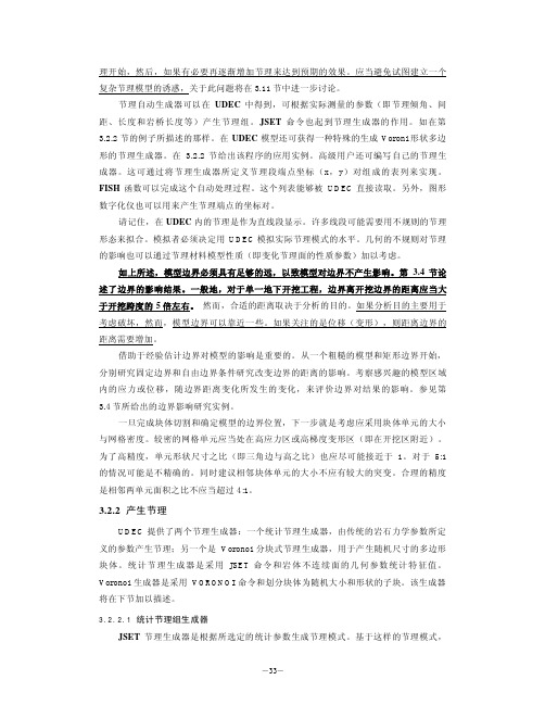
特殊 的几何 参数 对力学 特性 产生的影响 可以进行 定量 描述 。 同时,在获 得 现 场观测的节 理模 式情况下,采 用人工模 式与观 测模式 相匹配方法决定 生成的参数。 一个节理组可以通过 8 个生成参数表述: 4 个几何 参数的 均值和 4 个随机参数的均 方差 。由 JSET 命令给出 的参数如下: JSET a m、a d 、t m、t d 、g m、g d 、s m、s d < x0、y 0 >< ad 0 > 在此, a -节理与 x 轴的 夹角;
(K + 4 3 G max ∆z min
在式 中, K 、 G - 分别 是体积模量和剪 切模量;
-34-
理论与背景 第 1.1.3 节中的 range 关键词的描述。在大 部分情况下, 通过 jregion n 关键 词定义各种 区域,在此 n 是 指 定 JREGION 命令的参考序号 id。 JREGION 定义 了一个 凸多边形区域来 限制节理组的生成范围 。该命令参数如 下: JREGION id n x1 y1 x2 y2 x3 y3 x4 y4 <delete> 每 一个节理 区域是通过 id 序号识 别。区域的坐标 按顺时 针方向定义了节理产生的边 界。如果给出选择 的关键词 delete ,在此之前 由 JSET、VORONOI 或 CRACK 命令生成 的节理将 全部 被 删除。 这 可避免当指 定多 个节理 区域情况下 , 被相邻区域 产生的节理所 切割。 其他相对于 JSET 命令(即 mat n )的关键词 range 也能 用来限制 块体被 切割。如果 对 JSET 命令没 有指定范围,将产生 遍及整个区域 的节理。 JSET 生 成器也可能通过设定很大的 t m 和 s m 值用来产生贯穿 UDEC 块体的一条节 理。请记住, JSET 能够产生不连续节理。不连续节理完全处在块体里边不能看见。当 一个变形块体开始生成单元或当一个刚体模型开始运行时,所有的节理段将被删除 。 3.2.2.2 VORONOI 多边形生成器 VORONOI 生成器产生 随机大小的 多边形 块体。 UDEC 模型中的一个或 多个块体能 够 在 细 分 成 任意 大小 的 Voronoi 子 块 。 该 节理生 成器 对 模 拟 裂缝扩展 是 有 用的。当 Voronoi 块体间的节理强度 被超过 时将发生 断裂。 VORONOI 命令具有 下列形式: VORONOI edge l < iterations n> <round v> < range … > 对 于 Voronoi 多边形 指 定平 均棱 长。 多边形 具 有 随机尺寸, 但具 有 平 均棱 长 l 。 Voronoi 块体 的 大小尺寸 能够通过增加 迭代次 数 变得 均匀缺省 值 n=5 。也 能 指 定 圆 角长 度。 圆角长 度, v 必须 至少小 于块体棱长 l 的 20 倍。 当应用 VORONOI 命令时 ,多边形区域应当略大 于被细 分的块体区域。 这将抑制边 界影响。Range 关键词在产生 Voronoi 块体区域的用 法,与 JSET 命令具有 相同的方 式。 Voronoi 算法 根据 随机 分布 点 从多边形 区域 开始。然后允 许内 部点移 动。迭代 过程 运 动到这 些 点。 迭代 步 越 高 , 点 间距 越均匀 。接 下来,所有 点 产生 三角 形。 最 后, 通过 做具 有公共 边所有 三角形的 垂直平分线,生成 Voronoi 多边形。多边形在所 指定区域被 其边 界所截 取。 3.2.2.3 例子 为 了说明节理的生成过程 ,下面给出了产生节理的 几个例子。 例 3.3 四组 规则节理组 new ro 0.01 blo 0 0 0 20 20 20 20 0
K3操作手册解析
版本号:1.0密级:中级K/3项目操作手册信息科技有限公司2012年07月文档更新记录文档审核记录文档去向记录目录一、基础资料 (4)1、计量单位 (4)2、物料 (4)3、仓库 (8)4、仓位 (8)5、客户 (9)6、供应商: (10)7、部门和职员 (11)8、科目 (12)二、供应链业务 (14)1、采购管理 (14)2、销售管理 (17)3、仓库管理 (24)三、MPS及MRP计算 (26)1、 MPS计算 (26)2、 MRP计算 (32)四、MPS和MRP计划订单维护 (32)1、 MPS计划订单 (32)2、 MRP计划订单 (33)五、生产任务管理 (33)1、生产投料变更 (33)2、生产物料报废/补料 (34)3、任务单汇报/请检 (34)六、操作技巧 (35)一、基础资料1、计量单位新增计量单位“个”在K/3主界面点击【系统设置】——【基础资料】——【公共资料】——【计量单位】,点左边【计量单位】——【新增】打开计量单位组的新增界面,输入组名“个”,如图1.1.1图1.1.1然后点击【确定】,再点击右边空白后点击【新增】打开计量单位新增界面,输入代码“001”,名称“个”后点击确定。
图1.1.22、物料新增物料类别:一级类别产成品,二级类别 ODM,三级类别系列,四级类别炉头数1)、新增一级类别:【系统设置】——【基础资料】——【公共资料】——【物料】,点“新增”打开物料-新增界面,点【上级组】在代码输入‘C’,名称输入‘产成品’,如图1.2.1,然后【保存】;图1.2.1新增二级类别:点“C(产成品)”,点“新增”打开物料-新增界面,点【上级组】在代码输入‘C.D’,名称输入‘ODM’,如图1.2.2,然后【保存】;图1.2.2新增三级类别:点“D(ODM)”,点“新增”打开物料-新增界面,点【上级组】在代码输入‘C.D.81’,名称输入‘单炉、拉伸上、下盖低档炉’,如图1.2.3,然后【保存】;图1.2.3新增四级类别:点“81(单炉、拉伸上、下盖低档炉)”,点“新增”打开物料-新增界面,点【上级组】在代码输入‘C.D.81.1’,名称输入‘单炉头’,如图1.2.4,然后【保存】;图1.2.4新增物料:C.D.81.1.001,属性为配置类,使用的计量单位为台,放在二楼仓库-成品区,使用加权平均法计价,存货科目为1243,收入科目为5101成本科目为5401;在K/3主界面点击【系统设置】——【基础资料】——【公共资料】——【物料】,点【新增】打开物料新增界面,输入相应资料,如图1.2.5,图1.2.5在“物流资料”标签选择物料计价方法和相应的核算、收入、成本科目,如图1.2.6,图1.2.6在“计划资料”标签选择相应的计划策略、计划模式、订货策略,如图1.2.7,然后【保存】。
- 1、下载文档前请自行甄别文档内容的完整性,平台不提供额外的编辑、内容补充、找答案等附加服务。
- 2、"仅部分预览"的文档,不可在线预览部分如存在完整性等问题,可反馈申请退款(可完整预览的文档不适用该条件!)。
- 3、如文档侵犯您的权益,请联系客服反馈,我们会尽快为您处理(人工客服工作时间:9:00-18:30)。
Extract from the onlinecatalogUDK 3Order No.: 2775375http://eshop.phoenixcontact.de/phoenix/treeViewClick.do?UID=27753751-level terminal block with double connection on both sides, cross section: 0.2 - 2.5 mm², AWG: 30 - 12, width: 5.2 mm, color: grayhttp://Please note that the data givenhere has been taken from theonline catalog. For comprehensiveinformation and data, please referto the user documentation. TheGeneral Terms and Conditions ofUse apply to Internet downloads. Technical dataGeneralNumber of levels2Number of connections4Color grayInsulating material PAInflammability class acc. to UL 94V2DimensionsLength63.5 mmWidth 5.2 mmHeight NS 35/7,547 mmHeight NS 35/1554.5 mmHeight NS 3252.5 mmTechnical dataRated surge voltage 6 kVPollution degree3Surge voltage category IIIInsulating material group IConnection in acc. with standard IEC 60947-7-1Nominal current I N32 A (the maximum load current must not be exceeded by thetotal current of all connected conductors)Nominal voltage U N500 VConnection dataConductor cross section solid min.0.2 mm2Conductor cross section solid max. 4 mm2Conductor cross section stranded min.0.2 mm2Conductor cross section stranded max. 2.5 mm2Conductor cross section AWG/kcmil min.24Conductor cross section AWG/kcmil max12Conductor cross section stranded, with ferrule0.25 mm2without plastic sleeve min.Conductor cross section stranded, with ferrule2.5 mm2without plastic sleeve max.Conductor cross section stranded, with ferrule0.25 mm2with plastic sleeve min.Conductor cross section stranded, with ferrule2.5 mm2with plastic sleeve max.2 conductors with same cross section, solid min.0.2 mm22 conductors with same cross section, solid max. 1 mm22 conductors with same cross section, stranded0.2 mm2min.2 conductors with same cross section, stranded1.5 mm2max.2 conductors with same cross section, stranded,0.25 mm2ferrules without plastic sleeve, min.2 conductors with same cross section, stranded,1.5 mm2ferrules without plastic sleeve, max.2 conductors with same cross section, stranded,0.5 mm2TWIN ferrules with plastic sleeve, min.2 conductors with same cross section, stranded,1 mm2TWIN ferrules with plastic sleeve, max.Cross-section with insertion bridge, solid max. 2.5 mm2Cross-section with insertion bridge, stranded max. 2.5 mm2Type of connection Screw connection Stripping length8 mmInternal cylindrical gage A3Screw thread M 3Tightening torque, min0.5 NmTightening torque max0.6 NmCertificates / ApprovalsCSANominal voltage U N300 VNominal current I N20 AAWG/kcmil28-12CULNominal voltage U N300 VNominal current I N20 AAWG/kcmil30-12ULNominal voltage U N300 VNominal current I N20 AAWG/kcmil30-12Certification CSA, CUL, GOST, PRS, ULAccessoriesItem Designation DescriptionAssembly3022218CLIPFIX 35Snap-on end bracket, for 35 mm NS 35/7.5 or NS 35/15 mountingrail, can be fitted with Zack strip ZB 8 and ZB 8/27, terminal stripmarker KLM 2 and KLM, width: 9.5 mm, color: gray2775113D-UDK 4Cover, width: 1.5 mm, color: gray1201413E/UK 1End brackets, for supporting the ends of double-level and three-level terminal blocks, width: 10 mm, color: gray0201595FB-150 METER Cross connection rail, for fixed bridging of identical inputs andoutputs, made of Cu, nickel-plated, 1 m long1201028NS 32 AL UNPERF 2000MM G rail 32 mm (NS 32)1201280NS 32 CU/120QMM UNPERF2000MM G-profile DIN rail, deep-drawn, material: Copper, unperforated, height 15 mm, width 32 mm, length 2 m1201358NS 32 CU/35QMM UNPERF2000MM G-profile DIN rail, material: Copper, unperforated, height 15 mm, width 32 mm, length 2 m1201002NS 32 PERF 2000MM G-profile DIN rail, material: Steel, perforated, height 15 mm, width32 mm, length 2 m1201015NS 32 UNPERF 2000MM G-profile DIN rail, material: Steel, unperforated, height 15 mm,width 32 mm, length 2 m0801762NS 35/ 7,5 CU UNPERF2000MM DIN rail, material: Copper, unperforated, height 7.5 mm, width 35 mm, length: 2 m0801733NS 35/ 7,5 PERF 2000MM DIN rail, material: Steel, perforated, height 7.5 mm, width 35 mm,length: 2 m0801681NS 35/ 7,5 UNPERF 2000MM DIN rail, material: Steel, unperforated, height 7.5 mm, width 35mm, length: 2 m1201756NS 35/15 AL UNPERF 2000MM DIN rail, deep-drawn, high profile, unperforated, 1.5 mm thick,material: Aluminum, height 15 mm, width 35 mm, length 2 m 1201895NS 35/15 CU UNPERF 2000MM DIN rail, material: Copper, unperforated, 1.5 mm thick, height 15mm, width 35 mm, length: 2 m1201730NS 35/15 PERF 2000MM DIN rail, material: Steel, perforated, height 15 mm, width 35 mm,length: 2 m1201714NS 35/15 UNPERF 2000MM DIN rail, material: Steel, unperforated, height 15 mm, width 35mm, length: 2 m1201798NS 35/15-2,3 UNPERF 2000MM DIN rail, material: Steel, unperforated, 2.3 mm thick, height 15mm, width 35 mm, length: 2 m2770215TS-KK 3Separating plate, for electrical separation of neighboring bridges,can be fitted later, no loss of pitch, color: GrayBridges2303145EBL 2- 5Insertion bridge, 2-pos., fully insulated2303158EBL 3- 5Insertion bridge, 3-pos., fully insulated2303132EBL 10- 5Insertion bridge, 10-pos., divisible, fully insulated3000227FBRI 2-5 N Fixed bridge, for cross connections, with screws, screw headswithout insulation, 2-pos.3000201FBRI 3-5 N Fixed bridge, for cross connections, with screws, screw headswithout insulation, 3-pos.3000191FBRI 4-5 N Fixed bridge, 4-pos.2770642FBRI 10-5 N Fixed bridge, for cross connections in the terminal center, withfixed crimped rolls, screw heads with insulating collar as shockprotection, 10-pos., divisible3000434FBRI 12-5 N Fixed bridge, for cross connections in the terminal center, withfixed crimped rolls, screw heads with insulating collar as shockprotection, 12-pos.3000476FBRI 16-5 N Fixed bridge, for cross connections in the terminal center, withfixed crimped rolls, screw heads with insulating collar as shockprotection, 16-pos.3000515FBRI 20-5 N Fixed bridge, for cross connections in the terminal center, withfixed crimped rolls, screw heads with insulating collar as shockprotection, 20-pos.3006823FBRI 40-5 N Fixed bridge, for cross connections in the terminal center, withfixed crimped rolls, screw heads with insulating collar as shockprotection, 40-pos.1413230SBRN 2-7Switching bridge, 2-pos.2303239USBR 2-7Switching bridge, 2-pos.2305538USBRJ 2-7Switching bridge, for bridged terminal groups, 2-pos.Marking1007219SBS 5:UNBEDRUCKT Marker cards for modular terminal blocks, color: white1050295ZB 5:SO/CMS Zack strip, 10-section, divisible, special printing, markingaccording to customer requirementsPlug/Adapter2303543KSS 5Short circuit connector, for short circuiting neighboring terminalblocks, can only be used with PSB or PSBJ, 2-pos., pitch: 5.2 mm,color: Black0601292PSB 3/10/4Test plug socket, not insulated, length: 10 mm, screw threadwidth: 3 mm, socket width: 4 mm0201304PSBJ 3/13/4Test plug socket, insulated, length: 13 mm, screw thread width: 3mm, socket width: 4 mm, insulation material transparent 0201647RPS Reducing plug, for transition from 4 mm diameter test plug socket,insulation: grayDrawingsCircuit diagram1 = cover2 = fixed bridge, for cross-connections in the terminal center,screw heads with insulating collar3 = fixed bridge, for cross-connections in the terminal center, withcrimped-on rollers4 = insertion bridge5 = isolator bridge bar6 = bridge bar isolator7 = switch bar for 2 terminal blocks8 = separating plateAddressPHOENIX CONTACT GmbH & Co. KGFlachsmarktstr. 832825 Blomberg,GermanyPhone +49 5235 3 00Fax +49 5235 3 41200http://www.phoenixcontact.de© 2008 Phoenix ContactTechnical modifications reserved;。