Cat 4190-HV German A00--派克电子样本
霍尼韦尔空气净化电子样本

600×442×162mm
16.4kg(运输) 14kg(安装)
UL 认证
F58G 空调箱适配型电子空气净化机
特性:
• 每个单元最大处理容量2000cfm(3400m3/h) • 多个单元可组成排列的空气净化机 • 指示灯可显示正常运行及故障情形 • 可与楼宇管理系统连接使用 • 电镀的机箱可防止生锈 • 测试按钮检查系统运行 • 预过滤网保护电子单元不受大颗粒污染 • 可有效去除悬浮在空气中直径为0.3μ的微粒 • 可与紫外线灯配套应用 • 发生误操作或电子单元需要清洗时,电子继电器将停止工作 • 电子单元在相当范围内负载时,固态电源供应组合可自我调
性能参数表
型号 电子单元数量 处理风量 安装方式 面板 / 格栅形式
组成
电源 运行环境 尺寸 重量 认证
F52G1012
F52G2002
1
1000cfm (1700m3/h)
回风口型
百叶
固态电源供应组合, 电子单元,预过滤网,格栅
电子单元,预过滤网,格栅
220V/50Hz
无电源供应
40oF-125oF (4oC-52oC)
740×485×273mm
31.5kg(运输) 29.5kg(安装)
18.5kg(运输) 16kg(安装)
UL 认证
CE 认证
F57A/B 嵌入式电子空气净化机
特性:
• 三速电机驱动循环风机 F57A额定处理风量可达875cfm (1500m3/h) F57B额定处理风量可达460cfm (782m3/h)
做为整体过敏症治疗方案中的一部分,Honeywell电子空气净化机的应用可以减轻过敏症和其它呼吸问题给患 者带来的伤害。然而,并不是所有类型的空气净化机都能达到此处理效果。
瓦尔特电子样本

Anbaudosen4 Für die optimale Darstellungin Acrobat Reader unter Grundeinstellungen...Standard-Seitenlayout:Fortlaufend - Doppelseiteneinstellen.(Gerade Seitennummern links)404Eine Besonderheit ist derweiche Übergangsradius von Flansch auf Kragen für Einsatzbereiche mit erhöhten Hygieneanforderungen:• Arzneimittelindustrie • Kosmetikindustrie • Lebensmittelindustrie Leicht zu reinigen.WALTHER-Anbau-dosen von 16 - 63 A sind fingersicher nach BGV A3 (früher VGB 4), die 125 A Anbaudosen sind durch Normenmaße bedingt handrückensicher und entsprechen somit den Un-fallverhütungsvorschriften der gewerblichen Berufsge-nossenschaften sowie der DIN/VDE 0106 T 100.Anbaudose für Verteiler-schrankeinbau.Im Lieferumfang enthalten sind die Flanschabdeckung, die Gerätedose sowie die Befestigungsschrauben - also KomplettlieferungDas Foto zeigt die Prüfung mit dem …VDE-Finger“.Rückseitige Ansicht der Anbaudose:Wissenswertes über Anbaudosen41Anbaudosen, auch für Kanalinstallation IEC/EN 60 309Kanalinstallation mit CEE-Anbaudose (Mondo-Version).Erhältlich in den Farben passend zu Ihrer Installation.Die jeweils erforderlichen Kanaleinbaudosen finden Sie in den Katalogen der Her-steller von Kabelkanälen. Bitte beachten Sie deren und unsere Flansch- und Befestigungsmaße.Kanaleinbaudosen für TEHALIT Stahlblech- und Kunststoffkanäle, auch lackiert lieferbar, z.B. in Alu Silber:Anbaudosen, beschrift- undabschließbar:Anbaudosemit weichem Übergangsradius von Flansch auf Kragen, IP44. Für Einsatzbereiche mit erhöh- ten Hygieneanforderungen - leichte Reinigung.Kanalinstallation mit CEE-Anbaudose (Kragenversion).Multi-ContactSeit über 30 Jahren kommt bei allen 125 A Geräten Multi-Contact zum Einsatz.Vorteil: Deutlich geringere Steck- und Abzugskräfte sowie gleichbleibender Kontaktdruck auf Jahre hinaus.Der Multi-Contact-Kranz, bestehend aus 13 Lamellen, überträgt 28 A pro Lamelle, d.h. der Übergang von Stift auf Buchse ist für 364 A aus-gelegt - hohe Sicherheit. Lamellen sind federn gelagert und dadurchselbstreinigend.IP 44IP 44IP 44IP 44IP 44IP 44 4243AnbaudosenDie hier aufgeführten Anbaudosen in 63 A sind auch mit Pilotkontakt erhältlich.Zum Bestellen einfach …P“ hinter der Art.-Nr. einfügen!Verfügbarkeit der blau gedruckten (und der nicht aufgeführten) Frequenzen und Spannungen bis 690 V auf Anfrage !44IP 44 IP 44 IP 44 IP 44 IP 44 IP 4445AnbaudosenDie hier aufgeführten Anbaudosen in 63 A sind auch mit Pilotkontakt erhältlich.Zum Bestellen einfach …P“ hinter der Art.-Nr. einfügen!Verfügbarkeit der blau gedruckten (und der nicht aufgeführten) Frequenzen und Spannungen bis 690 V auf Anfrage !IP 67 IP 67 IP 67 IP 67 IP 67 IP 6747AnbaudosenDie hier aufgeführten Anbaudosen in 63 A und 125 A sind auch mit Pilotkontakt erhältlich.Zum Bestellen einfach …P“ hinter der Art.-Nr. einfügen!Verfügbarkeit der blau gedruckten (und der nicht aufgeführten) Frequenzen und Spannungen bis 690 V auf Anfrage !IP 44 IP 44 IP 44IP 44491) RAL 7035 lichtgrau2) RAL 9010 reinweiß (RW)3) RAL 1013 perlweiß (PW)AnbaudosenVerfügbarkeit der blau gedruckten (und der nicht aufgeführten) Frequenzen und Spannungen bis 690 V auf Anfrage !IP 44Kanaleinbaudose, IP 44Kanaleinbaudose, IP 44Kanaleinbaudose, IP 44Kanaleinbaudose, IP 44511) RAL 7035 lichtgrau4) RAL 9001 cremeweiß (CW)2) RAL 9010 reinweiß (RW) 5) Lackiert Alu (LA)3) RAL 1013 perlweiß (PW)AnbaudosenVerfügbarkeit der blau gedruckten (und der nicht aufgeführten) Frequenzen und Spannungen bis 690 V auf Anfrage !IP 44und Befestigungsmaß 60 x 60 mm, IP 44IP 44IP 44IP 4452531) RAL 1013 perlweiß2) RAL 7035 lichtgrau 3) RAL 9010 reinweißAnbaudosen。
Parker Hose 产品目录说明书
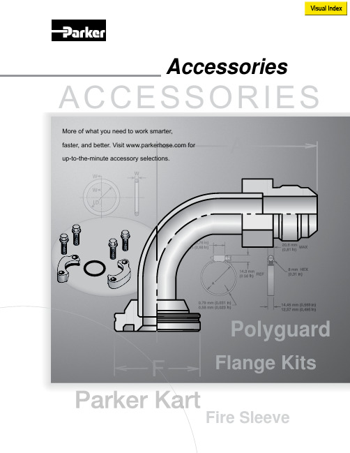
More of what you need to work smarter,AccessoriesV i s u a l I n d e x59RG D-17T1RG D-17Partek Sleeve D-18ParKoil™ (PG) D-19GuardsO-Rings for CA, CE,CF MetricFlange “D” Rings Caterpillar ® Style FlangesT ube O-Ring Fittings and CompressorFittingsO-Rings for Compression Fittings (IT126)O-Rings for C9, OC, 1C Metric Swivels88HC-H Clamp D-2488DB Clamp D-24Hose Assembly D-26Workstations3/4 Reel Rack D-2772B-Cabinet D-28HR6 Hose Bin D-28Hose Adapters D437° Flare Metric Triple-Lok ®Sizes: 6 mm – 38 mmMaterials : Steel, Stainless Steel Pressures : Up to 7200 psi60° Cone BSPPK4Sizes : 1/8” – 2”Materials : Steel Pressures : Up to 5000 psi30° Flare Komatsu StyleSizes : M14 x 1.5 – M33 x 1.5Materials : Steel Pressures : Up to 4000 psiO-Ring Face-Seal Metric Seal-Lok™Sizes: 1/4” – 2”Materials: Steel, Stainless Steel Pressures: Up to 9200 psiJapanese Industrial Standard JISSizes : 1/4” – 1”Materials : Steel Pressures : Up to 5000 psiWhen ordering Parker Adapters, please state the Catalogued Number of each type of adapter desired. Be sure to double check tube and hose sizes of items required.To select proper seal materials for specific applications, refer to Media Compatibility Chart in Tube Fitting Catalog 4300, or contact your Parker Tube Fitting Distributor.If in doubt about which type or size of fitting to specify, consult your Parker Tube Fitting Distributor. In addition Parker Field Sales, Technical Services,the Tube Fitting Division and your local Parker Service Center will help you find answers to all your issues.Phone: (614) 279-7070Fax: (614) 279-7685Web: /tfdNote: Refer to Parker Catalog 4300 for more detailed application information.CALL TOLL-FREE 1-800-C PARKER (1-800-272-7537)Parker Information Center for catalogs, literature or additional information.O-Ring Face-Seal Seal-Lok™ Sizes: 6 mm – 38 mm Materials: Steel, Stainless Steel Pressures: Up to 9200 psi37° Flare FittingsTriple-Lok ®Sizes: 1/8” – 2”Materials: Steel, Stainless Steel, BrassPressures: Up to 9000 psiPipe Fittings and Port AdaptersSizes: 1/8” – 2”Materials : Steel, Stainless Steel, BrassPressures : Up to 7200 psiPipe SwivelsSizes : 1/8” – 2”Materials : Steel, Stainless Steel Pressures : Up to 5000 psiConversion AdaptersSizes: 1/4” – 1-1/2”Materials : Steel, Stainless Steel Pressures : Up to 7700 psiHydraulic Flange and Flange AdaptersSizes : 3/4” – 3”Materials : Steel, Stainless Steel Pressures : Up to 6000 psi15T3SAE (Code 61) Flange – Male SAE (JIC) 37˚ FlareCaution: Do not use the T3 flange to tube or swivel nut to tube adapter in hose assembly applications inwhich pressures exceed the SAE100R2 working pressure range.17T3SAE (Code 61) Flange – Male SAE (JIC) 37˚ Flare - 45˚ Elbow19T3SAE (Code 61) Flange – Male SAE (JIC) 37˚ Flare - 90˚ Elbow39T3Male - Female Swivel - SAE (JIC) 37˚ - 90˚ Elbow41T3Male - Female Swivel - SAE (JIC) 37˚ - 90˚ Elbow - Long4AH3SAE Code 61 Flange - Male SAE (JIC) 37˚ Flare - 5000 psi Caution: Do not use the T3 flange to tube or swivel nut to tube adapter in hose assembly applications in which pressures exceed the SAE100R2 working pressure range.4FH3SAE Code 61 Flange - Male SAE (JIC) 37˚ Flare - 5000 psi -45˚ Elbow4NH3SAE Code 61 Flange - Male SAE (JIC) 37˚ Flare - 5000 psi -90˚ Elbow6AH3SAE Code 62 Flange - Male SAE (JIC) 37˚ Flare6FH3SAE Code 62 Flange - Male SAE (JIC) 37˚ Flare - 45˚ Elbow4AJMCode 61 Flange - Male Seal-Lok4FJMCode 61 Flange - Male Seal-Lok - 45˚ Elbow4NJMCode 61 Flange - Male Seal-Lok - 90˚ Elbow6NH3SAE Code 62 Flange - Male SAE (JIC) 37˚ Flare - 90˚ Elbow6NJMCode 62 Flange - Male Seal-Lok - 90˚ Elbow6FJMCode 62 Flange - Male Seal-Lok - 45˚ Elbow6AJMCode 62 Flange - Male Seal-LokNote:*5000 psi with 4A, 4F and 4N Fittings and 50H Flange Halves.There are two non-interchangeable SAE split flanges: a: S tandard or Code 61 is for 3,000psi to 5,000psi maximum, depending on size.b.H igh Pressure or Code 62 is for 6,000psi maximum, r egardless of size. The flange head is “V” notched for identification.Consult these tables to determine flange halves and flange kits specifications.High Pressure (Code 62)Standard Pressure (Code 61)Note: For use with 4A, 4F and 4N Flanges.50H5000 psi Flange Half (Code 61)Note: For use with 4A, 4F and 4N Flanges.Note: High pressure applications also require the use of Code 61 Flange End hose fittings.51HSAE Flange Half (Code 61)5050HK5000 psi Flange Kit (Code 61)5151HKSAE Flange Kit (Code 61)HFHSAE Flange Half (Code 62) HFHFHKSAE Flange Kit (Code 62) 8FHFlange Half (8000 psi)8FHFHKFlange Kit (8000 psi)DIN and ISO Metric PortsDIN (German) and ISO (International Organization for Standardization) flange heads are the same as SAE flange heads. By comparison, the ports have the same configura-tion except that the DIN and ISO Type I ports accept metric bolts. This requires specialflange halves in most sizes.Note: High pressure applications also require the use of Code 62 Flange End hose fittings.M1HDIN (ISO) Flange HalfM1M1HKDIN (ISO) Flange Kit (Code 61)M2M2HKDIN (ISO) Flange Kit (Code 62)M2HDIN (ISO) Flange Half (Code 62)711509O-Rings - SAE Thread (Compound N552-90)*711510O-Rings - Code 61 and Code 62 Flanges (Compound N552-90)**Note: F or use with petroleum base fluids, other compounds available for Phosphate Ester fluids.Please contact The Parker Hannifin Seal Group/O-Ring Division (1-800-C-PARKER) for additional information.C9RG O-Rings for CA, CE, CF MetricC9RG O-Rings for C9, OC, 1C Metric SwivelsD9DTBonded Seal for BSPP Port Fittings*Note: D 9DT must be ordered from the Tube FittingsDivision. Please contact TFD for additional size and product information.XARGFlange “D” Rings Caterpillar ®Style FlangesJ0RGO-Rings - Seal-Lok ®Note: O -Rings for use in Seal-Lok ® connections are illustrated in actual size. Part numbers for O-Ringsused in Seal-Lok ® and in SAE port connections are also listed in the table. O-Rings are supplied in Nitrile NBR compound, 90 durometer hardness.SAE 711509-4-8Seal-Lok J0RG-8-8Photo shows an actual comparison between an SAE port O-Ring (top) and a Seal-Lok ® O-Ring (bottom). They differ in both diameter and cross section.8ARGFlange “D” Rings for 76 Series Style FlangeT1RGO-Rings for Compression Fittings (1T126)Charge Ports CapsR134aR12CORGCaptive O-Ring Assembly ToolsParker’s new CORG Assembly Tools are designed to facilitate the installation of the O-Ring into the half-dovetail groove of the O-Ring face seal fitting.Note: C ORG Assembly T ools must be ordered from the T ube Fittings Division (614) 279-7070.Note: O -Rings listed are for use with petroleum base fluids. Other compounds are available for Phosphate Ester fluids by special order. For Viton ® or otherO-Ring compounds, consult Parker Hannifin, Seal/O-Rings Products Division (1-800-C-PARKER.)Bench TypeHand Type59RGO-Rings for Tube O-Ring Fittingsand Compressor FittingsNote:T he above O-Rings (RG) have HNBR compound number N1195-70 (green).Accessory Selection Guide – Partek Sleeve (AS-B, AS-Y or PS)Note: T he inside flat “A” dimension correspondswith the inside diameter “B” dimension. For example, AS-Y -13 flat surface “A” is 1.34 in. This offers a .86 in. inside diam-eter “B”. Hose with a smaller O.D. can be specified for this size sleeve. Parker 201-5 hose has a .58 in. O.D. and can easily be inserted in the Partek AS-Y -13Sleeve.Note: 1. T he dimensions shown are related to the hose outside diameter and may not fit over the fitting. For over the fitting applications, a larger sizesleeve may be required.2. Cut lengths are available. Contact your local distributor for prices ().Partek SleevePartek “PS” SleeveParker’s Partek Nylon Protective Sleeving gives you tough hose abrasion protection two ways. First, per the ISO 6945 specification, Partek has a unique tubular weave nylon construction, Partek “AS” is strong enough to withstand greater than 200,000 abrasion cycles without wearing through the fabric at any loca-tion. Partek “PS” can withstand greater than 50,000 abrasion cycles. In addition, this weave also gives an exceptionally smooth interior wall, allowing rubber hose to move freely inside the sleeve. This provides easy installation and prevents any internal abrasion problems. Partek sleeving is available in either black or yellow and in sizes to fit most hydraulic hose. Partek, the quick and easy solution to hose protection in high-abrasion areas.Temperature Range: -67°F to +248°F (-53°C to +120°C)Accessory Selection Guide – PolyGuard (HG)• S hield hose from abrasion and cuts • Minimize kinking• Cannot rust or corrode • R esist water, oil, gasoline, hydraulic fluid, and most solvents • I deal for bundling plastic tubing or hose lines • E asy to install without removing hose lines; no clamps neededPolyGuardHeavy-duty polyethylene provides protection in rugged operating conditions.Great for b undling high-pressure hose lines.Cut edges can be smoothed by applying heat.CAUTION: This material will support combustion.Color: BlackTemperature Range:0˚F to +200˚F (-17˚C to +93˚C)Parkoil ™Lower-cost protection for applications that call for a tighter bend radius and are less demanding.Cut edges can be smoothed by applying heat.CAUTION: This material will support combustion.Color: BlackTemperature Range:0˚F to +200˚F (-17˚C to +93˚C)Accessory Selection Guide – ParKoil ™ (PG)Accessory Selection Guide – Spring Guard and Armor GuardNote:Spring Guard and Armor Guard are packaged in 10 ft. pieces.Parker Spring Guard and Armor Guard are two products that prolong the life of hose lines that are exposed to rugged operating conditions. They distribute bending radii to avoid kinking in hose lines and protect hose from abrasion and deep cuts. Guards areconstructed of steel wire and plated to resist rust.Spring Guard (SG)Armor Guard (AG)Accessory Selection Guide – Firesleeve (FS-F)Parker Firesleeve is a flame resistant sheath that protects the hose from extreme temperature conditions. Firesleeve easily slides over hoses and readily expands over fitting. It can be assembled with Parker FSC or properly sized wormgear clamp.Construction: Braided fiberglass sleeve and an orange,bonded and seamless silicone rubber cover.Specifications: Conforms to SAE Aerospace Standard 1072A Type 2A.Temperature Range:-54˚C to +260˚C (-65˚F to +500˚F).Note: T he Firesleeve inside dimension (I.D.)must exceed the outside diameter (O.D.) of the hose and offer an allowance for easy hose insertion. For example, 201-16 has a 1.23 in. O.D. FS-S-24, with an I.D. of 1.46 in., is the suggested Firesleeve. Note: P arker FSC Clamp fits all hoses up to2 in. O.D. Note: P arker HC Clamps (wormgear) are listedon page D-24.Note: See Page D-22 for Firesleeve assembly instructions.Firesleeve (FS-F)FSC ClampPart Number: FSC(One size fits all hoses up to 2 inch O.D.)Accessory Selection Guide – Firesleeve (cont.)1. A ssemble one end fitting on hose. Cut firesleeve to same length as hose. Cover approximately 1” of each end of fire-sleeve with FSS sealant and allow to dry.2. P ush firesleeve back from cut end of hose and assemble the second end fitting. Then pull firesleeve completely over both sockets.3. I nsert tail of FSC clamp into FST clamping tool.4. P osition clamp around middle of socket and tighten with tool. Bend end of band back over buckle. Repeat on other end.Repair any scuffs or abrasions in firesleeve with FSS sealant.FSC ClampUsed to attach firesleeve around socket on hose sizes with a 2” maximum O.D.FST Clamp ToolPart Number: FST -711617 Used to secure FSC clamp.FSS Firesleeve SealantKeeps end of firesleeve from fraying - for neater, longer lasting installation.FiresleeveAssembly InstructionsAccessory Selection Guide – CL ClampVinyl coated steel clamps provide hose support where long lengths are used. Provides neater installation of hose lines, minimizes hose chafing and prevents damage to hose.Material: CR Steel with Zinc PlatingCoating: Black Vinyl Plastisol - 0,8 mm (0.03 inch) thick.Temperature Range:-40°C to +107°C (-40°F to +225°F).Accessory Selection Guide – HC, 88HC-H and 88DB ClampThe Parker HC Clamp is a stainless steel worm gear clamp designed for low presure industrial hose applications.Material: Stainless steelSpecifications: SAE J1508, Type F and Type HD88HC-HSeries Hose Clamp(High Torque Wormgear)88DBSeries Heavy Duty Hose Clamp(Double Bolt Hose Clamp)HC Hose Clamp TableNote: See 88 Series Assembly Instructions for proper 88HC-H clamp attachment.Accessory Selection Guide – Protection Shields (HP , HT, and HP-B)Prevent hose abrasion while extending your hose life. Parker Hose Protection Shields extend hose life by protecting the hose from abrasion that occurs when hose rubs against other hose, metal or concrete. Parker hose shields are resistant to oil, lubricants, gasoline, most solvents and can withstand ambient temperatures from -40° to +300° F . Easily installed and secured by cable ties without disconnect-ing any hose lines. Use with hose from 1/4” to 2” I.D.♦ Eliminate hose abrasion on concrete, metal or any rough surface. ♦ Guard against hose deterioration on mobile hydraulic equipment. ♦Let Parker fill all your hydraulic and pneumatic hose product needs.Hose Protector Shields are a fast and extremely cost effective way to isolate fluid lines from direct contact with other lines, components or structural members. They’re available in 4-inch, 6-inch and 8-inch lengths and the width can be trimmed to satisfy a variety of situations. These flexible protectors simply clamp around the hose and are securely held in place by nylon cable ties which are included. The cable ties are recessed in molded grooves to protect them from abrasion. You don’t need to disconnect a line to install a Parker Hose Protector Shield the way you do with a continuous tubular sleeve. Just wait until the installation is up and running to see exactly where contact needs to be prevented.Parker Hose Protector Shields are available in bulk quantities and in convenient assortments in 4”, 6” and 8” sizes. Cable ties are included with all protectors and are also available in bulk.Hose ShieldsTie Wraps HP-B-13X18-KIT2 ea. HP-13 RFL HT -12-KIT 30 ea. HT -12 Tie Wraps 2 ea. HP-15 RFL HT -16-KIT 30 ea. HT -16 Tie Wraps4 ea. HP-18 RFLHT -22-KIT15 ea. HT -22 Tie Wraps20 Hose Protectors and 60 Tie Wraps for each size are in point of purchase display box.HP-B-13-RFL 10 ea. HP-B-13 Hose Protectors (4”). 30 ea. HT -12 Tie Wraps in a sealed plastic bag.HP-B-15-RFL10 ea. HP-B-15 Hose Protectors (6”). 30 ea. HT -16 Tie Wraps in a sealed plastic bag.HP-B-18-RFL5 ea. HP-B-18 Hose Protectors (8”). 15 ea. HT -22 Tie Wraps in a sealed plastic bag.Contact your authorized Parker Hose Products Distributor for pricing and delivery information.Note: Parker Hose Protector Shield products are intended to prevent damage. They are not suitable as patches or repairs for lines which are already damaged or worn beyond safe use standards.Counter DisplayThe complete on-site complete hose assembly workstation design (above) includes:• TH7-5-C—6’ table with 1 hose reel and 1 bottom shelf • TH7-6—16 hose reel system, with rotating base • T H7-7—15” wide table set up for Parker 239 or 339 Cut-Off Saw Specifications: HoseFab Table (heavy duty)• Laminated wood table top • 1-1/2” square tubing structure • Gussetted corner braces • 6-leg design• All legs have adjustable feet • Hose reel/shelf combinations• 40B-Cabinet or 72B-Cabinet for fitting storage • Optional: Hose trough for measurement of hose • Calibrated to line up to Saw Table • Adjustable stop for standard length cuts• Built-in tape measureSpecifications: Rotary Reel Rack (TH7-6)• 16 Hose reel capacity • Compact design• Rotates for 1 man use• Center post bolts to floor in 4 places • Optional: Overhead craneSpecifications: Saw Table (TH7-7)• Calibrated to line up to Hose trough • Adjustable feet• Mounts to 6-foot benchSpecifications: 3 or 4 Reel Rack • Free standing 3 reel rack (TH7-8)• Bolts to floor• Optional: 4th reel capacity with wall mounts (TH7-8-F)• (2) 40B-Cabinet 40 openings - 4·1/2” x 4·1/2” x 12” in size • TH7-6-C—Optional overhead crane • T H7-5-HT—Optional 6’ measured hose trough with ad -justable hose stopPictured left is a complete on-site hose assembly workstation, the Parker Kart:The Parker Kart, TH7-4, is a portable all-in-one unit designed to hold a Minikrimp, Karrykrimp, Karrykrimp 2, or Parkrimp 1; a 332T -115V Cut-off Saw; 4 reels of hose; and has a 40 bin cabinet with 3 drawers for tools. The TH7-4 can be customized to fit your specific hose assembly needs. Contact Parker HPD or your Parker Hose distributor for details.Note: Part number TH7-4 does not include hose, fittings or equipment.Note: Part number and specifications of components for both workstations are listed on the following pages.HPD Hose Assembly WorkstationsHose Products Division has set up an agreement to allow Hose Products customers to purchase directly from our vendor, Safety Step.Safety Step’s contact information is:Safety Step Annette Cox 888-448-4237*********************See Safety Step contact information at the top of this pageSaw TableFeaturesThe Saw Table, specially designed for Parker 239 or 339 Hose Cut-Off Saw, attaches directly to the HoseFab Table.Part Number DescriptionTH7-715” wide table set up for Parker 239 or 339 Cut-Off Saw Table measurements:H eight - 18” Width - 28”Length - 14”3/4 Reel RackFeaturesCompact in its design, the standard version will hold 3 reels of hose. Optional 4th reel capacity designed with wall anchor mounts.P art Number DescriptionTH7-8 Upright 3 hose reel rackTH7-8-FO ptional extension with wall anchor for 4th reel Rack measurements:Height - 59” (82·1/2” with 4th reel option) Width - 27·3/4”Length - 27·1/2”HoseFab TableFeaturesHeavy duty constructed table for mounting Minikrimp, Karrykrimp, Karrykrimp 2, or Parkrimp 1. HoseFab Table is available in 3 versions to meet your require-ments. Options include two 40B-Cabinets or 72B-Cabinets for fitting storage.Part Number Description TH7-5-R 6’ table with 2 hose reels TH7-5-S 6’ table with 2 bottom shelves TH7-5-C 6’ table with 1 hose reel and 1 bottom shelf TH7-5-HT O ptional 6’ measured hose trough with adjustable hose stop 40B-Cabinet 40 openings - 4·1/2” x 4·1/2” x 12” in size 72B-Cabinet 72 openings - 4·1/2” x 4·1/2” x 12” in size Table measurements: Height - 31-3/4” Width - 29”Length - 72”Rotary Reel RackFeatures16 Hose reel capacity that fits in a compact area. Supplied with heavy duty casters which allow for ease of turning, even when fully loaded. Optional overhead crane available.Part Number DescriptionTH7-6 16 hose reel system, with rotating base TH7-6-C Optional overhead craneRack measurements:Height - 104” (120” with optional overhead crane) Width - 67”Length - 67”See Safety Step contact information on page D-26See Safety Step contact information on page D-26See Safety Step contact information on page D-26See Safety Step contact information on page D-26Parker Kart Part No. TH7-4Parker Kart organizes and stores all your necessary Parker hoses, fittings, power and hand tools - everything you need to make fast hose assemblies on site. As a valued addition to any facility, Parker Kart will save on downtime and labor costs, as well as eliminate errors in cutting and fitting attachment. With Parker Kart, you’ll always have the materials you need, right when and where you need them.• Easy one-man movement• Eight-inch urethane casters with brakes• Forklift carry tubes• Electric receptable with cord• Fitting bins and drawers• Large tool drawer• Four hose reel holders• Choice of Parker crimping equipment• Optional accessories availableParker Kart can be customized to fit specific hose assem-bly needs. Parker Kart does not include hose, fittings orequipment.Fitting Stock Bins72B-Cabinet36” wide, 43” high, 12” deep, with 72 openings each 4-1/2”x 4-1/2” x 12”, heavy duty steel, all welded construction.Product bin labels are available.Hose Stock BinsHR6-Hose-BinRugged metal cabinet for stocking coils of Parker hose 36”wide, 28” high, 20” deep, with upright separators to provide6 compartments varying in width from 4” to 8”.Provides suitable base on which to place the fittings stockbin (top measures 36” x 20”, bottom of fittings bin measures36” x 12”.)Yellow with black “Parker Hose” lettering.See Safety Step contact information on page D-26。
Parker Hannifin 电子传感器和 Reed 传感器产品介绍说明书

Electronic SensorsContents - /pneu/actuators Catalog 0900P-7Parker PneumaticElectronic and Reed Sensors Product Overview L2Technical Data L3DimensionsL4Connection Type and Diagram L5Ordering Information L6Continuous Position Sensors Product Overview L7Techncal Data L8DimensionsL9Connection Type and Diagram L9Ordering Information L9AccessoriesMounting and Brackets L10Connectors and CablesL11Pneumatic Sensor for Tie Rod Cylinders Product Overview L12Techncal Data L12DimensionsL12Product OverviewThe P8S Series magnetic cylinder sensor enables quick, precise and contactless sensing of the piston’s position in cylinders. It is easy to mount, can be used in numerous applications and offers an outstanding price-performance ratio.Product OverviewAs the term magnetic switch suggests, these are operated by magnetic fields; another description widely used is magnetic “SENSOR”. As our eyes sense change of light, our ears sense the change of sound, magnetic sensors / switches sense the change of magnetic flux in pneumatic and hydraulic cylinders. When magnetic sensors sense a magnetic field it will give a switching signal, through a control circuit, allowing sensing or control operation to be achieved.Because of the characteristics of magnetic sensors they can sense a change of magnetic field relative to the position of the magnet, such as in a pneumatic or hydraulic cylinder, whereby the magnet is attached to a moving piston and thus the position of the moving part (ie Piston) can be detected. The magnet is mounted on the piston of the cylinder and thus moves with the piston.The magnetic sensor (switch) is fixed either directly to the cylinder or with an additional mounting bracket. When the piston (magnet) moves to the position under a magnetic sensor, the switch will operate due to the change of the magnetic field and give a switching signal.Thus the position of the piston can be identified and a resulting signal generated to continue the sequence of a circuit.Magnetic sensors available can be classified into two different groups, they are sensors with contacts which are called mechanically operated or reed sensors and the other type is sensors without contacts and are called solid state type or electronic.Parker P8S Series sensors are suitable for use with a large range of actuators. They can either be inserted directly into the cylinder tube extrusion or mounted using additional brackets. For direct mounting the sensor is positioned within the cylinder sensor groove, offering mechanical protection, then securely clamped into position by a simple turn of a screw. For other cylinder versions there are a number of optional sensors brackets that clamp to the cylinder and offer other mounting positions.For easy installation there are several cable lengths available with either M8 connector or flying lead. The electronic sensors are “Solid State”, i.e. they have no moving parts. They are provided with short-circuit protection and transient protection as standard. The built-in electronics make the sensors suitable for applications with high on and off switching frequency where long service life is required.Please note that for low temperature applications sensors are normally specified for full performance down to -30°C only. High temperature cylinders do not have a magnetic piston and therefore cannot be used with sensors.P8S Electronic and Reed SensorsDimensions, mm (inch)PNP, NPN Output 10 to 30 V DC Reed Output 5 to 230 V AC/DCScrew 1/4 turnConnection Type and DiagramPNP NONPN NO NPN NCReed NO 3-wirePin assignment, M8 with knurled nut bn: brown bk: black bu: blue Q: load M: Mass L+: PowerPNP NCReed NO 2-wireReed NC 2-wire+ -Q NAMUR NO ATEX 1G, 1DPNP NO ATEX 3G, 3DFlying leads4 (out)3 (-)1 (+)bnbubkConnectionsSquare body design, insert straight in T-slot, screw 1/4 turnNote:-30 to +80 °C (PUR cable) I -30 to + 70 °C (PVC cable) I -25 to +80 °C (NAMUR 1GD I -20 to +50 °C (ATEX 3GD) All sensors come with an adapter for S-dovetail Parker type OSP grooves. * with an aluminium adapterOrdering InformationMany applications require more than just end of stroke sensing of an actuator, but traditional methods of continuous sensing are expensive to implement. Parker’s CPS (Continuous Position Sensor) enables quick, precise and contactless continuous position sensing of a magnetic piston.CPS sensors continuously supply data via analog outputs or IO-Link. Analog position sensors have a voltage output of 0 V ... 10 V as well as a current output of 4 mA ... 20 mA. CPS enables flexible machine concepts, making it possible to solve tasks in areas such as quality monitoring and process control in conjunction with pneumatic cylinders. This continuous transfer of position data upgrades the functionality of the pneumatic cylinders by making them more intelligent, and as a result, more versatile. CPS settings can be adjusted during or after installation using a teach button or using IO-Link.CPS can be mounted directly in standard T -slots without the need for additional accessories. Mounting on other cylinder types, (round, tie rod) is possible with adapters.• Continuous position sensing• IO-Link communication with M12 connector • No modification to the actuator • Analog version with M8 connector• 5 sizes with sensing ranges from 32 mm to 256 mm • IP67 design suitable for any industrial application • Yellow teach button for easy set-upTechnical specification:1 ms sampling rate0.03% full scale resolution 0.06% full scale repeatability 0.3 mm Linearity errorHow it works:The CPS product detects the position of an actuator via the magnet on the piston. The sensor settings can easily be adjusted during installation using the yellow teach button or during operation over the IO-Link communication. This upgrades the functionality of the pneumatic actuator by making it more intelligent and versatile in support of the Industry 4.0 initiative.How it connects:Analog version has a M8 connector and a voltage output of 0-10V as well as a current output of 4-20mA. IO-Link version has a M12 connector and transmits position via 2 bytes of process input data and also allows for parameter control of measuring range and locking of the teach button.It can be controlled by Class A or Class B IO-Link Masters.Without Adapter:Direct drop-in T -slotT-slot dimensions [mm ± 0.1]1) Pivot sensor into the slot2) Teach the CPS unit the desired measuring range 3) Tighten set screws5.554.806.803.40How it installs:The Parker CPS requires the use of a magnetic piston. The product will ft T -slot cylinders without any additional mounting hardware.Product OverviewP8S Continuous Position Sensors1) ± 1 mm 2)Reverse-polarity protected, operation in short-circuit protected network: max. 8 A. 3) Without load 4)Power output, at 24 V 5)Voltage output6) FSR: Full Scale Range;max. measuring range. 7)At 25°C, linearity error (maximum deviation)depending on response curve and minimal deviation function. 8)At 25°C, repeatability magnet movement in one direction. 9)Only in standard mode, not in IO-Link mode. 10)The analogue measured value can deviateunder transient conditions.Installation: Drop in, fixed by allen key 1.5 mm Measuring range:32 to 256 mm depending on type 1)Housing length:45 to 269 mm depending on type Output Function: Analog | IO-Link Analog output (voltage):0 to 10 V | -Analog output (current): 4 to 20 mA | -Teach-in:YesEnclosure rating:IP 67 (according to EN 60529)Supply Voltage: 2)15 to 30 V DCPower consumption: 3)<= 22 mA (analog) | <= 25 ma (IO-Link)Max load resistance: 4)<= 500 ΩMin load resistance: 5)<= 2 kΩProtection class:III Time delay before availability: 1.5 sRequired magnetic field sensitivity: 3 mT / 2 mT (analog) | 3 mT (IO-Link)Resolution: 6)0.03% full scale range (max >=0.05 mm)Linearity error: 7) 0.3 mmRepeat accuracy: 8)0.06% full scale range (>= 0.1 mm)Sampling rate: 9)1 msIndication LED color: Yellow (analog)Reserve polarity protection:Yes (analog)Short circuit protection:Yes (analog)Ambient operating temperature range:-20 to +70 °C (PUR cable)Shock and vibration resistance:30 g 11 ms / 10 … 55 Hz, 1 mm EMC: 10)According to EN 60947-5-2International standard:CE | C UL US | CCC (not applicable) | RoHs | IO-Link UL file No:On requestHousing material:Plastic polyamid PA12Screw material: Stainless steel Cable material:PUR (Polyurethane)Conductor cross-section:0.08 mm²Connector:M12 (IO-Link) or M8 (analog)TechnicalDimensions, mm (inch)Connection Type and DiagramPart NumberL1L2 *L3Analog IO-Link 453240P8SAGACHA P8SAGHMHA 776472P8SAGACHB P8SAGHMHB 141128136P8SAGACHD P8SAGHMHD 205192200P8SAGACHF P8SAGHMHF269256264P8SAGACHHP8SAGHMHH*L2 equal to the measuring range.OutputMeasuring Length ConfigurationOptionPart Number Weight [g]For Product SeriesAnalog32 mm Teach ButtonP8SAGACHA 16With T -slot groove *64 mmP8SAGACHB 26128 mm P8SAGACHD 46192 mm P8SAGACHF 66256 mm P8SAGACHH 86IO-Link32 mm Teach Button or IO-Link parameter P8SAGHMHA 20With T -slot groove *64 mmP8SAGHMHB 30128 mm P8SAGHMHD 50192 mm P8SAGHMHF 70256 mmP8SAGHMHH90* Required magnetic field sensitivity: 3mT / -2 mT (Analog) / 3mT (IO-Link) Note:PUR cable with M12 (IO-Link) or M8 (Analog) male connector knurled nut, 4-pin, 0,3 meter length. Please consult for measuring range 96, 160 & 224 mm.Ordering Information, Drop-in T-slotNote:PUR cable with M12 (IO-Link) or M8 (Analog) male connector knurled nut, 4-pin, 0,3 meter length. Please consult for measuring range 96, 160 & 224 mm.IO Link version PUR 0.3 meter length with M12 male connector knurled nut, 4-pin PUR 0.3 meter length with M8 male connector knurled nut, 4-pinbrn wht blk bluAnalog versionbrn blk whtbluDimensions, Ordering InformationFor Products SeriesPart Number Weight [g]Tie rods, 4MA, P1F , P1D, PTR, 2MNR P8S-TMAOX 65Tie rods, P1F-T Ø 32-100P8S-TMA0710Tie rods, P1F-T Ø 125-320P8S-TMA0832T -Slot OSP Ø 108872FIL 3T -Slot 2002 Series Ø 168865FIL 4T -Slot 2002/P120 Series Ø 25-808866FIL 5Round cylinder Ø10-25P8S-TMC0127Round cylinder Ø 32-63P8S-TMC0229Round cylinder Ø 80-125P8S-TMC0332S-Dovetail OSP , pack of 10P8S-TMA0910Ambient temperature -30 to +80 °CP8S-TMC01, 02 & 03Part number D [mm]P8S-TMC018 to 25Clamping ring in nickel silver, screw in stainless steel, sensor mounting zinc diecastP8S-TMC0232 to 63P8S-TMC0380 to 130All mountings can be moved on the cylinder body before screwing in place and then putting sensors in the slots.P8S-TMAOX(Zinc diecast, zinc plated screws.)Ø min. 5 (.2);1 Sensoradapter with T-slot 2 Fixing for cable < Ø 3.2 mm (0.126 inch)3 Cylinderadapter 3 Mounting screws M5Dimensions, mm (inch)Mountings and Brackets① Sensor adapter with T -Slot ② Fixing for cable < Ø 3.2 mm (0.126 inch)③ Cylinder adapter ④ Mounting screws M5Tie Rod Bracket Assembly is necessary for Global and Mini-Global Sensor installation on all tie rod construction cylinders. This includes all Intermediate Trunnion mounts (Style DD or MT4); and all 6"-8" bore Sensors and bracket assemblies must be ordered separately.Part number P8S-TMAOX fits 1-1/2" to 8" bores and32-200mm bores for Global SensorsP8S-TMAOXTie Rod Bracket AssemblyCatalog 0900P-7AccessoriesElectronic SensorsMountings and Brackets(Revised 05-06-21)Cable connectors for producting your own connecting cables.The conncectors can be quickly attached to the cable without special tools. Only the outer sheath of the cable is removed. The connectors are available for M8 screw connector and meet protection class IP65.Male Connectors for Connecting CablesOpertaing current per contact:max. 4 AConnection cross section:0.25... 0.5 mm² (conductor diameter min 0.1 mm)Protection class:IP65 and IP67 when plugged and screwed down (EN 60529)Temperature range:- 25... + 85°CDescriptionPart Number Weight [g]For Product Series Cable flex PVC 3 meter with 8mm snap-in connector / flying leads 912634434170P8S Sensors with M8Cable flex PVC 10 meter with 8mm snap-in connector / flying leads 9126344342210P8S Sensors with M8Cable PUR 3 meter with 8mm snap-in female connector / flying leads 912634434570P8S Sensors with M8Cable flex PUR 10 meter with 8mm snap-in connector / flying leads 9126344346210P8S Sensors with M8Cable PVC 5 meter with M8 screw female connector / flying leads KC3104120P8S Sensors with knurled M8*Note: not applicable for P8S CPS Sensors as no cable availableCables to extend cable sensor lengths with M8*Connector Weight [kg] Part numberM8 screw connector P8CS0803J M12 screw connector0.022P8CS1204JCatalog 0900P-7AccessoriesElectronic SensorsMale Connectors and Cables(Revised 06-19-21)Pneumatic Sensor for Tie-Rods CylindersAn ideal solution where a direct pneumatic signal is wanted from a cylinder sensor to a pneumatic control system, for example. This could be a machine or device in which only compressed air is available, and an electricity supply to normal cylinder sensors would involve serious problems or considerable expense.Function:Non-contacting sensing of a pneumatic cylinder, triggering an output signal (conn. 2) from the integrated 3/2 NC valve, which is activated by a magnetic field or iron core and has a return spring.If more than one sensor is used with a cylinder there must be a distance of at least 20 mm between sensors to prevent them influencing each other.To avoid interference, there must be a minimum spacing of 15 mm to steel details.The outlet (conn. 3) must not be blocked or restricted as this can impair the function of the sensor.The sensor is fastened to the cylinder using the special sensor fixing.Technical data:Working pressure: min 2 to max 6 bar Temperature: -15 to +60 °CAir quality: 3.4.3 to ISO 8573-1 (must be oil free)Function: 3/2 NC valve Flow:40 Nl per minuteConnection: for plastic pipe with 2,5-3 mm internal diameterActivation distance: for magnet: min 9 mm Activation distance: for Fe: approx. 2 mm Repetition accuracy: +/- 0.2 mmCylinder velocity:max 1 m/s (depends on magnetic field, interference from steel in environment, signal length requirement from control system….)Distance between sensors: min 20 mmDistance from sensor to steel details: min 15 mmFixing: with sensor fixing or with an M4 thread in caseSensing:non-contacting (also through awall of non-magnetic material)Cylinder fixing -Tie-Rod Cylinders Ø 32 to 100 mmDimensions (mm)iron coreCatalog 0900P-7TechnicalElectronic Sensors Pneumatic SensorsDescription Weight (kg)Part Number Pneumatic sensor0.02P8S-A34X Cylinder fixing bore Ø32to Ø125 mm0.01P8S-AMA1。
黑金刚
高 信 形状
品
薄 型 化
波 化
命
赖 性
工作上限温度· 标准寿命 (hours)
额定电压范围 (Vdc)
105℃超小型化品 85℃小型化品 105℃小型化品 85℃小型化标准品 105℃小型化标准品 105℃小型化标准品 85℃标准品(160Vdc以上请参照No585公报) 105℃标准品(160Vdc以上请参照No585公报) 85℃高15mm薄型品 105℃高15mm薄型品 小型化长寿命品 105℃小型化长寿命品 小型化长寿命品 长寿命品 对应异常电压·小型化高纹波品 对应异常电压·小型化品 伺服·变频器用充放电对应品(详情请参照No781公报) 85℃标准品 105℃标准品 85℃变频器高纹波小型化品 变频器用高纹波品 变频器用高耐压小型化品 变频器用高耐压品 变频器用高纹波品 变频器用长寿命品 椭圆形状·变频器用高纹波品 105℃高耐压·变频器用长寿命品 105℃变频器用高纹波长寿命品 伺服·变频器用充放电对应品(详情请参照No782公报)
铝电解电容器
产品指南
接前页
标 准
小 型 ·
低
长 寿
高 信 形状
品
薄 型 化
Z化 命
赖 性
工作上限温度· 标准寿命 (hours)
额定电压范围 (Vdc)
04 105℃
3,000 6.3 ~ 50
04 125℃ 3,000/5,000 25 ~ 50
04 125℃ 2,000~5,000 10 ~ 450
04 125℃
5,000 10 ~ 50
04 105℃
5,000
25、35
04 105℃
2,000 6.3 ~ 16
04
Parker Hannifin Corporation 产品目录说明书

16 ACCESSORIESAccessoriesEquipment - Thread Identifi cation Kit ................................................16-6Flanges .................................................................................16-1 — 16-2Gaskets .............................................................................................16-3Gauges ..............................................................................................16-4Hydraulic Preset Tools .......................................................................16-5Sight Glass ........................................................................................16-7Sight Glass - Accessories/Replacement Parts .................................16-7Systems ..............................................................................16-8 — 16-13If you can’t fi nd it, your local Parker distributor can!Just because it’s not in our catalog doesn’t mean you can’t get it. To fi nd exactly what you need, contact your localParker distributor today. We can often provide 24-hour delivery direct from our factories to over 12,000 distribution locations worldwide. Our business is keeping you on the move.16-1Parker Hannifin CorporationCatalog PH001/NAAccessoriesFlanges & Adapters14VB - 38W38WFlanges & Adapters38Sl - 3838 Blind FlAngE38Sl SliP On FlAngE16-Parker Hannifin Corporation16general description:Parker Performance Stainless supplies high-quality sanitary gaskets and o-rings for use with the Food, Beverage, Dairy and Pharmaceutical processing industries. These gaskets and o-rings are precision manufactured from specially formulated elastomer compounds, including Buna-N, EPDM, Viton ®, Silicone and PTFE.All gaskets and o-rings are certified to meet the specifications of FDA, -A Sanitary Standards and USP Class VI for pharmaceutical manufacturing.ClAmP gASkEtS 40mPu (Buna)40mPuW (Buna-White)40mPx (Silicone-White)40mPxC (Silicone-Clear)40mPg (PTFE)40mPE (EPdm)40mPSFy (SFy)40mPFu (Buna-Flanged)40mPFE (EPdm-Flanged)40mPFx (Silicone-White-Flanged)40mPFxC (Silicone-Clear-Flanged)40mPFSFy (SFy-Flanged)A40mPgr (PTFE-Envelope)OriFiCE gASkEtSA80mPu(Buna-Std 1/8" Orifice)A80mPE (EPdm-Std 1/8" Orifice)A80mPSFy (SFy-Std 1/8" Orifice)SCrEEn gASkEtS40mPSu(Std #10 mesh*)40mPuP (Std #33 Perforated*)*Other Mesh Sizes Available BEVEl SEAt gASkEtS40BSO(Buna)40BSS-(tm) (PTFE)dHr(t) (PTFE-medium)dH(xt) (PTFE-Extra Thin)40BSH(tHd) (PTFE-Heavy duty)40BSF(Flat)i-linE gASkEtS40iH(Buna)40iE (EPdm)40it (PTFE)40iV (SFy)JOHn PErry gASkEtS40JPu(Buna)q-linE gASkEtS40qH(Buna)40qt (PTFE)APC gASkEtS101H(Gray)101Hx (Black)PrOduCt liStingGasket material is selected based upon a number of factors [temperature, producttype, pressure, etc.] The following guide is offered as a reference to assist in the selection of the appropriate elastomer for your application.ClAmP gASkEt mAtEriAlS rEFErEnCE CHArtOriginal Physical Property Characteristics Buna-N (U)EPDM (E)Fluoro-elastomer (SFY)Silicone (X)PTFE (G)Temperature Range -65 To 200°F-60 To 300°F-20 To 350°F-40 To 450°F-40 To 200°FTensile Strength, Psi 1875165012121340–Elongation, %340317272260–Hardness, Shore A 70707070–Acid Resistance Good Good/ExcellentGood/Excellent Poor/Good Good/Excellent Resistance To Fats/Oils Good/Excellent Poor Good/Excellent Poor/Good Excellent Alkali Resistance Fair/Good Good/ExcellentPoor/Good Poor/Fair Excellent Abrasion Resistance Excellent Good Good/Excellent Poor Fair Compression Set ResistanceGoodFairGood/ExcellentGood/ExcellentCold Flows16-Parker Hannifin CorporationCatalog PH001/NAAccessoriesGauges – MPI™gaugeability tools16-Parker Hannifin CorporationCatalog PH001/NAAccessories16note: One Pump Kit, Preset Assembly, Body Die and Nut Die are required for presetting. Pump Kits and Preset Assemblies can be interchanged but Body Dies and Nut Dies are for a specific Preset Assembly. Detailed operating instructions are included with each kit.PARKER PART NO. mPi SmAll PrESEt ASSEmBl y MPI™ Body Die MPI™ Nut DiePARKER PART NO. mPi lArgE PrESEt ASSEmBlyPARKER PART NO. mPi Air PumP kit PARKER PART NO.mPi HAnd PumP kitBody Die Part No.Nut Die Part No.A (in.)B (in.)D (in.)P (in.)MPI™Nut Size (in.)Preset Pressure (PSIG)*9 MPI BODY DIE 9 MPI LARGE NUT DIE .88 1.25 2.00 1.6793,40012 MPI BODY DIE 12 MPI NUT DIE 1.13 1.75 2.00 1.67125,10016 MPI BODY DIE16 MPI NUT DIE1.441.752.001.67168,000* Requires a9 mPi BOdy diE AdAPtErHydraulic Preset ToolsSmall Preset Assembly - large Preset AssemblyBody Die Part No.Nut Die Part No.A (in.)B (in.)D (in.)P (in.)MPI™Nut Size (in.)Preset Pressure (PSIG)4 MPI BODY DIE 4 MPI NUT DIE .50 1.25 1.62 1.2043,0006 MPI BODY DIE 6 MPI NUT DIE .63 1.25 1.62 1.2063,5008 MPI BODY DIE 8 MPI NUT DIE .82 1.25 1.62 1.2086,5009 MPI BODY DIE9 MPI NUT DIE.881.251.621.2098,00016-6Parker Hannifin CorporationCatalog PH001/NAAccessoriesEquipmentmedium duty inch Hand tube BendersPart No.MIK-1Metric thread identification kit contains an illustrated booklet containing information about metric and multi-standard fittings and ports. The kit also contains a U.S.A. thread gauge for identifying eight different thread andpitch angles: an international thread gauge for identifying metric, British and Japanese threads, both taper and parallel; and a stainless steel inside/outside caliper with dual inch/millimeter scales.16-Parker Hannifin Corporation16general description: Parker In-Line Sight Glasses offer processors the ability to easily monitor product flow.Sight Glasses are available in three styles for use in a wide variety of applications.Whether welded or clamped "In-Line" or welded to a tank or vessel, these Sight Glasses are manufactured from the finest grade 16L material and polished to a smooth A finish.In-Line Sight Glasses are available in sizes from 1" to " and can be ordered with an optional Safety Shield for maximum protection. These Sight Glasses meet A standards and can be used in CIP environments.A special compact version is available in 1/ " and / " sizes and in a variety of surface finishes, including Electropolished.Features: • MaterialStainless steel AISI- 16L• Inside Surface Finish Ra (special finishes upon request) • Outside Surface Finish Mechanical Polished• Glass MaterialPyrex, T empered Glass or Polysulfone (compact version only)Size Part No. A (in.) 1.0 PSG-1.0-F-316L 2.0 1.5 PSG-1.5-F-316L 2.0 2.0 PSG-2.0-F-316L 2.0 2.5 PSG-2.5-F-316L 2.0 3.0 PSG-3.0-F-316L 2.04.0PSG-4.0-F-316L2.0FlAt SigHt glASS - WElding End in-linE SigHt glASS - ClAmP Size Part No. A (in.) 1.0 PSG-1.0-C-316L 4-9/16 1.5 PSG-1.5-C-316L 5-9/32 2.0 PSG-2.0-C-316L 5-7/8 2.5 PSG-2.5-C-316L 6-19/64 3.0 PSG-3.0-C-316L 6-19/644.0PSG-4.0-C-316L8-45/64A-Weld A-Clamp Pyrex Glass Size Part No. (in.) (in.) Max PSIMax PSI 0.5 PCSG-.50-C-316L 3.0 4.5 378 1740 .75 PCSG-.75-C-316L 3.0 4.5 325 524 1.0 PCSG-1.0-C-316L 3-5/8 5-1/8 215 557 1.5 PCSG-1.5-C-316L 3-5/8 5-1/8 150 354 2.0 PCSG-2.0-C-316L 3-5/8 5-1/8 130 259 2.5 PCSG-2.5-C-316L 3-5/8 100 204 3.0 PCSG-3.0-C-316L 3-5/8 95 169 4.0 PCSG-4.0-C-316L 3-5/8 60 NA 6.0PCSG-6.0-C-316L4-5/833NAAAACCESSOriES / rEPlACEmEntS PArtSSilicone Seal (2)Part #: PSGS-(Size)Safety Screen Part #: PSGSC-(Size)Replacement Glass Part #: PRSG-(Size)16-Parker Hannifin Corporationgeneral description: The Parker R-max ™ is a multi-functional system capable of integrating both stream switching and filtering into one unique compact assembly. The system is designed to control both gases and liquids in analytical systems ranging from vacuum to 00 psig while requiring only 0 psig actuating air pressure. The system was engineered with a focus on improved product reliability and reduced cost of ownership. The ParkerR-max ™ Stream Switching System utilizes state-of-the-art surface mount technology to reduce leak paths, internal volume, and dead volume. With surface mounting, system components may be easily removed and replaced without breaking processconnections. In addition, the Parker R-max ™ system utilizes an internal self-purgingoutlet header to eliminate the need for an additional outlet loop.Features: • Surface Mount T echnology enhances maximum system flexibility and enables the user to add additional streams to a system without interrupting installed units.• PCTFE Sealing Technology provides maximum sealing capability for both gases and liquids to eliminate leakage often found when using elastomeric O-ring seat designs. • Low Internal Volume ensures maximum system efficiency by reducing purge time and expensive purge gas.• Modular Valve Design offers maximum serviceability for quick and easy in-system repair and reduced downtime.• Internal Loop Design eliminates the need for an external loop and provides maximum capability with minimum system footprint.• Visual Position Indicator enables the user to easily determine valve position for maximum system safety.• Low Actuation Pressure design for maximum sealing capability with minimum air supply needs.• Patent PendingSpecifications:PRESSURE RATINGTEMPERATURE RATINGSFLOW DATA(IN A TWO STREAM SYSTEM)500 psig CWPFluorocarbon Rubber -15 °F to 400 °F Stream 1: C v = 0.128; x T = 0.64Buna-N Rubber -30 °F to 275 °F Stream 2: C v = 0.099; x T = 0.68Ethylene Propylene Rubber -70 °F to 275 °FTested in accordance with ISA S75.02.Neoprene Rubber -45 °F to 250 °FGas flow will be choked when P 1 - P 2 / P 1= x T .Highly Fluorinated Fluorocarbon Rubber -25 °F to 200 °FSAMPLE INJECT VALVEVENTAIR "ON"AIR AIRSTREAM 2END BLOCKSTREAM 3VENT STREAM 1END BLOCKVENT Flow diagram -three Stream Switching SystemActuation Pressure vs. System Pressure110 0 0 01. .0 . . System Pressure (bar)r P r e s s u r e (p s i g )o r P r e s s u r e (b a r )System shown with Stream 2 opento the sample inject valve16-Parker Hannifin CorporationCatalog PH001/NAAccessories16Stream Actuation Air InletEasy Maintenance Using SurfaceVisual Valve Stream 1 ActuationAir InletSupport Bracket Mounting ProvisionsOutlet (T o Analyzer)(From Analyzer)Panel Mountable Using 1/ ” BoltsFACtOry ASSEmBlEd tWO mOdulE StrEAm SWitCHing SyStEm1. 6Typ.1.00. 1. 6Systems1.1general description: The GC Module is positioned between the analyzer and stream switching system and is used to equilibrate the sample loop pressure to atmospheric pressure just prior to thesample injection. This ensures a constant sample pressure in repetitive analyses. Whenthe GC is actuated, the sample from the GC is routed to the low pressure vent.gC mOdulE FunCtiOn-tHrEE StrEAm ExAmPlESLOW PRESSUREAIR AIR AIR AIRCatalog PH001/NAAccessories16*The number of stream modules should not include a GC module in the count if ordered as part of the system. **alloy n04400 not available on Single Valve unitsThe correct part number is easily derived by following the circled number sequence. The seven product characteristics required are coded as shown below. Example: - - - -16Describes a complete two stream switching system having 1/ ” female NPT inlet and outlet ports, PCTFE valve seats, fluorocarbon rubber seals, and stainless steel construction.Example: - - - -16Describes a complete four stream switching system with GC Module having 1/ ” female NPT inlet and outlet ports, PCTFE valve seats, ethylene propylene rubber seals, and stainless steel construction.*SystemsSinglE VAlVEgeneral description: The Parker R-max ™ Single Valve shares the same technology, features, and options found in the Stream Switching System. The pneumatically actuated valve serves as a three-way diverting valve with common, normally open, and normally closed porting. Features: • Surface Mount Technology • PCTFE Sealing Technology • Low Internal Volume • Modular Design• Visual Position Indicator•Low Actuation PressureCatalog PH001/NAAccessories16The correct part number is easily derived by following the circled number sequence. The seven product characteristics required are coded as shown below. Example: - - -16Describes a FR Series Fast Loop Filter with 1/ " FNPT inlet and bypass outlets, ethylene propylene rubber seals, 100 micron 16SS sintered metal filter element, stainless steel construction, and designed to be attached to a Parker R-max ™ Stream Switch having inverted CPI ™ or A-LOK ®stream inlet ports.SystemsCatalog PH001/NAAccessories_________________________________________________________________________________ _________________________________________________________________________________ _________________________________________________________________________________ _________________________________________________________________________________ _________________________________________________________________________________ _________________________________________________________________________________ _________________________________________________________________________________ _________________________________________________________________________________ _________________________________________________________________________________ _________________________________________________________________________________ _________________________________________________________________________________ _________________________________________________________________________________ _________________________________________________________________________________ _________________________________________________________________________________ _________________________________________________________________________________ _________________________________________________________________________________ _________________________________________________________________________________ _________________________________________________________________________________ _________________________________________________________________________________ _________________________________________________________________________________ _________________________________________________________________________________ _________________________________________________________________________________ _________________________________________________________________________________ _________________________________________________________________________________ _________________________________________________________________________________ _________________________________________________________________________________ _________________________________________________________________________________ _________________________________________________________________________________ _________________________________________________________________________________ _________________________________________________________________________________ _________________________________________________________________________________ _________________________________________________________________________________。
美国Parker Hannifin公司工业配件系统产品目录说明书
D
F C
HEX
B
D
E
F
C
25-014
Profile Series
1.5"
1"
Type Std SS Light S End Std
A 5/16-18 x 3/4 5/16-18 x 3/4 5/16-18 x 3/4 5/16-18 x 3/4 1/4-20 x 5/8
Part #
G
H*
K
L
25-003 25-025 25-014 25-022
Technical Data
Plate: Steel, Zinc Plated or Stainless Steel [25-003SS only]
* You must use 25-025 Light Standard Fastener, 25-014 (Single End Standard Fastener) or appropriate flat plate fastening set on all closed slot profiles.
1.33 3/16 0.630 0.315 0.787
1.18
220 180
1.44 1.44
25-004 25-015
1"
1/4-20 x 3/4 5/32 0.420 0.250 0.553 0.847 120
0.88 25-023
*Add “z1” to part number for a universal fastener without a screw or T-nut, i.e. 25-004z1.
Technical Data Plate: Steel, Zinc Plated
派克核电门户网站产品说明书

10 CFR 50 • AERB • ASME QME-1* • ASME QSC (NCA-3800) • ASME 第 III 部分 • ASME U核级认证核级认证 • ASN • CNSC CRN-N* HAF 604 • IAEA SC-QA 780 298* • IEEE* • ISO 9001: •E 派克核电门户网站无论您是要建新的发电厂,还是要改进现有电厂,派克都会依照行业统一的质量保证计划,使不同部门的各种产品进入核电市场,提高生产率和利润率。
这些产品包括安全专项和安全相关的核级子系统和组件,以及为非管制工厂区提供的优质的“成熟”商品。
派克门户网站是我们投入数百万美元用于核能研究和发展的承诺之一,是我们承诺提获得越来越多在全球供应且通过认证的核能产品的单一途径。
供行业所要求的高效性、可靠性和成本效益的体现。
我们支持单源购买各种产品系列,通过最新的订购方式提高工厂生产率和利润率。
另外,我们在将近 50 个国家拥有 50,000 名员工,因而门户网站产品在全球都有供应。
有关订购门户网站产品的更多信息,请:拨打电话 256 885 3833(销售)、256 885 3880(技术支持)或 发送电子邮件至 ipdusnuclear@parker .com派克核电门户网站是根据派克现行的 NQA- 1 和 10CFR50 附录 B 规定的质量保证计划开发的,并且采用了行业及规范性文件中规定的最佳实3 级阀门的 ASME N 核级认证外,派克核电门户网站上提供的产品符合 10CFR 第 21 部分中对基本组件的规定,按照认可的质保计划或是商品级物项执行。
专项不会提高质量,而是验证并记录专用项目中已有的的质量。
EU PED*HAF 604*IAEA SC-QA KTA 3507NNSANQA-1Parker Hannifin Ltd.Tachbrook Park DriveTachbrook Park,Warwick, CV34 6TU英国电话:+44 (0) 1926 317 878传真:+44 (0) 1926 317 855********************欧洲、中东和非洲AE – 阿联酋,迪拜电话:+971 4 8127100********************AT – 奥地利,维也纳新城电话:+43 (0)2622 23501-0*************************AT – 东欧,维也纳新城电话:+43 (0)2622 23501 900****************************AZ – 阿塞拜疆,巴库电话:+994 50 2233 458****************************BE/LU – 比利时,尼韦尔电话:+32 (0)67 280 900*************************BY – 白俄罗斯,明斯克电话:+375 17 209 9399*************************CH – 瑞士,埃托瓦电话:+41 (0)21 821 87 00*****************************CZ – 捷克共和国,Klecany电话:+420 284 083 111*******************************DE – 德国,卡尔斯特电话:+49 (0)2131 4016 0*************************DK – 丹麦,巴勒鲁普电话:+45 43 56 04 00*************************ES – 西班牙,马德里电话:+34 902 330 001***********************FI – 芬兰,万塔河电话:+358 (0)20 753 2500parker. ****************FR – 法国,Contamine s/Arve电话:+33 (0)4 50 25 80 25************************GR – 希腊,雅典电话:+30 210 933 6450************************HU – 匈牙利,布达佩斯电话:+36 23 885 470*************************IE – 爱尔兰,都柏林电话:+353 (0)1 466 6370*************************IT – 意大利,Corsico (MI)电话:+39 02 45 19 21***********************KZ – 哈萨克斯坦,阿拉木图电话:+7 7273 561 000****************************NL – 荷兰,奥尔登扎尔电话:+31 (0)541 585 000********************NO – 挪威,阿斯克尔电话:+47 66 75 34 00************************PL – 波兰,华沙电话:+48 (0)22 573 24 00************************PT – 葡萄牙,莱萨·达·帕尔梅拉电话:351 22 999 7360**************************RO – 罗马尼亚,布加勒斯特电话:+40 21 252 1382*************************RU – 俄罗斯,莫斯科电话:+7 495 645-2156************************SE – 瑞典,Spånga电话:+46 (0)8 59 79 50 00************************SK – 斯洛伐克,班斯卡·比斯特里察电话:+421 484 162 252**************************SL – 斯洛文尼亚,新梅斯托电话:+386 7 337 6650**************************TR – 土耳其,伊斯坦布尔电话:+90 216 4997081************************UA – 乌克兰,基辅电话:+380 44 494 2731*************************UK – 英国,沃里克电话:+44 (0)1926 317 878********************ZA – 南非,坎普顿公园电话:+27 (0)11 961 0700*****************************北美地区CA – 加拿大,安大略省米尔顿电话:+1 905 693 3000US – 美国,克利夫兰电话:+1 216 896 3000亚太地区AU – 澳大利亚,城堡山电话:+61 (0)2-9634 7777CN – 中国,上海电话:+86 21 2899 5000HK – 香港电话:+852 2428 8008IN – 印度,孟买电话:+91 22 6513 7081-85JP – 日本,东京电话:+81 (0)3 6408 3901KR – 韩国,首尔电话:+82 2 559 0400MY – 马来西亚,莎阿南电话:+60 3 7849 0800NZ – 新西兰,惠灵顿电话:+64 9 574 1744SG – 新加坡电话:+65 6887 6300TH – 泰国,曼谷电话:+662 186 7000-99TW – 台湾,台北电话:+886 2 2298 8987南美AR – 阿根廷,布宜诺斯艾利斯电话:+54 3327 44 4129BR – 巴西,圣若泽杜斯坎普电话:+55 800 727 5374CL – 智利,圣地亚哥电话:+56 2 623 1216MX – 墨西哥,阿波达卡电话:+52 81 8156 6000核电门户网站手册 M&K 12/10 1M派克授权的本地经销商© 2010 派克汉尼汾公司派克全球办事处联系信息欧洲产品信息中心免费电话:00 800 27 27 5374(AT, BE, CH, CZ, DE, DK, EE, ES, FI, FR, IE,IL, IS, IT, LU, MT, NL, NO, PL, PT, RU, SE,SK, UK, ZA)– 一点的方式。
- 1、下载文档前请自行甄别文档内容的完整性,平台不提供额外的编辑、内容补充、找答案等附加服务。
- 2、"仅部分预览"的文档,不可在线预览部分如存在完整性等问题,可反馈申请退款(可完整预览的文档不适用该条件!)。
- 3、如文档侵犯您的权益,请联系客服反馈,我们会尽快为您处理(人工客服工作时间:9:00-18:30)。
✓
Anschlussart
(BauEirnesihchewVeGiß)enden (* Rohrgröße angeben) SW*NB
✓
Anschweißenden (* Rohrgröße angeben) BW*NB
✓
Rohrstutzenverlängerung (Länge in *mm angeben)
SP*MM ✓
Seite 16-17 „OuEtisnigdaengsscsrteutwzen&veyroläknegegrulonbge(“*-LNäandgeelivnemnmtileangeben)
BSPT (*Rohrgröße angeben (z.B. 8K = (1B/2a”u)reihe YV)
Seite 3
Einführung
Ventiltypen
Verfügbare OptioneSneite 4-5 Ventil-Bauteile
FunktioSneite 6-7
Barstock-Absperr-ONpatdioenlventile
(Baureihe NV) 6.000 psig/414 barg
Die ständig fortschreitende Produktentwicklung kann es von Zeit zu Zeit erforderlich machen, die in diesem Katalog enthaltenen Daten zu ändern. Parker Hannifin behält sich vor, derartige Änderungen ohne vorherige Mitteilungen vorzunehmen.
Sämtliche in diesem Katalog angegebenen Abmessungen sind Zirkamaße und können jederzeit geändert werden.
ACHTUNG
FUNKTIONSFEHLER, DIE FALSCHE AUSWAHL ODER DIE FALSCHE ANWENDUNG DER IN DIESEM KATALOG BESCHRIEBENEN PRODUKTE UND/ODER SYSTEME ODER DAMIT VERBUNDENEN ARTIKEL KONNEN ZU TODLICHEN UNFALLEN, VERLETZUNGEN UND SACHSCHADEN FUHREN. Dieses Dokument und andere Information der Parker Hannifin Corporation, deren Tochtergesellschaften und Vertragshändler beschreiben Produkt- und/oder Systemausführungen, die weitere Untersuchungen und die erforderlichen Kenntnisse der Benutzer voraussetzen. Es ist wichtig, dass Sie alle Aspekte Ihrer Anwendung analysieren und die Information über das Produkt oder das System auch im aktuellen Produktkatalog überprüfen. Aufgrund der Vielseitigkeit von Betriebsbedingungen und Anwendungen für diese Produkte oder Systeme ist der Anwender, durch seine eigenen Analysen und Tests, allein verantwortlich für die endgültige Auswahl des Produkts bzw. Systems, und er muss sicherstellen, dass alle Leistungsmerkmale, Sicherheits- und Warnhinweise für die Anwendung erfüllt sind. Die hierin beschriebenen Produkte, einschließlich aller Angaben zu Produktmerkmalen, Spezifikationen, Konstruktionen, Verfügbarkeit und Preisgestaltung, können uneingeschränkt von der Parker Hannifin Corp. und ihren Niederlassungen jederzeit und ohne Ankündigung geändert werden.
✓
Für Anschweiß- oder Einschweißenden bitte die Rohrgröße als Vielfaches von 1/16 Zoll angeben und NB zu TB ändern.
FHüTrCm-(eHteriastcChoedReoThrragcreöaßbelSen)e-dZietenertji2efiw6kae-2tilei7gfeünrOVmpeenttitroiilsngceehhneänuusWnedeurSnt du(inf-fSimxtuemtz)enanaguefbAennf,rza.gBe..SW12MMTB.
✓
Handrad
HW
✓
✓
Abschließbares Handrad
LHW
✓
✓
Montage
Seite 22-23 MinSi-cBhalrtstatofecleki-nNbaaudelventile
PM
✓
(BauGreuinhdeplMatNte)nmontage
BM
✓
✓
Bedingung
NACE (letzte Ausgabe)
Artikelnr. Suffix
Nadelv. (Baureihe
NV) S. 4-5
Gerader Durchgang (Baureihe
RPV)
Buchsenpackung
Graphit
3
✓
✓
Seite 8-9 BarPstToFcEk-Absperr-Nadelventile
T
✓
(BauHrFeFihlueorNkVoh) l1en0s.0to0f0f psig/689 barg
ANG
✓
✓
✓
✓
Betätigungsmechanismus
Abschließbarer Knebel
THL
✓
✓
Eingriffsicherer Knebel
AT
✓
Seite 20-21 NiedEienrgtreifmfspicehreartuunrg-N+aSdcehllvüesnsetille (Baureihe CNA)TK
*K
EX*MM ✓
✓
✓
BSPP (*Rohrgröße angeben (z.B. 4R = 1/4”) *R
✓
✓
Anschlussgröße Strömungsbild
Flansch (separat spezifizieren)
FL
Seite 18-19 G(BeasusgcierehewhmiheineiukeendFlttNeent)e Hochdruck-Nadelventile
F
✓
EPR
E
✓
Nitril
B
✓
Seite 10-11 VenStileikomnit geradem Durchgang (Baureihe RSPV)
✓
Sitze
PCTFE
9
✓
✓
PEEK
PK
✓
✓
Stellit-Spitze
ST
✓
Seite 12-13 Meh7r,5wmegme-SMitzanometerventile (Baureihe GV)75S
Pasrut fnfiox.
3 T F
(NNpVaegesedelr4eie&s)5(RpPaVgese6ri&✓ 7
✓
✓ ✓
✓
✓
✓
E
B
✓
S
✓
2
Parker Hannifin Corporation
Handbetätigte Ventile
Einführung
Mit jahrelanger Erfahrung von der Entwicklung und Konstruktion von Ventilen kann Parker Hannifin das umfassendste Sortiment von handbetätigten Ventilen für die Instrumentierung anbieten, die zahlreiche Märkte, Anwendungsgebiete und Industriezweige abdecken. Mit diesem Sammelkatalog hat Parker die Produktauswahl für alle Instrumentierungsanwendungen und -installationen vereinfacht.
Neben Ventilen und Ventilblöcken fertigt Parker auch die Ein- und Zwei-Klemmring-Verschraubungen A-LOK® und CPI™, die u.a. in der Öl-, Gas-, Erdöl-, Energie- und Prozessindustrie weit verbreitet sind. Durch den Einsatz dieser Verschraubungen als integrierten Teil von Ventilkörpern kann der Benutzer auf Rohre mit Gewindeanschlüssen verzichten und so mögliche Leckpfade und die Anwendung von Gewindedichtungen vermeiden, die häufig die einwandfreie Funktion von Instrumenten und Systemen gefährden.