[vip专享]IMM error messages
critical error message version -回复

critical error message version -回复错误消息(critical error message)是计算机系统在出现严重错误或故障时向用户报告的通知。
它通常以红色字体显示,突出显示重要信息,以吸引用户的注意。
这些错误消息可以是软件、操作系统、网络连接或硬件设备等多个方面引起的。
本文将逐步解释错误消息的含义、常见的错误消息类型以及如何处理这些错误。
首先,我们来解释错误消息的含义。
在计算机系统中,错误消息是系统向用户提供的一种有用的反馈机制。
它通常描述了出现错误的具体原因和可能的解决方法。
错误消息的主要目的是帮助用户理解问题,并采取必要的措施来修复错误。
然而,由于错误消息通常是技术性的,它们可能对普通用户来说并不清晰明了。
因此,正确理解错误消息是解决问题的第一步。
接下来,我们将讨论一些常见的错误消息类型。
其中一个常见的错误消息是“系统错误”,它通常出现在操作系统崩溃或系统组件损坏时。
这种错误消息可能提醒用户重新启动计算机或重新安装操作系统等解决方案。
另一个常见的错误消息是“应用程序错误”,它显示在软件程序执行过程中发生错误时。
这种错误消息通常会提醒用户程序崩溃或发生内部错误,并建议用户重试或联系技术支持。
其他常见的错误消息包括网络连接错误、数据库错误、设备错误等。
为了更好地处理错误消息,我们应该采取以下步骤:步骤一:阅读错误消息。
当我们遇到错误消息时,第一步是仔细阅读并理解错误消息的内容。
错误消息通常提供了有用的信息,例如错误代码、错误描述和可能的解决方法。
仔细阅读错误消息可以帮助我们更好地了解问题。
步骤二:查找错误的根本原因。
一旦我们理解了错误消息的内容,我们应该尝试找出错误的真正原因。
这可能需要进一步的调查和排除步骤。
例如,如果错误消息是由于网络连接错误引起的,我们可以检查网络连接设置、重启路由器或联系网络服务提供商等。
步骤三:尝试解决问题。
一旦我们确定了错误的根本原因,我们可以尝试采取适当的措施来解决问题。
criticalerrormessage

criticalerrormessageCritical Error MessageWhen using digital devices, encountering a critical error message is something that can cause frustration and panic. These messages often appear unexpectedly, disrupting our work or leisure activities. Understanding what a critical error message is and how to handle it can help alleviate the stress and confusion it may bring.A critical error message is a notification that alerts users to a severe problem or failure within a system or application. It indicates that the system or program cannot continue executing its tasks and may require immediate attention to prevent further damage or data loss. These messages can vary in severity, ranging from minor issues that can be easily resolved to major problems that may require professional assistance.One common example of a critical error message is the infamous "Blue Screen of Death" (BSOD) encountered by Windows users. This error message indicates a system crash, often caused by hardware or software issues. When a BSOD occurs, the system will display a blue screen with errorcodes and instructions for troubleshooting.Another example is the "Fatal Error" message, which can occur in various applications or operating systems. This message typically indicates a severe problem that prevents the program from functioning correctly. It may include error codes, error descriptions, and suggestions for resolving the issue.When confronted with a critical error message, it is essential to remain calm and take appropriate action. Here are some steps to follow:1. Read and Understand the Message: Carefully read the error message and try to comprehend its meaning. Look for any specific error codes or descriptions that can provide clues about the issue at hand.2. Restart the Device or Program: In many cases, a simple restart can resolve minor software glitches or temporary system issues. Close the application or restart the device and see if the error message persists.3. Search for Solutions: If the error message includes an error code or description, consider searching online forsolutions. Many forums and support websites provide step-by-step instructions for troubleshooting common errors.4. Update Software and Drivers: Outdated software or incompatible drivers can often cause critical errors. Check for any available updates for both the operating system and the application in question. Installing the latest patches and updates may resolve the issue.5. Disable Recently Installed Software: If the error message started appearing after installing new software or updates, it is worth considering that the newly added program may be the cause. Uninstall or disable the software temporarily and check if the error message persists.6. Seek Professional Help: If the error message continues to appear or if it indicates a severe hardware problem, it is advisable to seek professional assistance. Contacting customer support or consulting a technician can help diagnose and resolve complex issues.It is important to note that critical error messages should not be ignored or dismissed. They often indicate underlying problems that, if left unaddressed, can lead to furthercomplications. It is always preferable to fix the issue promptly to prevent any potential data loss or system instability.In conclusion, encountering a critical error message can be a frustrating experience, but it is essential to approach it calmly and methodically. By understanding the nature of the error message, following appropriate steps for troubleshooting, and seeking professional help when necessary, users can effectively resolve issues and minimize disruptions caused by critical errors. Remember, a critical error message is not the end of the world; it is an opportunity to identify and rectify problems within our digital systems.。
critical error message version -回复

critical error message version -回复题目:[critical error message version]正文:引言:在现代社会中,无论是个人还是企业,我们几乎每天都会遇到各种各样的错误提示信息。
这些错误提示信息以简短的文字描述或代码为形式,提醒我们发生了一些问题或错误。
然而,在人们生活和工作中,最为关键的错误提示信息往往更加引起人们的关注和重视。
本文将以“[critical error message version]”为主题,深入讨论这样一种严重错误提示信息的出现、影响以及解决方法。
一、错误提示信息出现的原因及情景1. 硬件故障:错误提示信息显示硬件故障的情况是最常见的。
例如,计算机突然黑屏并出现“硬盘错误”的提示信息,这可能是硬盘损坏或连接故障导致。
2. 软件错误:软件在运行过程中出现问题可能导致关键错误提示信息的出现。
有时,软件开发中的错误或缺陷会导致崩溃或不正常操作,并触发错误提示信息。
3. 网络连接问题:在现代社会中,网络连接是必不可少的。
当网络连接出现问题时,计算机显示网络错误提示信息。
例如,“无法连接到互联网”或“服务器故障”。
4. 安全问题:为了保护个人隐私和信息安全,系统会显示与安全相关的错误提示信息。
例如,“非法登录尝试”或“病毒检测到”。
二、严重错误提示信息的影响1. 用户体验下降:对于个人用户或公司员工来说,严重错误提示信息会导致用户体验大大降低。
特别是对于那些不懂技术或不了解错误信息含义的人来说,可能会陷入困惑、无助和沮丧的境地。
2. 生产力受损:某些严重错误提示信息会导致系统崩溃或无法正常工作,进而影响个人或企业的工作效率和生产力。
在商业环境中,每分钟的停机时间都可能造成巨大的经济损失。
3. 数据丢失和风险:某些严重错误提示信息可能会导致数据丢失或损坏,从而给个人或企业带来重大风险。
例如,硬盘故障导致的数据无法恢复,或者安全漏洞导致敏感信息被黑客窃取。
unserialize newest msg error -回复

unserialize newest msg error -回复"Unserialize newest msg error" is an error message related to the process of unserializing the latest message. Unserialization is the process of converting a serialized form of data back into its original state. This error occurs when there is an issue with the unserialization process, preventing the successful retrieval of the newest message. In this article, we will explore the reasons behind this error and provide step-by-step solutions to resolve it.1. Introduction to Serialization and Unserialization: Serialization is the process of converting complex data structures into a format that can be easily stored or transmitted. Unserialization, on the other hand, is the reverse process that converts serialized data back into its original data structure.2. Causes for "Unserialize newest msg error":There can be several reasons for encountering the "unserialize newest msg error." Below are some common causes:a. Incomplete or corrupted serialization data: If the data received for unserialization is incomplete or corrupted, it can lead to this error. It may happen due to transmission errors, data corruptionduring storage, or improper handling of serialized data.b. Incompatible serialization formats: If the data was serialized using a different serialization format or version that is not compatible with the unserialization process, the error can occur.c. Change in data structure: If the data structure of the serialized data has changed since it was serialized, the unserialization process may fail, resulting in the error.3. Step-by-step solutions to resolve the error:Step 1: Check the serialization process:Begin by verifying that the serialization process is correctly implemented. Ensure that the data is serialized properly and that no errors occur during serialization. Double-check for any changes made to the serialization process since the data was serialized.Step 2: Validate the serialized data:Validate the serialized data to ensure its integrity and completeness. If the data is corrupted or incomplete, it will result in the "unserialize newest msg error." Compare the serialized data withthe original data to identify any discrepancies or missing parts.Step 3: Verify compatibility between serialization formats: Ensure that the serialization and unserialization processes use the same format and version. If the data was serialized using a different format or version, convert the serialized data to the correct format before proceeding with the unserialization process.Step 4: Check for changes in data structure:Compare the original data structure with the serialized data structure. If there are any differences, modify the unserialization process to accommodate these changes. Update the code to handle these changes appropriately.Step 5: Debug the unserialization process:If the error persists after following the previous steps, debug the unserialization process. Print relevant variables, step through the code, and analyze the error messages. This will help identify the specific line or section of code causing the error. From there, make the necessary modifications to fix the issue.Step 6: Implement error handling:Implement proper error handling mechanisms to handle any future errors during the unserialization process. This includes usingtry-catch blocks and logging error messages to aid in debugging and resolving similar errors quickly.4. Conclusion:The "unserialize newest msg error" occurs when there are issues with unserialization, preventing the successful retrieval of the newest message. This article presented an overview of serialization and unserialization, identified common causes for the error, and provided step-by-step solutions to resolve it. By following these steps, developers can address the error and ensure a smooth unserialization process.。
3GPP TS 31.111 V8.4.0
3GPP TS 31.111 V8.4.0 (2009-01)Technical Specification3rd Generation Partnership Project;Technical Specification Group Core Network and Terminals;Universal Subscriber Identity Module (USIM)Application Toolkit (USAT)(Release 8)The present document has been developed within the 3rd Generation Partnership Project (3GPP TM ) and may be further elaborated for the purposes of 3GPP.The present document has not been subject to any approval process by the 3GPP Organisational Partners and shall not be implemented.This Specification is provided for future development work within 3GPP only. The Organisational Partners accept no liability for any use of this Specification.KeywordsUMTS, SIM, Card, LTE3GPPPostal address3GPP support office address650 Route des Lucioles - Sophia AntipolisValbonne - FRANCETel.: +33 4 92 94 42 00 Fax: +33 4 93 65 47 16InternetCopyright NotificationNo part may be reproduced except as authorized by written permission.The copyright and the foregoing restriction extend to reproduction in all media.© 2009, 3GPP Organizational Partners (ARIB, ATIS, CCSA, ETSI, TTA, TTC).All rights reserved.UMTS™ is a Trade Mark of ETSI registered for the benefit of its members3GPP™ is a Trade Mark of ETSI registered for the benefit of its Members and of the 3GPP Organizational PartnersLTE™ is a Trade Mark of ETSI currently being registered for the benefit of its Members and of the 3GPP Organizational PartnersContents Foreword (9)1Scope (10)2References (10)3Definitions, abbreviations and symbols (12)3.1Definitions (12)3.2Abbreviations (12)3.3Symbols (12)4Overview of USAT (12)4.1Profile Download (12)4.2Proactive UICC (13)4.3Data download to UICC (13)4.4Menu selection (13)4.5Call control by USIM (13)4.6MO Short Message control by USIM (13)4.7Event download (13)4.8Security (13)4.9Multiple card (13)4.10Timer Expiration (13)4.11Bearer Independent Protocol (13)4.12Description of the access technology indicator mechanism (14)4.13Description of the network search mode mechanism (14)4.14Geographical location discovery (14)5Profile download (14)5.1Procedure (14)5.2Structure and coding of TERMINAL PROFILE (14)5.3Definition of display parameters in Profile download (18)6Proactive UICC (18)6.1Introduction (18)6.2Identification of ME support (18)6.3General procedure (18)6.4Proactive UICC commands and procedures (18)6.4.1DISPLAY TEXT (18)6.4.2GET INKEY (18)6.4.3GET INPUT (19)6.4.4MORE TIME (19)6.4.5PLAY TONE (19)6.4.6POLL INTERVAL (19)6.4.7REFRESH (19)6.4.7.1EF IMSI changing procedure (19)6.4.7.2Generic Bootstrapping Procedure Request (19)6.4.8SET UP MENU (20)6.4.9SELECT ITEM (20)6.4.10SEND SHORT MESSAGE (20)6.4.11SEND SS (20)6.4.12SEND USSD (21)6.4.12.1MMI Mode (21)6.4.12.2Application Mode (22)6.4.13SET UP CALL (23)6.4.14POLLING OFF (23)6.4.15PROVIDE LOCAL INFORMATION (23)6.4.16SET UP EVENT LIST (25)6.4.17PERFORM CARD APDU (25)6.4.18POWER OFF CARD (25)6.4.23RUN AT COMMAND (25)6.4.24SEND DTMF (25)6.4.25LANGUAGE NOTIFICATION (25)6.4.26LAUNCH BROWSER (26)6.4.27OPEN CHANNEL (26)6.4.27.1OPEN CHANNEL related to CS bearer (26)6.4.27.2OPEN CHANNEL related to GPRS/3G packet service (26)6.4.27.3OPEN CHANNEL related to local bearer (26)6.4.27.4OPEN CHANNEL related to Default (network) Bearer (27)6.4.27.5OPEN CHANNEL related to I-WLAN bearer (27)6.4.27.6OPEN CHANNEL related to Terminal Server Mode (28)6.4.28CLOSE CHANNEL (28)6.4.29RECEIVE DATA (28)6.4.30SEND DATA (28)6.4.31GET CHANNEL STATUS (28)6.4.32SERVICE SEARCH (28)6.4.33GET SERVICE INFORMATION (28)6.4.34DECLARE SERVICE (28)6.4.35RETRIEVE MULTIMEDIA MESSAGE (28)6.4.36SUBMIT MULTIMEDIA MESSAGE (28)6.4.37DISPLAY MULTIMEDIA MESSAGE (28)6.4.38SET FRAMES (29)6.4.39GET FRAME STATUS (29)6.4.40Geographical Location Request (29)6.5Common elements in proactive UICC commands (30)6.6Structure of proactive UICC commands (30)6.6.1DISPLAY TEXT (30)6.6.2GET INKEY (30)6.6.3GET INPUT (30)6.6.4MORE TIME (30)6.6.5PLAY TONE (30)6.6.6POLL INTERVAL (30)6.6.7SET-UP MENU (30)6.6.8SELECT ITEM (30)6.6.9SEND SHORT MESSAGE (30)6.6.10SEND SS (31)6.6.11SEND USSD (31)6.6.12SET UP CALL (31)6.6.13REFRESH (31)6.6.14POLLING OFF (31)6.6.15PROVIDE LOCAL INFORMATION (32)6.6.16SET UP EVENT LIST (32)6.6.17PERFORM CARD APDU (32)6.6.18POWER OFF CARD (32)6.6.19POWER ON CARD (32)6.6.20GET READER STATUS (32)6.6.21TIMER MANAGEMENT (32)6.6.22SET UP IDLE MODE TEXT (32)6.6.23RUN AT COMMAND (32)6.6.24SEND DTMF COMMAND (32)6.6.25LANGUAGE NOTIFICATION (32)6.6.26LAUNCH BROWSER (32)6.6.27OPEN CHANNEL (33)6.6.27.1OPEN CHANNEL related to I-WLAN Bearer (33)6.6.28CLOSE CHANNEL (33)6.6.29RECEIVE DATA (33)6.6.30SEND DATA (33)6.6.31GET CHANNEL STATUS (33)6.6.36SUBMIT MULTIMEDIA MESSAGE (34)6.6.37DISPLAY MULTIMEDIA MESSAGE (34)6.6.38SET FRAMES (34)6.6.39GET FRAMES STATUS (34)6.6.40Geographical Location Request (34)6.7Command results (34)6.8Structure of TERMINAL RESPONSE (35)6.8.1Command details (36)6.8.2Device identities (36)6.8.3Result (36)6.8.4Duration (37)6.8.5Text string (37)6.8.6Item identifier (37)6.8.7Local information (37)6.8.8Call control requested action (37)6.8.9Result data object 2 (37)6.8.10Card reader status (37)6.8.11Card ATR (37)6.8.12R-APDU (37)6.8.13Timer identifier (37)6.8.14Timer value (37)6.8.15AT Response (38)6.8.16Text string 2 (38)6.8.17Channel data (38)6.8.18Channel status (38)6.8.19Channel data length (38)6.8.20Bearer description (38)6.8.21Buffer size (38)6.8.22Total Display Duration (38)6.8.23Service Availability (38)6.8.24Service Record (38)6.9Proactive UICC session and ME display interaction (38)6.10Handling of unknown, unforeseen and erroneous messages (38)6.11Proactive commands versus possible Terminal response (38)7ENVELOPE Commands (39)7.1Data download to UICC (39)7.1.1SMS-PP data download (39)7.1.1.1Procedure (39)7.1.1.2Structure of ENVELOPE (SMS-PP DOWNLOAD) (40)7.1.2Cell Broadcast data download (41)7.1.2.1Procedure (41)7.1.2.2Structure of ENVELOPE (CELL BROADCAST DOWNLOAD) (42)7.2Menu Selection (42)7.3Call Control and MO SMS control by USIM (42)7.3.1Call Control by USIM (42)7.3.1.1Procedure for mobile originated calls (42)7.3.1.2Procedure for Supplementary Services and USSD (43)7.3.1.3Indication to be given to the user (44)7.3.1.4Interaction with Fixed Dialling Number (45)7.3.1.5Support of Barred Dialling Number (BDN) service (45)7.3.1.6Structure of ENVELOPE (CALL CONTROL) (45)7.3.1.7Procedure for PDP Context Activation (47)7.3.2MO Short Message Control by USIM (48)7.3.2.1Description (48)7.3.2.2Structure of ENVELOPE (MO SHORT MESSAGE CONTROL) (48)7.3.2.3Indication to be given to the user (49)7.3.2.4Interaction with Fixed Dialling Number (49)7.4Timer Expiration (49)7.5.1.2Structure of ENVELOPE (EVENT DOWNLOAD – I-WLAN Access Status) (50)7.5.2Network Rejection event (51)7.5.2.1Procedure (51)7.5.2.2 Structure of ENVELOPE (EVENT DOWNLOAD – Network Rejection) (51)7.6USSD Data Download (52)7.6.1Procedure (52)7.6.2Structure of ENVELOPE (USSD Data Download) (52)7.7MMS Transfer Status (53)7.8MMS notification download (53)7.9Terminal Applications (53)7.10Geographical Location Reporting (53)7.10.1Procedure (53)7.10.2Structure of ENVELOPE (Geographical Location Reporting) (53)8COMPREHENSION-TLV data objects (54)8.1Address (54)8.2Alpha identifier (54)8.3Subaddress (54)8.4Capability configuration parameters (54)8.5Cell Broadcast Page (54)8.6Command details (54)8.7Device identities (55)8.8Duration (55)8.9Item (55)8.10Item identifier (55)8.11Response length (55)8.12Result (55)8.12.1Additional information for SEND SS (56)8.12.2Additional information for ME problem (56)8.12.3Additional information for network problem (56)8.12.4Additional information for SS problem (56)8.12.5Additional information for SMS problem (56)8.12.6Not used (57)8.12.7Additional information for USSD problem (57)8.12.8Additional information for interaction with call control or MO SM control (57)8.13SMS TPDU (57)8.14SS string (57)8.15Text string (58)8.16Tone (58)8.17USSD string (58)8.18File List (58)8.19Location Information (58)8.20IMEI (59)8.21Help Request (59)8.22Network Measurement Results (59)8.23Default Text (59)8.24Items Next Action Indicator (59)8.25Event list (59)8.26Cause (60)8.27Location status (60)8.28Transaction identifier (60)8.29BCCH channel list (60)8.30Call control requested action (61)8.31Icon Identifier (61)8.32Item Icon Identifier list (61)8.33Card reader status (61)8.34Card ATR (61)8.35C-APDU (61)8.36R-APDU (62)8.40AT Command (62)8.41AT Response (62)8.42BC Repeat indicator (62)8.43Immediate response (63)8.44DTMF string (63)8.45Language (63)8.46Timing Advance (63)8.47Browser Identity (63)8.48URL (63)8.49Bearer (63)8.50Provisioning File Reference (64)8.51Browser Termination Cause (64)8.52Bearer description (64)8.52.1Bearer parameters for CSD (64)8.52.2Bearer parameters for GPRS/3G Packet Service (64)8.52.3Bearer parameters for UTRAN Packet Service with extended parameters / HSDPA (65)8.52.4 Bearer parameters for I-WLAN (66)8.53Channel data (66)8.54Channel data length (66)8.55Buffer size (66)8.56Channel status (66)8.57Card reader identifier (66)8.58Other Address (66)8.59UICC/ME interface transport level (67)8.60AID (67)8.61Network Access Name (67)8.62Access Technology (67)8.63Display parameters (67)8.64Service Record (67)8.65Device Filter (67)8.66Service Search (67)8.67Attribute Information (67)8.68Service Availability (67)8.69Remote Entity Address (67)8.70Text Attribute (67)8.71Item Text Attribute List (68)8.72PDP context Activation parameters (68)8.73UTRAN Measurement Qualifier (68)8.74Multimedia Message Reference (68)8.75Multimedia Message Identifier (68)8.76Multimedia Message Transfer status (68)8.77MM Content Identifier (68)8.78Multimedia Message Notification (68)8.79Last Envelope (69)8.80Frames Layout (69)8.81Frames Information (69)8.82Frames identifier (69)8.83I-WLAN Identifier (69)8.84I-WLAN Access Status (69)8.85IMEISV (69)8.86Network search mode (69)8.87Battery State (69)8.88Browsing status (69)8.89Registry application data (70)8.90PLMNwAcT List (70)8.91Routing Area Identification (70)8.92Update/Attach Type (70)8.93Rejection Cause Code (71)8.96NMEA sentence (74)8.97PLMN List (74)9Tag values (74)9.1BER-TLV tags in ME to UICC direction (74)9.2BER-TLV tags in UICC TO ME direction (75)9.3COMPREHENSION-TLV tags in both directions (75)Type of Command and Next Action Indicator (75)I Allowed Type of command and Device identity combinations (75)11Security requirements (76)Annex A (normative): Support of USAT by Mobile Equipment (77)Annex B (informative): Example of DISPLAY TEXT Proactive UICC Command (78)Annex C (normative): Structure of USAT communications (79)Annex D (informative): ME display in proactive UICC session (80)Annex E (informative): Help information feature processing (81)Annex F (informative): Monitoring of events (82)Annex G (normative): Support of Multiple Card Operation (83)Annex H (informative): Multiple Card proactive command examples (84)Annex I (informative): Bearer independent protocol proactive command examples (85)Annex J (informative): WAP References (86)Annex K (informative): Use of USAT Bearer independent protocol for local links Bluetooth case (87)Annex L (informative): Bluetooth Service Discovery protocol (88)Annex M (informative): Use of USAT Bearer independent protocol for local links, server case (89)Annex N (informative): USSD information flow between the Network, the ME and the UICC (90)N.1MMI Mode (90)N.2Application Mode (92)N.3USSD Data Download (94)Annex O (informative): Geographical location information discovery information flow betweenthe ME and the UICC (94)Annex P (informative): Change History (96)ForewordThis Technical Specification (TS) has been produced by the 3rd Generation Partnership Project (3GPP).The contents of the present document are subject to continuing work within the TSG and may change following formal TSG approval. Should the TSG modify the contents of the present document, it will be re-released by the TSG with an identifying change of release date and an increase in version number as follows:Version x.y.zwhere:x the first digit:1 presented to TSG for information;2 presented to TSG for approval;3 or greater indicates TSG approved document under change control.y the second digit is incremented for all changes of substance, i.e. technical enhancements, corrections, updates, etc.z the third digit is incremented when editorial only changes have been incorporated in the document.1 ScopeThe present document defines the interface between the UICC and the Mobile Equipment (ME), and mandatory ME procedures, specifically for "USIM Application Toolkit".The present document refers in its majority to the ETSI TS 102 223 [32], which describes the generic aspects of application toolkits within the UICC.USAT is a set of commands and procedures for use during the network operation phase of 3G, in addition to those defined in TS 31.101 [13].Specifying the interface is to ensure interoperability between a UICC and an ME independently of the respective manufacturers and operators.The present document defines for 3G technology:- the commands;- the application protocol;- the mandatory requirements on the UICC and ME for each procedure.The present document does not specify any aspects related to the administrative management phase. Any internal technical realization of either the UICC or the ME are only specified where these reflect over the interface. The present document does not specify any of the security algorithms which may be used.Within the context of the present document, the term "terminal" used in ETSI TS 102 223 [32] refers to the Mobile Equipment (ME).Within the context of the present document, the term "NAA" used in ETSI TS 102 223 [32] refers to the USIM.2 ReferencesThe following documents contain provisions which, through reference in this text, constitute provisions of the present document.•References are either specific (identified by date of publication, edition number, version number, etc.) or non-specific.•For a specific reference, subsequent revisions do not apply.•For a non-specific reference, the latest version applies. In the case of a reference to a 3GPP document (includinga GSM document), a non-specific reference implicitly refers to the latest version of that document in the sameRelease as the present document.[1] 3GPP TS 22.002: "Circuit Bearer Services (BS) supported by a Public Land Mobile Network(PLMN)".[2] 3GPP TS 22.030: "Man-Machine Interface (MMI) of the User Equipment (UE)".[3] 3GPP TS 22.042: "Network Identity and Time Zone (NITZ); Service description; Stage 1".[4] 3GPP TS 23.038: "Alphabets and language-specific information".[5] 3GPP TS 23.040: "Technical realization of the Short Message Service (SMS)".[6] 3GPP TS 23.041: "Technical realization of Cell Broadcast Service (CBS)".[7] 3GPP TS 23.122: "Non-Access Stratum functions related to Mobile Station (MS) in idle mode".[8] 3GPP TS 24.007: "Mobile radio interface signalling layer 3; General aspects".[9] 3GPP TS 24.008: "Mobile radio interface layer 3 specification; Core network protocols; Stage 3".[10] 3GPP TS 24.011: "Point-to-Point (PP) Short Message Service (SMS) support on mobile radiointerface".[11] 3GPP TS 24.080: "Mobile radio layer 3 supplementary services specification; Formats andcoding".[12] 3GPP TS 27.007: "AT command set for 3G User Equipment (UE)".[13] 3GPP TS 31.101: "UICC-terminal interface; Physical and logical characteristics".[14] 3GPP TS 31.102: "Characteristics of the USIM application".[15] Void.[16] Void.[17] Void.[18] Void.[19] Void.[20] Void.[21] Void.[22] 3GPP TS 22.001: "Principles of circuit telecommunication services supported by a Public LandMobile Network (PLMN)".[23] 3GPP TS 23.048: "Security Mechanisms for the (U)SIM application toolkit; Stage 2".[24] Void.[25] Void.[26] Void.[27] 3GPP TS 44.018: "Mobile radio interface Layer 3 specification; Radio Resource ControlProtocol".[28] Void.[29] Void.[30] 3GPP TS 23.003: "Numbering, addressing and identification".[31] Void.[32] ETSI TS 102 223 Release 7: "Smart Cards; Card Application Toolkit".[33] 3GPP TR 21.905: "Vocabulary for 3GPP specifications".[34] 3GPP TS 22.101: "Service aspects; Service principles".[35] 3GPP TS 25.401: "UTRAN overall description".[36] 3GPP TS 25.413: "UTRAN Iu interface RANAP signalling".[37] 3GPP TS 24.090: "Unstructured Supplementary Service Data (USSD) - Stage 3".[38] 3GPP TS 25.331: "Radio Resource Control (RRC) Protocol Specification".[39] 3GPP TS 25.133: "Requirements for support of radio resource management".[40] Void.[41] 3GPP TS 31.115: "Secured packet structure for the (U)SIM Toolkit applications".[42] 3GPP TS 24.234: "3GPP System to WLAN Interworking; UE to Network protocols; Stage 3".[43] ETSI TS 101 220 Release 7: "Smart Cards; ETSI numbering system for telecommunicationapplication providers ".[44] 3GPP TS 23.032: "Universal Geographical Area Description (GAD)".[45] IEC 61162-1: "Maritime navigation and radio communication equipment and systems – Digitalinterfaces".3 Definitions, abbreviations and symbols3.1 DefinitionsFor the purposes of the present document, the terms and definitions given in ETSI TS 102 223 [32] and TR 21.905 [33] apply.3.2 AbbreviationsFor the purpose of the present document, the abbreviations given in ETSI TS 102 223 [32] and TR 21.905 [33] and the following apply:ADN Abbreviated Dialling NumberBroadcastCB CellCBMID Cell Broadcast Message IDentifierEGPRS EDGE General Packet Radio ServiceNumberFDN FixedDiallingGGSN Gateway GPRS Support NodeGPRS General Packet Radio ServiceGSM Global System for Mobile communicationsHSDPA High Speed Downlink Packet AccessMM MultimediaMessageServiceMMS MultimediaMessagingInterfaceMachineMMI ManPDP Packet Data Protocol, e.g., Ip or X25 or PPPRFU Reserved for Future UseServiceSS SupplementarySSC Supplementary Service Control stringUSAT USIM Application ToolkitUSIM Universal Subscriber Identity ModuleSupplementary Service DataUSSD UnstructuredWSID WLAN Specific IDentifier3.3 SymbolsFor the purposes of the present document, the following symbols apply:'0' to '9' and 'A' to 'F' The sixteen hexadecimal digits.4 Overview of USATThe USAT provides mechanisms which allow applications, existing in the UICC, to interact and operate with any ME which supports the specific mechanism(s) required by the application.The following mechanisms have been defined. These mechanisms are dependent upon the commands and protocols relevant to USAT in TS 31.101 [13].4.1 ProfileDownloadProfile downloading provides a mechanism for the ME to tell the UICC what it is capable of.4.2 ProactiveUICCProactive UICC gives a mechanism whereby the UICC can initiate actions to be taken by the ME. In addition to the actions listed in ETSI TS 102 223 [32], the USAT is extended with the following actions:- sending a SS control or USSD string.- requesting the ME to report current geographical location information.4.3 Data download to UICCData downloading to the UICC uses either dedicated commands (the transport mechanisms of SMS point-to-point and Cell Broadcast) or the Bearer independent protocol. Transferral of information over the UICC-ME interface uses the ENVELOPE command.4.4 MenuselectionSee ETSI TS 102 223 [32].4.5 Call control by USIMWhen this service is activated by the USIM, all dialled digit strings, supplementary service control strings and USSD strings or PDP context parameters are first passed to a USIM application before the ME sets up the call, the supplementary service operation or the USSD operation or establishes the PDP context. The ME shall also pass to the USIM application at the same time its current serving cell. The USIM application has the ability to allow, bar or modify the call, the supplementary service operation or, the USSD operation or PDP context activation by another context activation. The USIM application also has the ability to replace a call request, a supplementary service operation or a USSD operation by another call request or supplementary service operation or USSD operation.EXAMPLE: A call request can be replaced by a supplementary service operation or a USSD operation, and vice-versa.4.6 MO Short Message control by USIMWhen this service is activated by the USIM, all MO short messages are first passed to the USIM application before the ME sends the short message. The ME shall also pass to the USIM application at the same time its current serving cell. The USIM application shall have the ability to allow the sending, bar the sending or modify the destination address of the short message before sending it.download4.7 EventIn addition to the set of events defined in ETSI TS 102 223 [32], the following event may also be reported to the UICC: - Network Rejection4.8 SecuritySee ETSI TS 102 223 [32].card4.9 MultipleSee ETSI TS 102 223 [32].Expiration4.10 TimerSee ETSI TS 102 223 [32].4.11 Bearer Independent ProtocolSee ETSI TS 102 223 [32].4.12 Description of the access technology indicator mechanismSee ETSI TS 102 223 [32].4.13 Description of the network search mode mechanismSee ETSI TS 102 223 [32].4.14 Geographical location discoveryThe proactive command Geographical Location Request and the envelope command Geographical Location Reportingallows the UICC to request and receive the current geographical location information from the ME when the ME isequipped with a positioning feature and it is enabled (e.g. autonomous GPS, Assisted GPS or Assisted GNSS).download5 Profile5.1 ProcedureThe profile download instruction is sent by the ME to the UICC as part of the UICC initialization procedure. The UICCinitialization procedure is specified in TS 31.101 [13].If the UICC indicates the support of "Additional TERMINAL PROFILE after UICC activation" in its USIM ServiceTable, the ME shall handle the profile download procedure as specified in ETSI TS 102 223 [32].If the UICC does not indicate the support of "Additional TERMINAL PROFILE after UICC activation" in its USIMService Table, the profile download instruction shall only be sent by the ME to the UICC as part of the UICCinitialization procedure. However, if a USIM initialisation procedure is performed due to a refresh proactive command,the USIM initialisation procedure may also include a profile download.The profile(s) sent by the ME shall state the facilities relevant to USAT that are supported by the ME.5.2 Structure and coding of TERMINAL PROFILEDirection: ME to UICC.The command header is specified in TS 31.101 [13].Command parameters/data:LengthM/O/CDescription ClauseMlgth Profile -- Profile:Contents:- The list of USAT facilities that are supported by the ME.Coding:- 1 bit is used to code each facility:- bit = 1: facility supported by ME.- bit = 0: facility not supported by ME.NOTE: several bits may need to be set to 1 for the support of the same facility. This is because of backwardcompatibility with SAT: several options existed in SAT for a given facility, and they are mandatory inUSAT when this facility is supported.First byte (Download):b8 b7 b6 b5 b4 b3 b2b1[32]223TS102SeedownloadSMS-PPdatadownloaddataBroadcastCell[32]102223TSSeeBit = 1 if SMS-PP data download is supported223[32]TS102SeeBit = 1 if Call Control by USIM is supportedBit = 1 if Call Control by USIM is supportedSecond byte (Other):b8 b7 b6 b5 b4 b3 b2b1223[32]102TSSeeUSIMbyControlCallBit = 1 if Call Control by USIM is supportedbycontrolUSIMmessageMOshortBit = 1 if Call Control by USIM is supported223[32]TS102See[32]102223SeeTS223[32]TS102SeeThird byte (Proactive UICC):- See ETSI TS 102 223 [32].Fourth byte (Proactive UICC):b8 b7 b6 b5 b4 b3 b2b1223[32]102TSSeeSHORTSENDMESSAGEUICC:ProactiveSSSENDUICC:ProactiveUSSDSENDProactiveUICC:[32]223102SeeTS102[32]223TSSee[32]223102SeeTS(NMR)-inINFORMATIONPROVIDEProactiveUICC:LOCAL3GPP terms, this indicates support for GERANFifth byte (Event driven information):- See ETSI TS 102 223 [32].Sixth byte (Event driven information extensions):- See ETSI TS 102 223 [32].Seventh byte (Multiple card proactive commands) for class "a":- See ETSI TS 102 223 [32].Eighth byte (Proactive UICC):b8 b7 b6 b5 b4 b3 b2b1[32]223102SeeTS[32]223102SeeTS[32]223102SeeTS223[32]TS102See[32]223102SeeTS223[32]TS102See223[32]TS102SeeBit = 1 if Call Control by USIM is supportedNinth byte:b8 b7 b6 b5 b4 b3 b2b1223102[32]TSSee223[32]102TSSee[32]223See102TS223[32]102TSSeeINFORMATIONLOCAL(Timing ProactiveUICC:PROVIDEAdvance)[32]223TS102See223[32]TS102See223[32]TS102SeeTenth byte (Soft keys support) for class "d":- See ETSI TS 102 223 [32].Eleventh byte: (Soft keys information):- See ETSI TS 102 223 [32].Twelfth byte:- See ETSI TS 102 223 [32].Thirteenth byte:- See ETSI TS 102 223 [32].Fourteenth byte: (Screen height):- See ETSI TS 102 223 [32].Fifteenth byte: (Screen width):- See ETSI TS 102 223 [32].Sixteenth byte: (Screen effects):- See ETSI TS 102 223 [32].Seventeenth byte:b8 b7 b6 b5 b4 b3 b2b1223[32]TS102Seeissupported)"e"HSDPA(ifclassEighteenth byte:b8 b7 b6 b5 b4 b3 b2b1[32]223See102TSonGPRSCONTROLCALL[32]102223SeeTSNineteenth byte: (reserved for TIA/EIA-136 facilities):- See ETSI TS 102 223 [32].Twentieth byte: (reserved for TIA/EIA/IS-820 facilities):- See ETSI TS 102 223 [32].。
Indradrive 系列 故障代码
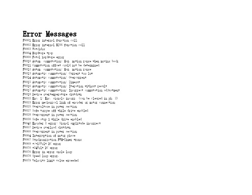
Error MessagesF9001 Error internal function call.F9002 Error internal RTOS function callF9003 WatchdogF9004 Hardware trapF8000 Fatal hardware errorF8010 Autom. commutation: Max. motion range when moving back F8011 Commutation offset could not be determinedF8012 Autom. commutation: Max. motion rangeF8013 Automatic commutation: Current too lowF8014 Automatic commutation: OvercurrentF8015 Automatic commutation: TimeoutF8016 Automatic commutation: Iteration without resultF8017 Automatic commutation: Incorrect commutation adjustment F8018 Device overtemperature shutdownF8022 Enc. 1: Enc. signals incorr. (can be cleared in ph. 2) F8023 Error mechanical link of encoder or motor connectionF8025 Overvoltage in power sectionF8027 Safe torque off while drive enabledF8028 Overcurrent in power sectionF8030 Safe stop 1 while drive enabledF8042 Encoder 2 error: Signal amplitude incorrectF8057 Device overload shutdownF8060 Overcurrent in power sectionF8064 Interruption of motor phaseF8067 Synchronization PWM-Timer wrongF8069 +/-15Volt DC errorF8070 +24Volt DC errorF8076 Error in error angle loopF8078 Speed loop error.F8079 Velocity limit value exceededF8091 Power section defectiveF8100 Error when initializing the parameter handlingF8102 Error when initializing power sectionF8118 Invalid power section/firmware combinationF8120 Invalid control section/firmware combinationF8122 Control section defectiveF8129 Incorrect optional module firmwareF8130 Firmware of option 2 of safety technology defectiveF8133 Error when checking interrupting circuitsF8134 SBS: Fatal errorF8135 SMD: Velocity exceededF8140 Fatal CCD error.F8201 Safety command for basic initialization incorrectF8203 Safety technology configuration parameter invalidF8813 Connection error mains chokeF8830 Power section errorF8838 Overcurrent external braking resistorF7010 Safely-limited increment exceededF7011 Safely-monitored position, exceeded in pos. DirectionF7012 Safely-monitored position, exceeded in neg. DirectionF7013 Safely-limited speed exceededF7020 Safe maximum speed exceededF7021 Safely-limited position exceededF7030 Position window Safe stop 2 exceededF7031 Incorrect direction of motionF7040 Validation error parameterized - effective thresholdF7041 Actual position value validation errorF7042 Validation error of safe operation modeF7043 Error of output stage interlockF7050 Time for stopping process exceeded8.3.15 F7051 Safely-monitored deceleration exceeded (159)8.4 Travel Range Errors (F6xxx) (161)8.4.1 Behavior in the Case of Travel Range Errors (161)8.4.2 F6010 PLC Runtime Error (162)8.4.3 F6024 Maximum braking time exceeded (163)8.4.4 F6028 Position limit value exceeded (overflow) (164)8.4.5 F6029 Positive position limit exceeded (164)8.4.6 F6030 Negative position limit exceeded (165)8.4.7 F6034 Emergency-Stop (166)8.4.8 F6042 Both travel range limit switches activated (167)8.4.9 F6043 Positive travel range limit switch activated (167)8.4.10 F6044 Negative travel range limit switch activated (168)8.4.11 F6140 CCD slave error (emergency halt) (169)8.5 Interface Errors (F4xxx) (169)8.5.1 Behavior in the Case of Interface Errors (169)8.5.2 F4001 Sync telegram failure (170)8.5.3 F4002 RTD telegram failure (171)8.5.4 F4003 Invalid communication phase shutdown (172)8.5.5 F4004 Error during phase progression (172)8.5.6 F4005 Error during phase regression (173)8.5.7 F4006 Phase switching without ready signal (173)8.5.8 F4009 Bus failure (173)8.5.9 F4012 Incorrect I/O length (175)8.5.10 F4016 PLC double real-time channel failure (176)8.5.11 F4017 S-III: Incorrect sequence during phase switch (176)8.5.12 F4034 Emergency-Stop (177)8.5.13 F4140 CCD communication error (178)8.6 Non-Fatal Safety Technology Errors (F3xxx) (178)8.6.1 Behavior in the Case of Non-Fatal Safety Technology Errors (178)8.6.2 F3111 Refer. missing when selecting safety related end pos (179)8.6.3 F3112 Safe reference missing (179)8.6.4 F3115 Brake check time interval exceeded (181)Troubleshooting Guide | Rexroth IndraDrive Electric Drivesand ControlsI Bosch Rexroth AG VII/XXIITable of ContentsPage8.6.5 F3116 Nominal load torque of holding system exceeded (182)8.6.6 F3117 Actual position values validation error (182)8.6.7 F3122 SBS: System error (183)8.6.8 F3123 SBS: Brake check missing (184)8.6.9 F3130 Error when checking input signals (185)8.6.10 F3131 Error when checking acknowledgment signal (185)8.6.11 F3132 Error when checking diagnostic output signal (186)8.6.12 F3133 Error when checking interrupting circuits (187)8.6.13 F3134 Dynamization time interval incorrect (188)8.6.14 F3135 Dynamization pulse width incorrect (189)8.6.15 F3140 Safety parameters validation error (192)8.6.16 F3141 Selection validation error (192)8.6.17 F3142 Activation time of enabling control exceeded (193)8.6.18 F3143 Safety command for clearing errors incorrect (194)8.6.19 F3144 Incorrect safety configuration (195)8.6.20 F3145 Error when unlocking the safety door (196)8.6.21 F3146 System error channel 2 (197)8.6.22 F3147 System error channel 1 (198)8.6.23 F3150 Safety command for system start incorrect (199)8.6.24 F3151 Safety command for system halt incorrect (200)8.6.25 F3152 Incorrect backup of safety technology data (201)8.6.26 F3160 Communication error of safe communication (202)8.7 Non-Fatal Errors (F2xxx) (202)8.7.1 Behavior in the Case of Non-Fatal Errors (202)8.7.2 F2002 Encoder assignment not allowed for synchronization (203)8.7.3 F2003 Motion step skipped (203)8.7.4 F2004 Error in MotionProfile (204)8.7.5 F2005 Cam table invalid (205)8.7.6 F2006 MMC was removed (206)8.7.7 F2007 Switching to non-initialized operation mode (206)8.7.8 F2008 RL The motor type has changed (207)8.7.9 F2009 PL Load parameter default values (208)8.7.10 F2010 Error when initializing digital I/O (-> S-0-0423) (209)8.7.11 F2011 PLC - Error no. 1 (210)8.7.12 F2012 PLC - Error no. 2 (210)8.7.13 F2013 PLC - Error no. 3 (211)8.7.14 F2014 PLC - Error no. 4 (211)8.7.15 F2018 Device overtemperature shutdown (211)8.7.16 F2019 Motor overtemperature shutdown (212)8.7.17 F2021 Motor temperature monitor defective (213)8.7.18 F2022 Device temperature monitor defective (214)8.7.19 F2025 Drive not ready for control (214)8.7.20 F2026 Undervoltage in power section (215)8.7.21 F2027 Excessive oscillation in DC bus (216)8.7.22 F2028 Excessive deviation (216)8.7.23 F2031 Encoder 1 error: Signal amplitude incorrect (217)VIII/XXII Bosch Rexroth AG | Electric Drivesand ControlsRexroth IndraDrive | Troubleshooting GuideTable of ContentsPage8.7.24 F2032 Validation error during commutation fine adjustment (217)8.7.25 F2033 External power supply X10 error (218)8.7.26 F2036 Excessive position feedback difference (219)8.7.27 F2037 Excessive position command difference (220)8.7.28 F2039 Maximum acceleration exceeded (220)8.7.29 F2040 Device overtemperature 2 shutdown (221)8.7.30 F2042 Encoder 2: Encoder signals incorrect (222)8.7.31 F2043 Measuring encoder: Encoder signals incorrect (222)8.7.32 F2044 External power supply X15 error (223)8.7.33 F2048 Low battery voltage (224)8.7.34 F2050 Overflow of target position preset memory (225)8.7.35 F2051 No sequential block in target position preset memory (225)8.7.36 F2053 Incr. encoder emulator: Pulse frequency too high (226)8.7.37 F2054 Incr. encoder emulator: Hardware error (226)8.7.38 F2055 External power supply dig. I/O error (227)8.7.39 F2057 Target position out of travel range (227)8.7.40 F2058 Internal overflow by positioning input (228)8.7.41 F2059 Incorrect command value direction when positioning (229)8.7.42 F2063 Internal overflow master axis generator (230)8.7.43 F2064 Incorrect cmd value direction master axis generator (230)8.7.44 F2067 Synchronization to master communication incorrect (231)8.7.45 F2068 Brake error (231)8.7.46 F2069 Error when releasing the motor holding brake (232)8.7.47 F2074 Actual pos. value 1 outside absolute encoder window (232)8.7.48 F2075 Actual pos. value 2 outside absolute encoder window (233)8.7.49 F2076 Actual pos. value 3 outside absolute encoder window (234)8.7.50 F2077 Current measurement trim wrong (235)8.7.51 F2086 Error supply module (236)8.7.52 F2087 Module group communication error (236)8.7.53 F2100 Incorrect access to command value memory (237)8.7.54 F2101 It was impossible to address MMC (237)8.7.55 F2102 It was impossible to address I2C memory (238)8.7.56 F2103 It was impossible to address EnDat memory (238)8.7.57 F2104 Commutation offset invalid (239)8.7.58 F2105 It was impossible to address Hiperface memory (239)8.7.59 F2110 Error in non-cyclical data communic. of power section (240)8.7.60 F2120 MMC: Defective or missing, replace (240)8.7.61 F2121 MMC: Incorrect data or file, create correctly (241)8.7.62 F2122 MMC: Incorrect IBF file, correct it (241)8.7.63 F2123 Retain data backup impossible (242)8.7.64 F2124 MMC: Saving too slowly, replace (243)8.7.65 F2130 Error comfort control panel (243)8.7.66 F2140 CCD slave error (243)8.7.67 F2150 MLD motion function block error (244)8.7.68 F2174 Loss of motor encoder reference (244)8.7.69 F2175 Loss of optional encoder reference (245)Troubleshooting Guide | Rexroth IndraDrive Electric Drivesand Controls| Bosch Rexroth AG IX/XXIITable of ContentsPage8.7.70 F2176 Loss of measuring encoder reference (246)8.7.71 F2177 Modulo limitation error of motor encoder (246)8.7.72 F2178 Modulo limitation error of optional encoder (247)8.7.73 F2179 Modulo limitation error of measuring encoder (247)8.7.74 F2190 Incorrect Ethernet configuration (248)8.7.75 F2260 Command current limit shutoff (249)8.7.76 F2270 Analog input 1 or 2, wire break (249)8.7.77 F2802 PLL is not synchronized (250)8.7.78 F2814 Undervoltage in mains (250)8.7.79 F2815 Overvoltage in mains (251)8.7.80 F2816 Softstart fault power supply unit (251)8.7.81 F2817 Overvoltage in power section (251)8.7.82 F2818 Phase failure (252)8.7.83 F2819 Mains failure (253)8.7.84 F2820 Braking resistor overload (253)8.7.85 F2821 Error in control of braking resistor (254)8.7.86 F2825 Switch-on threshold braking resistor too low (255)8.7.87 F2833 Ground fault in motor line (255)8.7.88 F2834 Contactor control error (256)8.7.89 F2835 Mains contactor wiring error (256)8.7.90 F2836 DC bus balancing monitor error (257)8.7.91 F2837 Contactor monitoring error (257)8.7.92 F2840 Error supply shutdown (257)8.7.93 F2860 Overcurrent in mains-side power section (258)8.7.94 F2890 Invalid device code (259)8.7.95 F2891 Incorrect interrupt timing (259)8.7.96 F2892 Hardware variant not supported (259)8.8 SERCOS Error Codes / Error Messages of Serial Communication (259)9 Warnings (Exxxx) (263)9.1 Fatal Warnings (E8xxx) (263)9.1.1 Behavior in the Case of Fatal Warnings (263)9.1.2 E8025 Overvoltage in power section (263)9.1.3 E8026 Undervoltage in power section (264)9.1.4 E8027 Safe torque off while drive enabled (265)9.1.5 E8028 Overcurrent in power section (265)9.1.6 E8029 Positive position limit exceeded (266)9.1.7 E8030 Negative position limit exceeded (267)9.1.8 E8034 Emergency-Stop (268)9.1.9 E8040 Torque/force actual value limit active (268)9.1.10 E8041 Current limit active (269)9.1.11 E8042 Both travel range limit switches activated (269)9.1.12 E8043 Positive travel range limit switch activated (270)9.1.13 E8044 Negative travel range limit switch activated (271)9.1.14 E8055 Motor overload, current limit active (271)9.1.15 E8057 Device overload, current limit active (272)X/XXII Bosch Rexroth AG | Electric Drivesand ControlsRexroth IndraDrive | Troubleshooting GuideTable of ContentsPage9.1.16 E8058 Drive system not ready for operation (273)9.1.17 E8260 Torque/force command value limit active (273)9.1.18 E8802 PLL is not synchronized (274)9.1.19 E8814 Undervoltage in mains (275)9.1.20 E8815 Overvoltage in mains (275)9.1.21 E8818 Phase failure (276)9.1.22 E8819 Mains failure (276)9.2 Warnings of Category E4xxx (277)9.2.1 E4001 Double MST failure shutdown (277)9.2.2 E4002 Double MDT failure shutdown (278)9.2.3 E4005 No command value input via master communication (279)9.2.4 E4007 SERCOS III: Consumer connection failed (280)9.2.5 E4008 Invalid addressing command value data container A (280)9.2.6 E4009 Invalid addressing actual value data container A (281)9.2.7 E4010 Slave not scanned or address 0 (281)9.2.8 E4012 Maximum number of CCD slaves exceeded (282)9.2.9 E4013 Incorrect CCD addressing (282)9.2.10 E4014 Incorrect phase switch of CCD slaves (283)9.3 Possible Warnings When Operating Safety Technology (E3xxx) (283)9.3.1 Behavior in Case a Safety Technology Warning Occurs (283)9.3.2 E3100 Error when checking input signals (284)9.3.3 E3101 Error when checking acknowledgment signal (284)9.3.4 E3102 Actual position values validation error (285)9.3.5 E3103 Dynamization failed (285)9.3.6 E3104 Safety parameters validation error (286)9.3.7 E3105 Validation error of safe operation mode (286)9.3.8 E3106 System error safety technology (287)9.3.9 E3107 Safe reference missing (287)9.3.10 E3108 Safely-monitored deceleration exceeded (288)9.3.11 E3110 Time interval of forced dynamization exceeded (289)9.3.12 E3115 Prewarning, end of brake check time interval (289)9.3.13 E3116 Nominal load torque of holding system reached (290)9.4 Non-Fatal Warnings (E2xxx) (290)9.4.1 Behavior in Case a Non-Fatal Warning Occurs (290)9.4.2 E2010 Position control with encoder 2 not possible (291)9.4.3 E2011 PLC - Warning no. 1 (291)9.4.4 E2012 PLC - Warning no. 2 (291)9.4.5 E2013 PLC - Warning no. 3 (292)9.4.6 E2014 PLC - Warning no. 4 (292)9.4.7 E2021 Motor temperature outside of measuring range (292)9.4.8 E2026 Undervoltage in power section (293)9.4.9 E2040 Device overtemperature 2 prewarning (294)9.4.10 E2047 Interpolation velocity = 0 (294)9.4.11 E2048 Interpolation acceleration = 0 (295)9.4.12 E2049 Positioning velocity >= limit value (296)9.4.13 E2050 Device overtemp. Prewarning (297)Troubleshooting Guide | Rexroth IndraDrive Electric Drivesand Controls| Bosch Rexroth AG XI/XXIITable of ContentsPage9.4.14 E2051 Motor overtemp. prewarning (298)9.4.15 E2053 Target position out of travel range (298)9.4.16 E2054 Not homed (300)9.4.17 E2055 Feedrate override S-0-0108 = 0 (300)9.4.18 E2056 Torque limit = 0 (301)9.4.19 E2058 Selected positioning block has not been programmed (302)9.4.20 E2059 Velocity command value limit active (302)9.4.21 E2061 Device overload prewarning (303)9.4.22 E2063 Velocity command value > limit value (304)9.4.23 E2064 Target position out of num. range (304)9.4.24 E2069 Holding brake torque too low (305)9.4.25 E2070 Acceleration limit active (306)9.4.26 E2074 Encoder 1: Encoder signals disturbed (306)9.4.27 E2075 Encoder 2: Encoder signals disturbed (307)9.4.28 E2076 Measuring encoder: Encoder signals disturbed (308)9.4.29 E2077 Absolute encoder monitoring, motor encoder (encoder alarm) (308)9.4.30 E2078 Absolute encoder monitoring, opt. encoder (encoder alarm) (309)9.4.31 E2079 Absolute enc. monitoring, measuring encoder (encoder alarm) (309)9.4.32 E2086 Prewarning supply module overload (310)9.4.33 E2092 Internal synchronization defective (310)9.4.34 E2100 Positioning velocity of master axis generator too high (311)9.4.35 E2101 Acceleration of master axis generator is zero (312)9.4.36 E2140 CCD error at node (312)9.4.37 E2270 Analog input 1 or 2, wire break (312)9.4.38 E2802 HW control of braking resistor (313)9.4.39 E2810 Drive system not ready for operation (314)9.4.40 E2814 Undervoltage in mains (314)9.4.41 E2816 Undervoltage in power section (314)9.4.42 E2818 Phase failure (315)9.4.43 E2819 Mains failure (315)9.4.44 E2820 Braking resistor overload prewarning (316)9.4.45 E2829 Not ready for power on (316)。
critical error message version -回复

critical error message version -回复什么是“critical error message version”?Critical error message version ,即关键错误信息版本,是指在计算机软件或系统中出现的重要错误提示。
这些错误信息通常与系统运行或软件操作相关,当发生关键错误时,会阻碍程序的正常运行,甚至导致系统崩溃。
本文将逐步解析关于“critical error message version”的相关主题,并探讨如何处理和避免这些错误。
第一步:理解关键错误信息版本的作用和意义关键错误信息版本的主要作用是告知用户或软件开发人员系统发生了严重错误。
这种错误可能与文件损坏、硬件故障、网络连接问题或未知错误等有关。
通过错误信息,用户或开发人员可以了解到出现的具体错误类型及其可能的原因,从而更好地找到解决方案。
第二步:探索常见的关键错误信息版本及其意义常见的关键错误信息版本包括但不限于以下几种:1. 蓝屏错误(Blue Screen of Death,简称BSOD):这种错误通常在Windows操作系统中出现。
当系统出现严重问题时,蓝屏错误会显示一条错误代码和错误信息,并导致系统停止运行。
这种错误通常涉及硬件问题,例如内存不足、驱动程序冲突或磁盘错误等。
2. 段错误(segmentation fault):出现在Linux或Unix系统中的关键错误。
它表示正在访问无效内存地址,常常由程序错误或内存泄漏引起。
段错误可能导致程序异常终止或崩溃。
3. 运行时错误(runtime error):这种错误类型通常发生在编译型语言中,如C++或Java。
运行时错误包括空指针引用、除零错误或数组访问越界等。
这些错误会导致程序崩溃或产生不可预测的结果。
4. 数据库错误:当使用数据库进行数据存储和检索时,可能会发生关键错误。
例如,连接超时、无效的SQL查询或数据库损坏等。
3GPP TS 36.331 V13.2.0 (2016-06)

3GPP TS 36.331 V13.2.0 (2016-06)Technical Specification3rd Generation Partnership Project;Technical Specification Group Radio Access Network;Evolved Universal Terrestrial Radio Access (E-UTRA);Radio Resource Control (RRC);Protocol specification(Release 13)The present document has been developed within the 3rd Generation Partnership Project (3GPP TM) and may be further elaborated for the purposes of 3GPP. The present document has not been subject to any approval process by the 3GPP Organizational Partners and shall not be implemented.This Specification is provided for future development work within 3GPP only. The Organizational Partners accept no liability for any use of this Specification. Specifications and reports for implementation of the 3GPP TM system should be obtained via the 3GPP Organizational Partners' Publications Offices.KeywordsUMTS, radio3GPPPostal address3GPP support office address650 Route des Lucioles - Sophia AntipolisValbonne - FRANCETel.: +33 4 92 94 42 00 Fax: +33 4 93 65 47 16InternetCopyright NotificationNo part may be reproduced except as authorized by written permission.The copyright and the foregoing restriction extend to reproduction in all media.© 2016, 3GPP Organizational Partners (ARIB, ATIS, CCSA, ETSI, TSDSI, TTA, TTC).All rights reserved.UMTS™ is a Trade Mark of ETSI registered for the benefit of its members3GPP™ is a Trade Mark of ETSI registered for the benefit of its Members and of the 3GPP Organizational PartnersLTE™ is a Trade Mark of ETSI currently being registered for the benefit of its Members and of the 3GPP Organizational Partners GSM® and the GSM logo are registered and owned by the GSM AssociationBluetooth® is a Trade Mark of the Bluetooth SIG registered for the benefit of its membersContentsForeword (18)1Scope (19)2References (19)3Definitions, symbols and abbreviations (22)3.1Definitions (22)3.2Abbreviations (24)4General (27)4.1Introduction (27)4.2Architecture (28)4.2.1UE states and state transitions including inter RAT (28)4.2.2Signalling radio bearers (29)4.3Services (30)4.3.1Services provided to upper layers (30)4.3.2Services expected from lower layers (30)4.4Functions (30)5Procedures (32)5.1General (32)5.1.1Introduction (32)5.1.2General requirements (32)5.2System information (33)5.2.1Introduction (33)5.2.1.1General (33)5.2.1.2Scheduling (34)5.2.1.2a Scheduling for NB-IoT (34)5.2.1.3System information validity and notification of changes (35)5.2.1.4Indication of ETWS notification (36)5.2.1.5Indication of CMAS notification (37)5.2.1.6Notification of EAB parameters change (37)5.2.1.7Access Barring parameters change in NB-IoT (37)5.2.2System information acquisition (38)5.2.2.1General (38)5.2.2.2Initiation (38)5.2.2.3System information required by the UE (38)5.2.2.4System information acquisition by the UE (39)5.2.2.5Essential system information missing (42)5.2.2.6Actions upon reception of the MasterInformationBlock message (42)5.2.2.7Actions upon reception of the SystemInformationBlockType1 message (42)5.2.2.8Actions upon reception of SystemInformation messages (44)5.2.2.9Actions upon reception of SystemInformationBlockType2 (44)5.2.2.10Actions upon reception of SystemInformationBlockType3 (45)5.2.2.11Actions upon reception of SystemInformationBlockType4 (45)5.2.2.12Actions upon reception of SystemInformationBlockType5 (45)5.2.2.13Actions upon reception of SystemInformationBlockType6 (45)5.2.2.14Actions upon reception of SystemInformationBlockType7 (45)5.2.2.15Actions upon reception of SystemInformationBlockType8 (45)5.2.2.16Actions upon reception of SystemInformationBlockType9 (46)5.2.2.17Actions upon reception of SystemInformationBlockType10 (46)5.2.2.18Actions upon reception of SystemInformationBlockType11 (46)5.2.2.19Actions upon reception of SystemInformationBlockType12 (47)5.2.2.20Actions upon reception of SystemInformationBlockType13 (48)5.2.2.21Actions upon reception of SystemInformationBlockType14 (48)5.2.2.22Actions upon reception of SystemInformationBlockType15 (48)5.2.2.23Actions upon reception of SystemInformationBlockType16 (48)5.2.2.24Actions upon reception of SystemInformationBlockType17 (48)5.2.2.25Actions upon reception of SystemInformationBlockType18 (48)5.2.2.26Actions upon reception of SystemInformationBlockType19 (49)5.2.3Acquisition of an SI message (49)5.2.3a Acquisition of an SI message by BL UE or UE in CE or a NB-IoT UE (50)5.3Connection control (50)5.3.1Introduction (50)5.3.1.1RRC connection control (50)5.3.1.2Security (52)5.3.1.2a RN security (53)5.3.1.3Connected mode mobility (53)5.3.1.4Connection control in NB-IoT (54)5.3.2Paging (55)5.3.2.1General (55)5.3.2.2Initiation (55)5.3.2.3Reception of the Paging message by the UE (55)5.3.3RRC connection establishment (56)5.3.3.1General (56)5.3.3.1a Conditions for establishing RRC Connection for sidelink communication/ discovery (58)5.3.3.2Initiation (59)5.3.3.3Actions related to transmission of RRCConnectionRequest message (63)5.3.3.3a Actions related to transmission of RRCConnectionResumeRequest message (64)5.3.3.4Reception of the RRCConnectionSetup by the UE (64)5.3.3.4a Reception of the RRCConnectionResume by the UE (66)5.3.3.5Cell re-selection while T300, T302, T303, T305, T306, or T308 is running (68)5.3.3.6T300 expiry (68)5.3.3.7T302, T303, T305, T306, or T308 expiry or stop (69)5.3.3.8Reception of the RRCConnectionReject by the UE (70)5.3.3.9Abortion of RRC connection establishment (71)5.3.3.10Handling of SSAC related parameters (71)5.3.3.11Access barring check (72)5.3.3.12EAB check (73)5.3.3.13Access barring check for ACDC (73)5.3.3.14Access Barring check for NB-IoT (74)5.3.4Initial security activation (75)5.3.4.1General (75)5.3.4.2Initiation (76)5.3.4.3Reception of the SecurityModeCommand by the UE (76)5.3.5RRC connection reconfiguration (77)5.3.5.1General (77)5.3.5.2Initiation (77)5.3.5.3Reception of an RRCConnectionReconfiguration not including the mobilityControlInfo by theUE (77)5.3.5.4Reception of an RRCConnectionReconfiguration including the mobilityControlInfo by the UE(handover) (79)5.3.5.5Reconfiguration failure (83)5.3.5.6T304 expiry (handover failure) (83)5.3.5.7Void (84)5.3.5.7a T307 expiry (SCG change failure) (84)5.3.5.8Radio Configuration involving full configuration option (84)5.3.6Counter check (86)5.3.6.1General (86)5.3.6.2Initiation (86)5.3.6.3Reception of the CounterCheck message by the UE (86)5.3.7RRC connection re-establishment (87)5.3.7.1General (87)5.3.7.2Initiation (87)5.3.7.3Actions following cell selection while T311 is running (88)5.3.7.4Actions related to transmission of RRCConnectionReestablishmentRequest message (89)5.3.7.5Reception of the RRCConnectionReestablishment by the UE (89)5.3.7.6T311 expiry (91)5.3.7.7T301 expiry or selected cell no longer suitable (91)5.3.7.8Reception of RRCConnectionReestablishmentReject by the UE (91)5.3.8RRC connection release (92)5.3.8.1General (92)5.3.8.2Initiation (92)5.3.8.3Reception of the RRCConnectionRelease by the UE (92)5.3.8.4T320 expiry (93)5.3.9RRC connection release requested by upper layers (93)5.3.9.1General (93)5.3.9.2Initiation (93)5.3.10Radio resource configuration (93)5.3.10.0General (93)5.3.10.1SRB addition/ modification (94)5.3.10.2DRB release (95)5.3.10.3DRB addition/ modification (95)5.3.10.3a1DC specific DRB addition or reconfiguration (96)5.3.10.3a2LWA specific DRB addition or reconfiguration (98)5.3.10.3a3LWIP specific DRB addition or reconfiguration (98)5.3.10.3a SCell release (99)5.3.10.3b SCell addition/ modification (99)5.3.10.3c PSCell addition or modification (99)5.3.10.4MAC main reconfiguration (99)5.3.10.5Semi-persistent scheduling reconfiguration (100)5.3.10.6Physical channel reconfiguration (100)5.3.10.7Radio Link Failure Timers and Constants reconfiguration (101)5.3.10.8Time domain measurement resource restriction for serving cell (101)5.3.10.9Other configuration (102)5.3.10.10SCG reconfiguration (103)5.3.10.11SCG dedicated resource configuration (104)5.3.10.12Reconfiguration SCG or split DRB by drb-ToAddModList (105)5.3.10.13Neighbour cell information reconfiguration (105)5.3.10.14Void (105)5.3.10.15Sidelink dedicated configuration (105)5.3.10.16T370 expiry (106)5.3.11Radio link failure related actions (107)5.3.11.1Detection of physical layer problems in RRC_CONNECTED (107)5.3.11.2Recovery of physical layer problems (107)5.3.11.3Detection of radio link failure (107)5.3.12UE actions upon leaving RRC_CONNECTED (109)5.3.13UE actions upon PUCCH/ SRS release request (110)5.3.14Proximity indication (110)5.3.14.1General (110)5.3.14.2Initiation (111)5.3.14.3Actions related to transmission of ProximityIndication message (111)5.3.15Void (111)5.4Inter-RAT mobility (111)5.4.1Introduction (111)5.4.2Handover to E-UTRA (112)5.4.2.1General (112)5.4.2.2Initiation (112)5.4.2.3Reception of the RRCConnectionReconfiguration by the UE (112)5.4.2.4Reconfiguration failure (114)5.4.2.5T304 expiry (handover to E-UTRA failure) (114)5.4.3Mobility from E-UTRA (114)5.4.3.1General (114)5.4.3.2Initiation (115)5.4.3.3Reception of the MobilityFromEUTRACommand by the UE (115)5.4.3.4Successful completion of the mobility from E-UTRA (116)5.4.3.5Mobility from E-UTRA failure (117)5.4.4Handover from E-UTRA preparation request (CDMA2000) (117)5.4.4.1General (117)5.4.4.2Initiation (118)5.4.4.3Reception of the HandoverFromEUTRAPreparationRequest by the UE (118)5.4.5UL handover preparation transfer (CDMA2000) (118)5.4.5.1General (118)5.4.5.2Initiation (118)5.4.5.3Actions related to transmission of the ULHandoverPreparationTransfer message (119)5.4.5.4Failure to deliver the ULHandoverPreparationTransfer message (119)5.4.6Inter-RAT cell change order to E-UTRAN (119)5.4.6.1General (119)5.4.6.2Initiation (119)5.4.6.3UE fails to complete an inter-RAT cell change order (119)5.5Measurements (120)5.5.1Introduction (120)5.5.2Measurement configuration (121)5.5.2.1General (121)5.5.2.2Measurement identity removal (122)5.5.2.2a Measurement identity autonomous removal (122)5.5.2.3Measurement identity addition/ modification (123)5.5.2.4Measurement object removal (124)5.5.2.5Measurement object addition/ modification (124)5.5.2.6Reporting configuration removal (126)5.5.2.7Reporting configuration addition/ modification (127)5.5.2.8Quantity configuration (127)5.5.2.9Measurement gap configuration (127)5.5.2.10Discovery signals measurement timing configuration (128)5.5.2.11RSSI measurement timing configuration (128)5.5.3Performing measurements (128)5.5.3.1General (128)5.5.3.2Layer 3 filtering (131)5.5.4Measurement report triggering (131)5.5.4.1General (131)5.5.4.2Event A1 (Serving becomes better than threshold) (135)5.5.4.3Event A2 (Serving becomes worse than threshold) (136)5.5.4.4Event A3 (Neighbour becomes offset better than PCell/ PSCell) (136)5.5.4.5Event A4 (Neighbour becomes better than threshold) (137)5.5.4.6Event A5 (PCell/ PSCell becomes worse than threshold1 and neighbour becomes better thanthreshold2) (138)5.5.4.6a Event A6 (Neighbour becomes offset better than SCell) (139)5.5.4.7Event B1 (Inter RAT neighbour becomes better than threshold) (139)5.5.4.8Event B2 (PCell becomes worse than threshold1 and inter RAT neighbour becomes better thanthreshold2) (140)5.5.4.9Event C1 (CSI-RS resource becomes better than threshold) (141)5.5.4.10Event C2 (CSI-RS resource becomes offset better than reference CSI-RS resource) (141)5.5.4.11Event W1 (WLAN becomes better than a threshold) (142)5.5.4.12Event W2 (All WLAN inside WLAN mobility set becomes worse than threshold1 and a WLANoutside WLAN mobility set becomes better than threshold2) (142)5.5.4.13Event W3 (All WLAN inside WLAN mobility set becomes worse than a threshold) (143)5.5.5Measurement reporting (144)5.5.6Measurement related actions (148)5.5.6.1Actions upon handover and re-establishment (148)5.5.6.2Speed dependant scaling of measurement related parameters (149)5.5.7Inter-frequency RSTD measurement indication (149)5.5.7.1General (149)5.5.7.2Initiation (150)5.5.7.3Actions related to transmission of InterFreqRSTDMeasurementIndication message (150)5.6Other (150)5.6.0General (150)5.6.1DL information transfer (151)5.6.1.1General (151)5.6.1.2Initiation (151)5.6.1.3Reception of the DLInformationTransfer by the UE (151)5.6.2UL information transfer (151)5.6.2.1General (151)5.6.2.2Initiation (151)5.6.2.3Actions related to transmission of ULInformationTransfer message (152)5.6.2.4Failure to deliver ULInformationTransfer message (152)5.6.3UE capability transfer (152)5.6.3.1General (152)5.6.3.2Initiation (153)5.6.3.3Reception of the UECapabilityEnquiry by the UE (153)5.6.4CSFB to 1x Parameter transfer (157)5.6.4.1General (157)5.6.4.2Initiation (157)5.6.4.3Actions related to transmission of CSFBParametersRequestCDMA2000 message (157)5.6.4.4Reception of the CSFBParametersResponseCDMA2000 message (157)5.6.5UE Information (158)5.6.5.1General (158)5.6.5.2Initiation (158)5.6.5.3Reception of the UEInformationRequest message (158)5.6.6 Logged Measurement Configuration (159)5.6.6.1General (159)5.6.6.2Initiation (160)5.6.6.3Reception of the LoggedMeasurementConfiguration by the UE (160)5.6.6.4T330 expiry (160)5.6.7 Release of Logged Measurement Configuration (160)5.6.7.1General (160)5.6.7.2Initiation (160)5.6.8 Measurements logging (161)5.6.8.1General (161)5.6.8.2Initiation (161)5.6.9In-device coexistence indication (163)5.6.9.1General (163)5.6.9.2Initiation (164)5.6.9.3Actions related to transmission of InDeviceCoexIndication message (164)5.6.10UE Assistance Information (165)5.6.10.1General (165)5.6.10.2Initiation (166)5.6.10.3Actions related to transmission of UEAssistanceInformation message (166)5.6.11 Mobility history information (166)5.6.11.1General (166)5.6.11.2Initiation (166)5.6.12RAN-assisted WLAN interworking (167)5.6.12.1General (167)5.6.12.2Dedicated WLAN offload configuration (167)5.6.12.3WLAN offload RAN evaluation (167)5.6.12.4T350 expiry or stop (167)5.6.12.5Cell selection/ re-selection while T350 is running (168)5.6.13SCG failure information (168)5.6.13.1General (168)5.6.13.2Initiation (168)5.6.13.3Actions related to transmission of SCGFailureInformation message (168)5.6.14LTE-WLAN Aggregation (169)5.6.14.1Introduction (169)5.6.14.2Reception of LWA configuration (169)5.6.14.3Release of LWA configuration (170)5.6.15WLAN connection management (170)5.6.15.1Introduction (170)5.6.15.2WLAN connection status reporting (170)5.6.15.2.1General (170)5.6.15.2.2Initiation (171)5.6.15.2.3Actions related to transmission of WLANConnectionStatusReport message (171)5.6.15.3T351 Expiry (WLAN connection attempt timeout) (171)5.6.15.4WLAN status monitoring (171)5.6.16RAN controlled LTE-WLAN interworking (172)5.6.16.1General (172)5.6.16.2WLAN traffic steering command (172)5.6.17LTE-WLAN aggregation with IPsec tunnel (173)5.6.17.1General (173)5.7Generic error handling (174)5.7.1General (174)5.7.2ASN.1 violation or encoding error (174)5.7.3Field set to a not comprehended value (174)5.7.4Mandatory field missing (174)5.7.5Not comprehended field (176)5.8MBMS (176)5.8.1Introduction (176)5.8.1.1General (176)5.8.1.2Scheduling (176)5.8.1.3MCCH information validity and notification of changes (176)5.8.2MCCH information acquisition (178)5.8.2.1General (178)5.8.2.2Initiation (178)5.8.2.3MCCH information acquisition by the UE (178)5.8.2.4Actions upon reception of the MBSFNAreaConfiguration message (178)5.8.2.5Actions upon reception of the MBMSCountingRequest message (179)5.8.3MBMS PTM radio bearer configuration (179)5.8.3.1General (179)5.8.3.2Initiation (179)5.8.3.3MRB establishment (179)5.8.3.4MRB release (179)5.8.4MBMS Counting Procedure (179)5.8.4.1General (179)5.8.4.2Initiation (180)5.8.4.3Reception of the MBMSCountingRequest message by the UE (180)5.8.5MBMS interest indication (181)5.8.5.1General (181)5.8.5.2Initiation (181)5.8.5.3Determine MBMS frequencies of interest (182)5.8.5.4Actions related to transmission of MBMSInterestIndication message (183)5.8a SC-PTM (183)5.8a.1Introduction (183)5.8a.1.1General (183)5.8a.1.2SC-MCCH scheduling (183)5.8a.1.3SC-MCCH information validity and notification of changes (183)5.8a.1.4Procedures (184)5.8a.2SC-MCCH information acquisition (184)5.8a.2.1General (184)5.8a.2.2Initiation (184)5.8a.2.3SC-MCCH information acquisition by the UE (184)5.8a.2.4Actions upon reception of the SCPTMConfiguration message (185)5.8a.3SC-PTM radio bearer configuration (185)5.8a.3.1General (185)5.8a.3.2Initiation (185)5.8a.3.3SC-MRB establishment (185)5.8a.3.4SC-MRB release (185)5.9RN procedures (186)5.9.1RN reconfiguration (186)5.9.1.1General (186)5.9.1.2Initiation (186)5.9.1.3Reception of the RNReconfiguration by the RN (186)5.10Sidelink (186)5.10.1Introduction (186)5.10.1a Conditions for sidelink communication operation (187)5.10.2Sidelink UE information (188)5.10.2.1General (188)5.10.2.2Initiation (189)5.10.2.3Actions related to transmission of SidelinkUEInformation message (193)5.10.3Sidelink communication monitoring (195)5.10.6Sidelink discovery announcement (198)5.10.6a Sidelink discovery announcement pool selection (201)5.10.6b Sidelink discovery announcement reference carrier selection (201)5.10.7Sidelink synchronisation information transmission (202)5.10.7.1General (202)5.10.7.2Initiation (203)5.10.7.3Transmission of SLSS (204)5.10.7.4Transmission of MasterInformationBlock-SL message (205)5.10.7.5Void (206)5.10.8Sidelink synchronisation reference (206)5.10.8.1General (206)5.10.8.2Selection and reselection of synchronisation reference UE (SyncRef UE) (206)5.10.9Sidelink common control information (207)5.10.9.1General (207)5.10.9.2Actions related to reception of MasterInformationBlock-SL message (207)5.10.10Sidelink relay UE operation (207)5.10.10.1General (207)5.10.10.2AS-conditions for relay related sidelink communication transmission by sidelink relay UE (207)5.10.10.3AS-conditions for relay PS related sidelink discovery transmission by sidelink relay UE (208)5.10.10.4Sidelink relay UE threshold conditions (208)5.10.11Sidelink remote UE operation (208)5.10.11.1General (208)5.10.11.2AS-conditions for relay related sidelink communication transmission by sidelink remote UE (208)5.10.11.3AS-conditions for relay PS related sidelink discovery transmission by sidelink remote UE (209)5.10.11.4Selection and reselection of sidelink relay UE (209)5.10.11.5Sidelink remote UE threshold conditions (210)6Protocol data units, formats and parameters (tabular & ASN.1) (210)6.1General (210)6.2RRC messages (212)6.2.1General message structure (212)–EUTRA-RRC-Definitions (212)–BCCH-BCH-Message (212)–BCCH-DL-SCH-Message (212)–BCCH-DL-SCH-Message-BR (213)–MCCH-Message (213)–PCCH-Message (213)–DL-CCCH-Message (214)–DL-DCCH-Message (214)–UL-CCCH-Message (214)–UL-DCCH-Message (215)–SC-MCCH-Message (215)6.2.2Message definitions (216)–CounterCheck (216)–CounterCheckResponse (217)–CSFBParametersRequestCDMA2000 (217)–CSFBParametersResponseCDMA2000 (218)–DLInformationTransfer (218)–HandoverFromEUTRAPreparationRequest (CDMA2000) (219)–InDeviceCoexIndication (220)–InterFreqRSTDMeasurementIndication (222)–LoggedMeasurementConfiguration (223)–MasterInformationBlock (225)–MBMSCountingRequest (226)–MBMSCountingResponse (226)–MBMSInterestIndication (227)–MBSFNAreaConfiguration (228)–MeasurementReport (228)–MobilityFromEUTRACommand (229)–Paging (232)–ProximityIndication (233)–RNReconfiguration (234)–RNReconfigurationComplete (234)–RRCConnectionReconfiguration (235)–RRCConnectionReconfigurationComplete (240)–RRCConnectionReestablishment (241)–RRCConnectionReestablishmentComplete (241)–RRCConnectionReestablishmentReject (242)–RRCConnectionReestablishmentRequest (243)–RRCConnectionReject (243)–RRCConnectionRelease (244)–RRCConnectionResume (248)–RRCConnectionResumeComplete (249)–RRCConnectionResumeRequest (250)–RRCConnectionRequest (250)–RRCConnectionSetup (251)–RRCConnectionSetupComplete (252)–SCGFailureInformation (253)–SCPTMConfiguration (254)–SecurityModeCommand (255)–SecurityModeComplete (255)–SecurityModeFailure (256)–SidelinkUEInformation (256)–SystemInformation (258)–SystemInformationBlockType1 (259)–UEAssistanceInformation (264)–UECapabilityEnquiry (265)–UECapabilityInformation (266)–UEInformationRequest (267)–UEInformationResponse (267)–ULHandoverPreparationTransfer (CDMA2000) (273)–ULInformationTransfer (274)–WLANConnectionStatusReport (274)6.3RRC information elements (275)6.3.1System information blocks (275)–SystemInformationBlockType2 (275)–SystemInformationBlockType3 (279)–SystemInformationBlockType4 (282)–SystemInformationBlockType5 (283)–SystemInformationBlockType6 (287)–SystemInformationBlockType7 (289)–SystemInformationBlockType8 (290)–SystemInformationBlockType9 (295)–SystemInformationBlockType10 (295)–SystemInformationBlockType11 (296)–SystemInformationBlockType12 (297)–SystemInformationBlockType13 (297)–SystemInformationBlockType14 (298)–SystemInformationBlockType15 (298)–SystemInformationBlockType16 (299)–SystemInformationBlockType17 (300)–SystemInformationBlockType18 (301)–SystemInformationBlockType19 (301)–SystemInformationBlockType20 (304)6.3.2Radio resource control information elements (304)–AntennaInfo (304)–AntennaInfoUL (306)–CQI-ReportConfig (307)–CQI-ReportPeriodicProcExtId (314)–CrossCarrierSchedulingConfig (314)–CSI-IM-Config (315)–CSI-IM-ConfigId (315)–CSI-RS-Config (317)–CSI-RS-ConfigEMIMO (318)–CSI-RS-ConfigNZP (319)–CSI-RS-ConfigNZPId (320)–CSI-RS-ConfigZP (321)–CSI-RS-ConfigZPId (321)–DMRS-Config (321)–DRB-Identity (322)–EPDCCH-Config (322)–EIMTA-MainConfig (324)–LogicalChannelConfig (325)–LWA-Configuration (326)–LWIP-Configuration (326)–RCLWI-Configuration (327)–MAC-MainConfig (327)–P-C-AndCBSR (332)–PDCCH-ConfigSCell (333)–PDCP-Config (334)–PDSCH-Config (337)–PDSCH-RE-MappingQCL-ConfigId (339)–PHICH-Config (339)–PhysicalConfigDedicated (339)–P-Max (344)–PRACH-Config (344)–PresenceAntennaPort1 (346)–PUCCH-Config (347)–PUSCH-Config (351)–RACH-ConfigCommon (355)–RACH-ConfigDedicated (357)–RadioResourceConfigCommon (358)–RadioResourceConfigDedicated (362)–RLC-Config (367)–RLF-TimersAndConstants (369)–RN-SubframeConfig (370)–SchedulingRequestConfig (371)–SoundingRS-UL-Config (372)–SPS-Config (375)–TDD-Config (376)–TimeAlignmentTimer (377)–TPC-PDCCH-Config (377)–TunnelConfigLWIP (378)–UplinkPowerControl (379)–WLAN-Id-List (382)–WLAN-MobilityConfig (382)6.3.3Security control information elements (382)–NextHopChainingCount (382)–SecurityAlgorithmConfig (383)–ShortMAC-I (383)6.3.4Mobility control information elements (383)–AdditionalSpectrumEmission (383)–ARFCN-ValueCDMA2000 (383)–ARFCN-ValueEUTRA (384)–ARFCN-ValueGERAN (384)–ARFCN-ValueUTRA (384)–BandclassCDMA2000 (384)–BandIndicatorGERAN (385)–CarrierFreqCDMA2000 (385)–CarrierFreqGERAN (385)–CellIndexList (387)–CellReselectionPriority (387)–CellSelectionInfoCE (387)–CellReselectionSubPriority (388)–CSFB-RegistrationParam1XRTT (388)–CellGlobalIdEUTRA (389)–CellGlobalIdUTRA (389)–CellGlobalIdGERAN (390)–CellGlobalIdCDMA2000 (390)–CellSelectionInfoNFreq (391)–CSG-Identity (391)–FreqBandIndicator (391)–MobilityControlInfo (391)–MobilityParametersCDMA2000 (1xRTT) (393)–MobilityStateParameters (394)–MultiBandInfoList (394)–NS-PmaxList (394)–PhysCellId (395)–PhysCellIdRange (395)–PhysCellIdRangeUTRA-FDDList (395)–PhysCellIdCDMA2000 (396)–PhysCellIdGERAN (396)–PhysCellIdUTRA-FDD (396)–PhysCellIdUTRA-TDD (396)–PLMN-Identity (397)–PLMN-IdentityList3 (397)–PreRegistrationInfoHRPD (397)–Q-QualMin (398)–Q-RxLevMin (398)–Q-OffsetRange (398)–Q-OffsetRangeInterRAT (399)–ReselectionThreshold (399)–ReselectionThresholdQ (399)–SCellIndex (399)–ServCellIndex (400)–SpeedStateScaleFactors (400)–SystemInfoListGERAN (400)–SystemTimeInfoCDMA2000 (401)–TrackingAreaCode (401)–T-Reselection (402)–T-ReselectionEUTRA-CE (402)6.3.5Measurement information elements (402)–AllowedMeasBandwidth (402)–CSI-RSRP-Range (402)–Hysteresis (402)–LocationInfo (403)–MBSFN-RSRQ-Range (403)–MeasConfig (404)–MeasDS-Config (405)–MeasGapConfig (406)–MeasId (407)–MeasIdToAddModList (407)–MeasObjectCDMA2000 (408)–MeasObjectEUTRA (408)–MeasObjectGERAN (412)–MeasObjectId (412)–MeasObjectToAddModList (412)–MeasObjectUTRA (413)–ReportConfigEUTRA (422)–ReportConfigId (425)–ReportConfigInterRAT (425)–ReportConfigToAddModList (428)–ReportInterval (429)–RSRP-Range (429)–RSRQ-Range (430)–RSRQ-Type (430)–RS-SINR-Range (430)–RSSI-Range-r13 (431)–TimeToTrigger (431)–UL-DelayConfig (431)–WLAN-CarrierInfo (431)–WLAN-RSSI-Range (432)–WLAN-Status (432)6.3.6Other information elements (433)–AbsoluteTimeInfo (433)–AreaConfiguration (433)–C-RNTI (433)–DedicatedInfoCDMA2000 (434)–DedicatedInfoNAS (434)–FilterCoefficient (434)–LoggingDuration (434)–LoggingInterval (435)–MeasSubframePattern (435)–MMEC (435)–NeighCellConfig (435)–OtherConfig (436)–RAND-CDMA2000 (1xRTT) (437)–RAT-Type (437)–ResumeIdentity (437)–RRC-TransactionIdentifier (438)–S-TMSI (438)–TraceReference (438)–UE-CapabilityRAT-ContainerList (438)–UE-EUTRA-Capability (439)–UE-RadioPagingInfo (469)–UE-TimersAndConstants (469)–VisitedCellInfoList (470)–WLAN-OffloadConfig (470)6.3.7MBMS information elements (472)–MBMS-NotificationConfig (472)–MBMS-ServiceList (473)–MBSFN-AreaId (473)–MBSFN-AreaInfoList (473)–MBSFN-SubframeConfig (474)–PMCH-InfoList (475)6.3.7a SC-PTM information elements (476)–SC-MTCH-InfoList (476)–SCPTM-NeighbourCellList (478)6.3.8Sidelink information elements (478)–SL-CommConfig (478)–SL-CommResourcePool (479)–SL-CP-Len (480)–SL-DiscConfig (481)–SL-DiscResourcePool (483)–SL-DiscTxPowerInfo (485)–SL-GapConfig (485)。
- 1、下载文档前请自行甄别文档内容的完整性,平台不提供额外的编辑、内容补充、找答案等附加服务。
- 2、"仅部分预览"的文档,不可在线预览部分如存在完整性等问题,可反馈申请退款(可完整预览的文档不适用该条件!)。
- 3、如文档侵犯您的权益,请联系客服反馈,我们会尽快为您处理(人工客服工作时间:9:00-18:30)。
Error Code
Event ID
Type
0x80010000 80010002-0701ffff Warning
Action
1. If the machine has been recently installed, moved, or serviced, ensure the system battery is properly seated, and the system battery polarity is correct.
1. Remove all expansion cards from the blade server (seeRemoving an I/O expansion card).
2. Remove all storage drives from the blade server (seeRemoving a hot-swap storage drive).
Follow the sugge are listed in the Action column until the problem is solved.
See Parts listing to determine which components are consumable, structural, or CRU parts.
“”
3 “” 2 413“” 2 1 5
“” 21P961P9610 3 2 1 4 3 2 271 1
“” 3 21“”“”
P17-3D C B A3P682 1 2 1
“” C
BP17-23 1 A 3 D C“” B A2P16“8”---“-” 2 1 10
C
B A 3 2“” 1 “”
3 2 “”1 …… ………………17
Error Code = IMM events displayed by AMM (for example, Service Advisor, AMM web interface)
Event ID = IMM events displayed by DSA diagnostic program (for example, in the Chassis Event Log section)
See Parts listing to determine which components are consumable, structural, or CRU parts.
If an action step is preceded by "(Trained technician only)," that step must be performed only by a trained technician.
1 320082 1 3
3 2 1 “” 23WOR1D
21
23WOR1DWO---RDWwOorRdDw1ordword
Error Message
System board (CMOS battery) voltage under warning threshold. with chassis Reading: X, Threshold: Y
3. If the error still occurs, replace the system-board assembly (see Removing the system-board assemblyand Installing the system-board assembly).
Follow the suggested actions in the order in which they are listed in the Action column until the problem is solved.
IMM error messages
Use this information to resolve IMM error messages.
The following table lists IMM error messages and suggested actions to correct the detected problems. Deassertive events not listed in this table are informational only. Notes:
2. Replace the system battery (see Removing the batteryand Installing the battery).
0x80010200 80010202-0701ffff Error
System board (CMOS battery) voltage under critical threshold. Reading:X, Threshold: Y
1. Remove all expansion cards from the blade server (seeRemoving an I/O expansion card).
2. Remove all storage drives from the blade server (seeRemoving a hot-swap storage drive).
Error Code
Event ID
Type
0x80010200 80010202-0701ffff Error
Error Message
Action
System board (SysBrd 5V) voltage under critical threshold. with chassis Reading: X, Threshold: Y