PMWD20XN,118;中文规格书,Datasheet资料
PMEG4020ER,115;中文规格书,Datasheet资料
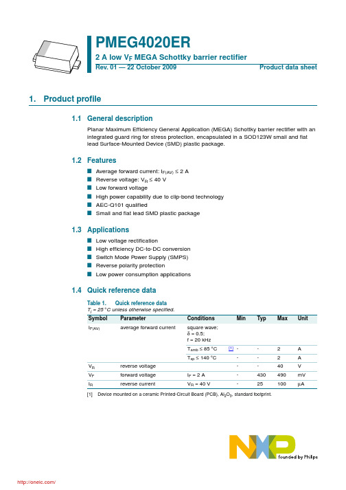
PMEG4020ER_1
Product data sheet
/
Rev. 01 — 22 October 2009
© NXP B.V. 2009. All rights reserved.
4 of 13
NXP Semiconductors
PMEG4020ER
2 A low VF MEGA Schottky barrier rectifier
7. Characteristics
Table 7. Characteristics Tj = 25 °C unless otherwise specified.
Symbol Parameter
Conditions
VF
forward voltage
IF = 0.1 A
IF = 1 A
IF = 2 A
IR
Version SOD123W
4. Marking
Table 4. Marking codes Type number PMEG4020ER
Marking code BE
5. Limiting values
Table 5. Limiting values In accordance with the Absolute Maximum Rating System (IEC 60134).
2 A low VF MEGA Schottky barrier rectifier
2. Pinning information
Table 2. Pin 1 2
Pinning Description cathode anode
[1] The marking bar indicates the cathode.
PN20系列中文说明书
可通过电控方式锁定设备,以避免意外调整设定参数。 请按住两个按钮,直至显示 。 若要解锁: 请按住两个按钮,直至显示 。 设备出厂交货时处于解锁状态。 若设备处于锁定状态,则尝试更改参数值时, 显示片刻。
9
安装和设定/操作
安装、配线和设定完成后,请检查设备是否正常运行。 操作时显示的故障:
过载(高于传感器的测量范围)。 欠载(低于传感器的测量范围)。 闪烁:开关输出1短路*。 闪烁:开关输出2短路*。 闪烁:两个开关输出都短路*。 *只要短路持续发生,就会始终关闭相关的输出功能。 即使已禁用显示器,仍会显示此故障。
2
按住“设定”按钮不放。 当前参数值将闪烁 5 s,然后值会增大*(轻按以递增模式或按 住不放以滚动模式)。
CN
3
���������� ���
轻按“模式/选定”按钮(= 确认)。 将再次显示参数,且设定参数值将生效。
完成编程: 稍候 15 s 或按住“模式/选定”按钮,直至再 4 次指示当前测量值。 *减小值: 将显示的参数值更改为最大设定值。 然后以最低设定值再次执行该操作过程。 设定参数 SPx、rPx、ASP、AEP 的值前应选择显示单位 (Uni)。 这样可避免转换单位时内部 发生舍入误差,以准确设定值。 出厂设定:bar/mbar。 如在设定程序中 15 s 内未按下任何按钮,则设备将返回“运行”模式,其值保持不变。 更改更多参数: 从步骤 1 开始再次执行。
PN2021
PN2022
PN2023
PN2024
5
订购号 PN2026 bar PSI kPa mbar PSI kPa inH2O mbar PSI kPa inH2O inHg mbar PSI kPa inH2O
331KD20NX中文资料

182KD20NX*thru180LD20NX*11 to 1000 VoltsVaristor7.0 to 695.0 JouleFeatures• Radial-Lead Varistor• Designed to be Operated Continuously Across AC Power Lines • No Derating Up to 85к Ambient• Available in Tape and Reel or Bulk PackMaximum Ratings• Operating Ambient Temperature Range: -55к to +85к• Storage Temperature Range: -55к to +125к• Temperature Coefficient (өV) of Clamping Voltage (V C ) at Specified Test Current:<0.05%/к•Varistor voltage temperature coefficient:CURRENT, ENERGY AND POWER DERATING CURVE-551606080100120204060AMBIENT TEMPERATURE (°C)PERCENT OF RATED VALUE14080100120•UL Recognized File # E306895(UL1449) and E306942(UL1414)Note : 'X' can be S, C, I or Y .*'S' denotes straight lead'C' denotes out crimped lead 'I' denotes inner crimped lead 'Y' denotes kink leadomp onents 20736 Marilla Street Chatsworth! "# $ %! "#TMMicro Commercial Components160x(100/ć)Electrical Characteristics @ 25O C Unless Otherwise Noted*680K-180L Max. Clamping Voltage testing current 20AMicro Commercial Components(V)(V)(J)(V)(V)182KD20N X 100014656951800(1620-1980)2970112KD20N X 6808954961100(990-1210)1815102KD20N X 6258254481000(900-1100)1650911KD20N X 550745408910(819-1001)1500821KD20N X 510670376820(738-902)1355781KD20N X 485640368780(702-858)1290751KD20N X 460615360750(675-825)1240681KD20N X 420560344680(612-748)1120621KD20N X 385505328620(558-682)1025561KD20N X 350460312560(504-616)920511KD20N X 320418296510(459-561)842471KD20N X 300385280470(423-517)775431KD20N X 275350264430(387-473)710391KD20N X 250320240390(351-429)650361KD20N X 230300208360(324-396)595331KD20N X 210275184330(297-363)550301KD20N X 195250168300(270-330)505271KD20N X 175225158270(243-297)455241KD20N X 150200134240(216-264)395221KD20N X 140180124220(198-242)360201KD20N X 130170114200(185-225)330181KD20N X 115150104180(162-198)300151KD20N X 9512588150(135-165)250121KD20N X 7510064120(108-132)200101KD20N X 608556100(90-110)165820KD20N X 50654482(74-90)135680KD20N X 40562468(61-75)*135560KD20N X 35452056(50-62)*110470KD20N X 30381747(42-52)*93390KD20N X 25311439(35-43)*77330KD20N X 20261233(30-36)*65270KD20N X 17221027(24-30)*53220KD20N X 1418822(20-24)*43180LD20N X1014718(15-21)*36V 100A (A)200010000.2650040001Rated WattageVaristor VoltageMaximum Clamping Voltage ACrms DC 10/1000us1 time2 times(W)V1mA Part NumberMaximum AllowableVoltageMaximum EnergyWithstanding SurgeCurrent570504030AV-I Curve (820K to 561K)V10090806020069560302040030020010070AV-I Curve (330K to 680K)VMicro Commercial Components2000400030005000AV-I Curve (621K to 182K)V 3204030024530502004005001101001000V-I Surge Life Time Ratings (330K to 680K)AµsImpulse Current – Amperes Impulse Width – Micro seconds 3000100003204030024530502004005001101001000V-I Surge Life Time Ratings (820K to 182K)AµsImpulse Current – Amperes Impulse Width – Micro seconds300010000Micro Commercial ComponentsMicro Commercial Components Note 2.T Thickness (max.)Unit:mmPart Code D05D07D10D14D20 182K12.612.813.5112K10.510.711.2102K9.910.110.7911K9.49.610.1821K8.38.89.09.5781K8.18.68.89.3751K7.97.98.48.69.1681K7.57.58.08.28.7621K7.27.27.67.88.3561K 6.9 6.97.37.58.0511K 6.6 6.67.07.27.7471K 6.4 6.4 6.87.07.5431K 6.1 6.1 6.5 6.77.2391K 5.3 5.3 5.7 5.9 6.4361K 5.1 5.1 5.5 5.7 6.2331K 4.9 4.9 5.3 5.5 6.0301K 4.8 4.8 5.2 5.4 5.9271K 4.6 4.6 5.0 5.2 5.7241K 4.4 4.4 4.8 5.0 5.5221K 4.3 4.3 4.7 4.9 5.4201K 4.2 4.2 4.6 4.8 5.3181K 4.1 4.1 4.5 4.7 5.2151K 4.5 4.5 4.9 5.1 5.6121K 4.1 4.1 4.5 4.6 5.3101K 3.9 3.9 4.4 4.5 5.1820K 3.8 3.8 4.3 4.4 4.9680K 5.5 5.5 6.0 6.1 6.1560K 5.0 5.0 5.5 5.6 5.6470K 5.0 5.0 5.5 5.6 5.6390K 4.7 4.7 5.1 5.2 5.4330K 4.7 4.7 5.1 5.2 5.4270K 4.7 4.7 5.1 5.2 5.4220K 4.5 4.5 4.9 5.0 5.3180L 4.5 4.5 4.9 5.0 5.2Micro Commercial Components***IMPORTANT NOTICE***Micro Commercial Components Corp.reserve s the right to make changes without further notice to any product herein to make corrections, modifications , enhancements , improvements , or other changes .Micro Commercial Components Corp.does not assume any liability arising out of the application or use of any product described herein; neither does it convey any license under its patent rights ,northe rights of others . The user of products in such applications shall assume all risks of such use and will agree to hold Micro Commercial Components Corp.and all the companies whoseproducts are represented on our website, harmless against all damages.***APPLICATIONS DISCLAIMER***Products offer by Micro Commercial Components Corp.are not intended for use in Medical,Aerospace or Military Applications.。
PMEM4020APD,115;中文规格书,Datasheet资料

1.Product profile1.1General descriptionCombination of a PNP transistor with low V CEsat and high current capability and a planar Schottky barrier rectifier with an integrated guard ring for stress protection in a SOT457(SC-74) small plastic package. NPN complement: PMEM4020AND1.2FeaturesI 600 mW total power dissipation I High current capability up to 2 AI Reduces printed-circuit board area required I Reduces pick and place costs I Small plastic SMD package ITransistorN Low collector-emitter saturation voltage I DiodeN Ultra high-speed switching N Very low forward voltage N Guard ring protected1.3ApplicationsI DC-to-DC converters I Inductive load driversI General purpose load driversI Reverse polarity protection circuits IMOSFET drivers1.4Quick reference dataPMEM4020APDPNP transistor/Schottky rectifier moduleRev. 02 — 31 August 2009Product data sheetTable 1.Quick reference data Symbol ParameterConditions Min Typ Max Unit PNP transistorV CEO collector-emitter voltage open base --−40V I Ccollector current (DC)continuous;T s ≤ 55°C[1]--−2A[1]Soldering point of collector or cathode tab.2.Pinning information3.Ordering information4.Marking5.Limiting valuesSchottky barrier rectifierV R continuous reverse voltage --40V I Fcontinuous forward current--1ATable 1.Quick reference data …continued Symbol ParameterConditionsMin Typ Max Unit Table 2.Discrete pinningPin Description Simplified outline Symbol1emitter 2not connected 3cathode 4anode 5base 6collector132456sym04036145Table 3.Ordering informationType numberPackage NameDescriptionVersion PMEM4020APDSC-74plastic surface mounted package; 6 leadsSOT457Table 4.MarkingType number Marking code PMEM4020APDD3Table 5.Limiting valuesIn accordance with the Absolute Maximum Rating System (IEC 60134).Symbol ParameterConditions Min Max Unit PNP transistorV CBO collector-base voltage open emitter -−40V V CEO collector-emitter voltage open base -−40V V EBOemitter-base voltageopen collector-−5V[1]Mounted on a FR4 printed-circuit board, single-sided copper, tin-plated, standard footprint.[2]Device mounted on a printed-circuit board, single-sided copper, tin-plated, 1cm 2 mounting pad for both collector and cathode.[3]Mounted on a ceramic printed-circuit board, single-sided copper, tin-plated, standard footprint.[4]Soldering point of collector or cathode tab.I Ccollector current (DC)continuous [1]-−0.75A continuous [2]-−1A continuous [3]-−1.3A continuous;T s ≤ 55°C[4]-−2A I CM peak collector current -−3A I BM peak base current -−1A P tottotal power dissipationT amb ≤ 25°C [1]-295mW T amb ≤ 25°C [2]-400mW T amb ≤ 25°C [3]-500mW T s ≤ 55°C[4]-1000mW T j junction temperature -150°C Schottky barrier rectifierV R continuous reverse voltage -40V I F continuous forward voltage -1A I FRM repetitive peak forward currentt p ≤ 1 ms;δ≤ 0.5- 3.5A I FSM non-repetitive peak forward currentt = 8 ms; square wave -10A P tottotal power dissipationT amb ≤ 25°C [1]-295mW T amb ≤ 25°C [2]-400mW T amb ≤ 25°C [3]-500mW T s ≤ 55°C[4]-1000mW T j junction temperature [2]-150°C Combined deviceP tot total power dissipation T amb ≤ 25°C[2]-600mW T stg storage temperature −65+150°C T ambambient temperature[2]−65+150°CTable 5.Limiting values …continuedIn accordance with the Absolute Maximum Rating System (IEC 60134).Symbol ParameterConditions Min Max Unit6.Thermal characteristics[1]For Schottky barrier rectifiers thermal run-away has to be considered, as in some applications the reverse power losses P R are a significant part of the total power losses. Nomograms for determining the reverse power losses P R and I F(AV) rating will be available on request.[2]Soldering point of collector or cathode tab.[3]Mounted on a ceramic printed-circuit board, single-sided copper, tin-plated, standard footprint.[4]Device mounted on a printed-circuit board, single-sided copper, tin-plated, 1cm 2 mounting pad for both collector and cathode tab.[5]Mounted on a FR4 printed-circuit board, single-sided copper, tin-plated, standard footprint.Table 6.Thermal characteristics [1]Symbol Parameter Conditions Min Typ Max Unit Single device R th(j-s)thermal resistance from junction to soldering point in free air [2]--95K/W R th(j-a)thermal resistance from junction to ambientin free air[3]--250K/W [4]--315K/W [5]--425K/W Combined device R th(j-a)thermal resistance from junction to ambientin free air[3]--208K/W7.Characteristics[1]Pulse test: t p ≤ 300µs;δ≤ 0.02Table 7.CharacteristicsT amb = 25°C unless otherwise specified Symbol ParameterConditionsMin Typ Max Unit PNP transistorI CBOcollector-base cut-off current V CB =−40 V; I E = 0 A --−100nA V CB =−40 V; I E = 0 A;T j = 150°C--−50µA I CEO collector-emitter cut-off current V CE =−30 V; I B = 0 A --−100nA I EBO emitter-base cut-off current V EB =−5 V; I C = 0 A --−100nAh FEDC current gainV CE =−5 V; I C =−1 mA 300--V CE =−5 V; I C =−100 mA 300--V CE =−5 V; I C =−500 mA 250-900V CE =−5 V; I C =−1 A 160--V CE =−5 V; I C =−2 A[1]50--V CEsatcollector-emitter saturation voltageI C =−100 mA; I B =−1 mA --−120mV I C =−500 mA; I B =−50 mA --−145mV I C =−1 A; I B =−100 mA --−260mV I C =−2 A; I B =−200 mA--−530mV R CEsat equivalent on-resistance I C =−1 A; I B =−100 mA [1]-180280m ΩV BEsat base-emittersaturation voltage I C =−1 A; I B =−100 mA [1]--−1.1V V BEon base-emitter turn-on voltageV CE =−5 V; I C =−1 A [1]--−1.0V f T transition frequency V CE =−10 V; I C =−50 mA;f = 100 MHz150--MHz C ccollector capacitanceV CB =−10 V; I E = i e = 0 A;f = 1 MHz --10pFSchottky barrier rectifier V Fcontinuous forward voltagesee Figure 1I F = 0.1 mA [1]-95130mV I F = 1 mA [1]-155210mV I F = 10 mA [1]-220270mV I F = 100 mA [1]-295350mV I F = 1000 mA[1]-540640mV I Rreverse currentsee Figure 2V R = 10 V [1]-720µA V R = 40 V[1]-30100µA C ddiode capacitanceV R = 1 V; f = 1 MHz;see Figure 3-4348pFSchottky barrier rectifier (1)T amb =150°C (2)T amb =85°C (3)T amb =25°CSchottky barrier rectifier (1)T amb =150°C (2)T amb =85°C (3)T amb =25°CFig 1.Forward current as a function of forward voltage; typical valuesFig 2.Reverse current as a function of reverse voltage; typical valuesSchottky barrier rectifier;T amb = 25°C; f = 1 MHzPNP transistor;V CE =−5 V (1)T amb = 150°C (2)T amb = 25°C (3)T amb =−55°CFig 3.Diode capacitance as a function of reverse voltage; typical valuesFig 4.DC current gain as a function of collector current; typical values0.60.40.2010310210110−1mdb669I F (mA)V F (V)(1)(2)(3)020103040V R (V)mdb670105104103102101I R (µA)(1)(2)(3)05102010008015604020mdb671V R (V)C d (pF)012002004006008001000mhc088−10−1h FE −10−1I C (mA)−102−103−104(1)(2)(3)PNP transistor;V CE =−5 V (1)T amb =−55°C (2)T amb = 25°C (3)T amb = 150°CPNP transistor;I C /I B = 10(1)T amb = 150°C (2)T amb = 25°C (3)T amb =−55°CFig 5.Base-emitter voltage as a function of collector current; typical valuesFig 6.Collector-emitter saturation voltage as a function of collector current; typical valuesPNP transistor;I C /I B = 10(1)T amb = 150°C (2)T amb = 25°C (3)T amb =−55°CPNP transistor;V CE =−10 VFig 7.Equivalent on-resistance as a function of collector current; typical valuesFig 8.Transition frequency as a function of collector current−10−1−10−1mhc089−10−1−1−10V BE (V)I C (mA)−103−102−104(1)(2)(3)−103−102−10−1mhc090−1−10V CEsat (mV)I C (mA)−102−103−104(1)(2)(3)10110−1102mhc091−10−1−1−10R CEsat (Ω)I C (mA)−103−102−104(1)(2)(3)0−100030010020025050150−200−400f T (MHz)I C (mA)−600−800mhc0928.Application informationFig 9.DC-to-DC converterFig 10.Inductive load driver (relays, motors andbuzzers) with free-wheeling diodemgu866V OUTV INCONTROLLERmgu867V CCIN9.Package outlineFig 11.Package outline SOT457 (SC-74)REFERENCESOUTLINE VERSION EUROPEAN PROJECTIONISSUE DATE IECJEDECJEITA SOT457SC-74w BM b pD epin 1indexAA 1L pQdetail XH EE v M AA B yscalecX13245601 2 mmPlastic surface-mounted package (TSOP6); 6 leadsSOT457UNIT A 1b p c D E H E L p Q y w v mm0.10.0130.400.253.12.70.260.101.71.3e 0.953.02.50.20.10.2DIMENSIONS (mm are the original dimensions)0.60.20.330.23A 1.10.905-11-0706-03-1610.Packing informationTable 8.Packing methodsThe indicated -xxx are the last three digits of the 12NC ordering code.[1]Type number Package Description Packing quantity300010000 PMEM4020APD SOT457 4 mm pitch, 8 mm tape and reel; T1-115-1354 mm pitch, 8 mm tape and reel; T2-125-165 [1]For further information and the availability of packing methods, see Section13.分销商库存信息: NXPPMEM4020APD,115。
HGTP20N60A4;中文规格书,Datasheet资料

HGTG20N60A4, HGTP20N60A4600V, SMPS Series N-Channel IGBTsThe HGTG20N60A4 and HGTP20N60A4 are MOS gated high voltage switching devices combining the best features of MOSFETs and bipolar transistors. These devices have the high input impedance of a MOSFET and the low on-state conduction loss of a bipolar transistor. The much loweron-state voltage drop varies only moderately between 25o C and 150o C.This IGBT is ideal for many high voltage switching applications operating at high frequencies where low conduction losses are essential. This device has been optimized for high frequency switch mode power supplies.Formerly Developmental Type TA49339.Symbol Features•>100kHz Operation at 390V, 20A•200kHz Operation at 390V, 12A•600V Switching SOA Capability•Typical Fall Time. . . . . . . . . . . . . . . . . 55ns at T J = 125o C •Low Conduction Loss•Temperature Compensating SABER™ Model•Related Literature-TB334 “Guidelines for Soldering Surface MountComponents to PC BoardsPackagingJEDEC TO-220AB ALTERNATE VERSIONJEDEC STYLE TO-247Ordering InformationPART NUMBER PACKAGE BRAND HGTP20N60A4TO-220AB20N60A4HGTG20N60A4TO-24720N60A4 NOTE:When ordering, use the entire part number.CEGGCE COLLECTOR(FLANGE)COLLECTOR(FLANGE)CEGAbsolute Maximum Ratings T C = 25o C, Unless Otherwise SpecifiedHGTG20N60A4, HGTP20N60A4UNITS Collector to Emitter Voltage. . . . . . . . . . . . . . . . . . . . . . . . . . . . . . . . . . . . . . . . . . . . . .BV CES600V Collector Current ContinuousAt T C = 25o C . . . . . . . . . . . . . . . . . . . . . . . . . . . . . . . . . . . . . . . . . . . . . . . . . . . . . . . . .I C2570A At T C = 110o C . . . . . . . . . . . . . . . . . . . . . . . . . . . . . . . . . . . . . . . . . . . . . . . . . . . . . . .I C11040A Collector Current Pulsed (Note 1) . . . . . . . . . . . . . . . . . . . . . . . . . . . . . . . . . . . . . . . . . . . I CM280A Gate to Emitter Voltage Continuous. . . . . . . . . . . . . . . . . . . . . . . . . . . . . . . . . . . . . . . . .V GES±20V Gate to Emitter Voltage Pulsed . . . . . . . . . . . . . . . . . . . . . . . . . . . . . . . . . . . . . . . . . . . .V GEM±30V Switching Safe Operating Area at T J = 150o C (Figure 2) . . . . . . . . . . . . . . . . . . . . . . . SSOA100A at 600VPower Dissipation Total at T C = 25o C . . . . . . . . . . . . . . . . . . . . . . . . . . . . . . . . . . . . . . . . .P D290W Power Dissipation Derating T C > 25o C . . . . . . . . . . . . . . . . . . . . . . . . . . . . . . . . . . . . . . . . . . 2.32W/o C Operating and Storage Junction Temperature Range . . . . . . . . . . . . . . . . . . . . . . . . T J, T STG-55 to 150o C Maximum Lead Temperature for SolderingLeads at 0.063in (1.6mm) from Case for 10s. . . . . . . . . . . . . . . . . . . . . . . . . . . . . . . . . . T L Package Body for 10s, See Tech Brief 334 . . . . . . . . . . . . . . . . . . . . . . . . . . . . . . . . .T PKG 300260o Co CCAUTION: Stresses above those listed in “Absolute Maximum Ratings” may cause permanent damage to the device. This is a stress only rating and operation of the device at these or any other conditions above those indicated in the operational sections of this specification is not implied.NOTE:1.Pulse width limited by maximum junction temperature.Electrical Specifications T J = 25o C, Unless Otherwise SpecifiedPARAMETER SYMBOL TEST CONDITIONS MIN TYP MAX UNITS Collector to Emitter Breakdown Voltage BV CES I C = 250µA, V GE = 0V600--V Emitter to Collector Breakdown Voltage BV ECS I C = 10mA, V GE = 0V15--V Collector to Emitter Leakage Current I CES V CE = 600V T J = 25o C--250µAT J = 125o C-- 2.0mACollector to Emitter Saturation Voltage V CE(SAT)I C = 20A,V GE = 15V T J = 25o C- 1.8 2.7V T J = 125o C- 1.6 2.0VGate to Emitter Threshold Voltage V GE(TH)I C = 250µA, V CE = 600V 4.5 5.57.0V Gate to Emitter Leakage Current I GES V GE = ±20V--±250nA Switching SOA SSOA T J = 150o C, R G = 3Ω, V GE = 15VL = 100µH, V CE = 600V100--A Gate to Emitter Plateau Voltage V GEP I C = 20A, V CE = 300V-8.6-VOn-State Gate Charge Q g(ON)I C = 20A,V CE = 300V V GE = 15V-142162nC V GE = 20V-182210nCCurrent Turn-On Delay Time t d(ON)I IGBT and Diode at T J = 25o CI CE = 20AV CE = 390VV GE =15VR G = 3ΩL = 500µHTest Circuit (Figure 20)-15-nsCurrent Rise Time t rI-12-ns Current Turn-Off Delay Time t d(OFF)I-73-ns Current Fall Time t fI-32-ns Turn-On Energy (Note 3)E ON1-105-µJ Turn-On Energy (Note 3)E ON2-280350µJ Turn-Off Energy (Note 2)E OFF-150200µJCurrent Turn-On Delay Time t d(ON)I IGBT and Diode at T J = 125o C I CE = 20A V CE = 390V V GE = 15V R G = 3ΩL = 500µHTest Circuit (Figure 20)-1521ns Current Rise Timet rI -1318ns Current Turn-Off Delay Time t d(OFF)I -105135ns Current Fall Time t fI -5573ns Turn-On Energy (Note 3)E ON1-115-µJ Turn-On Energy (Note 3)E ON2-510600µJ Turn-Off Energy (Note 2)E OFF -330500µJThermal Resistance Junction To Case R θJC--0.43o C/WNOTES:2.Turn-Off Energy Loss (E OFF ) is defined as the integral of the instantaneous power loss starting at the trailing edge of the input pulse and ending at the point where the collector current equals zero (I CE = 0A). All devices were tested per JEDEC Standard No. 24-1 Method for Measurement of Power Device Turn-Off Switching Loss. This test method produces the true total Turn-Off Energy Loss.3.Values for two Turn-On loss conditions are shown for the convenience of the circuit designer. E ON1 is the turn-on loss of the IGBT only. E ON2 is the turn-on loss when a typical diode is used in the test circuit and the diode is at the same T J as the IGBT. The diode type is specified in Figure 20.Electrical SpecificationsT J = 25o C, Unless Otherwise Specified (Continued)PARAMETERSYMBOL TEST CONDITIONSMIN TYP MAX UNITS Typical Performance CurvesUnless Otherwise SpecifiedFIGURE 1.DC COLLECTOR CURRENT vs CASETEMPERATUREFIGURE 2.MINIMUM SWITCHING SAFE OPERATING AREAFIGURE 3.OPERATING FREQUENCY vs COLLECTOR TOEMITTER CURRENTFIGURE 4.SHORT CIRCUIT WITHSTAND TIMET C , CASE TEMPERATURE (o C)I C E , D C C O L L E C T O R C U R R E N T (A )502008040602575100125150100V GE = 15VPACKAGE LIMITDIE CAPABILITYV CE , COLLECTOR TO EMITTER VOLTAGE (V)700600I C E , C O L L E C T O R T O E M I T T E R C U R R E N T (A )2030040020010050060008010040120T J = 150o C, R G = 3Ω, V GE = 15V, L = 100µHf M A X , O P E R A T I N G F R E Q U E N C Y (k H z )5I CE , COLLECTOR TO EMITTER CURRENT (A)40300501020500T J = 125o C, R G = 3Ω, L = 500µH, V CE = 390V 1004030f MAX1 = 0.05 / (t d(OFF)I + t d(ON)I )R ØJC = 0.43o C/W, SEE NOTES P C = CONDUCTION DISSIPATION(DUTY FACTOR = 50%)f MAX2 = (P D - P C ) / (E ON2 + E OFF )T C V GE 15V75o CV GE , GATE TO EMITTER VOLTAGE (V)I S C , P E A K S H O R T C I R C U I T C U R R E N T (A )t S C , S H O R T C I R C U I T W I T H S T A N D T I M E (µs )10111215021010025035045014131446812150200300400V CE = 390V, R G = 3Ω, T J = 125o Ct SCI SCFIGURE 5.COLLECTOR TO EMITTER ON-STATE VOLTAGEFIGURE 6.COLLECTOR TO EMITTER ON-STATE VOLTAGEFIGURE 7.TURN-ON ENERGY LOSS vs COLLECTOR TOEMITTER CURRENT FIGURE 8.TURN-OFF ENERGY LOSS vs COLLECTOR TOEMITTER CURRENTFIGURE 9.TURN-ON DELAY TIME vs COLLECTOR TOEMITTER CURRENT FIGURE 10.TURN-ON RISE TIME vs COLLECTOR TOEMITTER CURRENT0.8 1.2V CE , COLLECTOR TO EMITTER VOLTAGE (V)I C E , C O L L E C T O R T O E M I T T E R C U R R E N T (A )20401.62.03.28060T J = 125o C T J = 150o CPULSE DURATION = 250µsDUTY CYCLE < 0.5%, V GE = 12V 100T J = 25o C0.4 2.4 2.8I C E , C O L L E C T O R T O E M I T T E R C U R R E N T (A )V CE , COLLECTOR TO EMITTER VOLTAGE (V)DUTY CYCLE < 0.5%, V GE = 15V PULSE DURATION = 250µs T J = 150o CT J = 25o CT J = 125o C204080601000.8 1.2 1.6 2.00.4 2.4 2.8E O N 2, T U R N -O N E N E R G Y L O S S (µJ )1000600I CE , COLLECTOR TO EMITTER CURRENT (A)8004001200015102025303540T J = 125o C, V GE = 12V, V GE = 15VR G = 3Ω, L = 500µH, V CE = 390VT J = 25o C, V GE = 12V , V GE = 15V20051400600I CE , COLLECTOR TO EMITTER CURRENT (A)E OF F , T U R N -O F F E N E RG Y L O S S (µJ )100400200500700800T J = 25o C, V GE = 12V OR 15VT J = 125o C, V GE = 12V OR 15V300 R G = 3Ω, L = 500µH, V CE = 390V 151020253035405I CE , COLLECTOR TO EMITTER CURRENT (A)t d (O N )I ,T U R N -O N D E L A Y T I M E (n s )81416182022151020253035405T J = 25o C, T J = 125o C, V GE = 15VT J = 25o C, T J = 125o C, V GE = 12VR G = 3Ω, L = 500µH, V CE = 390V 1210I CE , COLLECTOR TO EMITTER CURRENT (A)t r I ,R I S E T I M E (n s )4820161224363228R G = 3Ω, L = 500µH, V CE = 390VT J = 25o C, T J = 125o C, V GE = 12VT J = 25o C OR T J = 125o C, V GE = 15V151020253035405FIGURE 11.TURN-OFF DELAY TIME vs COLLECTOR TOEMITTER CURRENT FIGURE 12.FALL TIME vs COLLECTOR TO EMITTERCURRENTFIGURE 13.TRANSFER CHARACTERISTICFIGURE 14.GATE CHARGE WAVEFORMSFIGURE 15.TOTAL SWITCHING LOSS vs CASETEMPERATUREFIGURE 16.TOTAL SWITCHING LOSS vs GATE RESISTANCE806070I CE , COLLECTOR TO EMITTER CURRENT (A)t d (O F F )I , T U R N -O F F D E L A Y T I M E (n s )12010011090V GE = 12V, V GE = 15V , T J = 25o CV GE = 12V, V GE = 15V , T J = 125o CR G = 3Ω, L = 500µH, V CE = 390V151020253035405I CE , COLLECTOR TO EMITTER CURRENT (A)t f I , F A L L T I M E (n s )16322448644056R G = 3Ω, L = 500µH, V CE = 390V7280151020253035405T J = 125o C, V GE = 12V OR 15VT J = 25o C, V GE = 12V OR 15V I C E , C O L L E C T O R T O E M I T T E R C U R R E N T (A )801207891012V GE , GATE TO EMITTER VOLTAGE (V)111602002406PULSE DURATION = 250µsDUTY CYCLE < 0.5%, V CE = 10V T J = 125o CT J = -55o CT J = 25o C40V G E , G A T E T O E M I T T E R V O L T A G E (V )Q G , GATE CHARGE (nC)2140410I G(REF) = 1mA, R L = 15Ω, T J = 25o CV CE = 200V V CE = 400V681216V CE = 600V20406080120100140160I CE = 10A00.20.45075100T C , CASE TEMPERATURE (o C)0.61.0125251501.80.8E T O T A L , T O T A L S W I T C H I N G E N E R G Y L O S S (m J )E TOTAL = E ON2 + E OFFR G = 3Ω, L = 500µH, V CE = 390V, V GE = 15V 1.41.21.6I CE = 30AI CE = 20A0.110100R G , GATE RESISTANCE (Ω)131000E T O T A L , T O T A L S W I T C H I N G E N E R G Y L O S S (m J )10T J = 125o C, L = 500µH, V CE = 390V, V GE = 15V E TOTAL = E ON2 + E OFF I CE = 10AI CE = 20A I CE = 30AFIGURE 17.CAPACITANCE vs COLLECTOR TO EMITTERVOLTAGE FIGURE 18.COLLECTOR TO EMITTER ON-STATE VOLTAGEvs GATE TO EMITTER VOLTAGEFIGURE 19.IGBT NORMALIZED TRANSIENT THERMAL RESPONSE, JUNCTION TO CASETest Circuit and WaveformsFIGURE 20.INDUCTIVE SWITCHING TEST CIRCUIT FIGURE 21.SWITCHING TEST WAVEFORMSV CE , COLLECTOR TO EMITTER VOLTAGE (V)C , C A P A C I T A N C E (n F )2040608010013452FREQUENCY = 1MHzC IESC OES C RES V GE , GATE TO EMITTER VOLTAGE (V)891.710121.82.01.911131415162.12.2V C E , C O L L E C T O R T O E M I T T E R V O L T A G E (V )I CE = 30A I CE = 20AI CE = 10ADUTY CYCLE < 0.5%, T J = 25o C PULSE DURATION = 250µs,t 1,RECTANGULAR PULSE DURATION (s)Z θJ C ,N O R M A L I Z E D T H E R M A L R E S P O N S E10-210-110010-510-310-210-110010-4t 1t 2P DDUTY FACTOR, D = t 1 / t 2PEAK T J = (P D X Z θJC X R θJC ) + T CSINGLE PULSE0.10.20.50.050.010.02R G = 3ΩL = 500µHV DD = 390V+-HGTG20N60A4D DUTDIODE TA49372t fIt d(OFF)It rI t d(ON)I10%90%10%90%V CEI CEV GEE OFFE ON2Handling Precautions for IGBTsInsulated Gate Bipolar T ransistors are susceptible togate-insulation damage by the electrostatic discharge of energy through the devices. When handling these devices, care should be exercised to assure that the static charge built in the handler’s body capacitance is not discharged through the device. With proper handling and application procedures, however, IGBTs are currently being extensively used in production by numerous equipment manufacturers in military, industrial and consumer applications, with virtually no damage problems due to electrostatic discharge. IGBTs can be handled safely if the following basic precautions are taken:1.Prior to assembly into a circuit, all leads should be keptshorted together either by the use of metal shortingsprings or by the insertion into conductive material such as “ECCOSORBD™ LD26” or equivalent.2.When devices are removed by hand from their carriers,the hand being used should be grounded by any suitable means - for example, with a metallic wristband.3.Tips of soldering irons should be grounded.4.Devices should never be inserted into or removed fromcircuits with power on.5.Gate Voltage Rating - Never exceed the gate-voltagerating of V GEM. Exceeding the rated V GE can result in permanent damage to the oxide layer in the gate region.6.Gate Termination - The gates of these devices areessentially capacitors. Circuits that leave the gateopen-circuited or floating should be avoided. Theseconditions can result in turn-on of the device due tovoltage buildup on the input capacitor due to leakagecurrents or pickup.7.Gate Protection - These devices do not have an internalmonolithic Zener diode from gate to emitter. If gateprotection is required an external Zener is recommended.Operating Frequency InformationOperating frequency information for a typical device (Figure3) is presented as a guide for estimating device performance for a specific application. Other typical frequency vs collector current (I CE) plots are possible using the information shown for a typical unit in Figures 6, 7, 8, 9 and 11. The operating frequency plot (Figure 3) of a typical device shows f MAX1 or f MAX2; whichever is smaller at each point. The information is based on measurements of a typical device and is bounded by the maximum rated junction temperature.f MAX1 is defined by f MAX1 = 0.05/(t d(OFF)I+ t d(ON)I). Deadtime (the denominator) has been arbitrarily held to 10% of the on-state time for a 50% duty factor. Other definitions are possible. t d(OFF)I and t d(ON)I are defined in Figure 21. Device turn-off delay can establish an additional frequency limiting condition for an application other than T JM.f MAX2 is defined by f MAX2 = (P D - P C)/(E OFF + E ON2). The allowable dissipation (P D) is defined by P D = (T JM - T C)/RθJC. The sum of device switching and conduction losses must not exceed P D. A 50% duty factor was used (Figure 3) and the conduction losses (P C) are approximated byP C=(V CE x I CE)/2.E ON2 and E OFF are defined in the switching waveforms shown in Figure 21. E ON2 is the integral of the instantaneous power loss (I CE x V CE) during turn-on andE OFF is the integral of the instantaneous power loss(I CE x V CE) during turn-off. All tail losses are included in the calculation for E OFF; i.e., the collector current equals zero (I CE = 0).分销商库存信息: FAIRCHILD HGTP20N60A4。
DH20-18A中文资料

© 2005 IXYS All rights reserved1 - 1IXYS reserves the right to change limits, test conditions and dimensions516I FAVM =20 A V RRM =1800 VFeatures•Small temperature dependence for - forward voltage drop - reverse recovery current • Optimized for- dynamic avalanche ruggedness - low loss performance • Exceptionally soft recovery• Low reverse recovery current characteristic • Soft recovery current without tail• Optimized for high frequency hard switching Applications•Antiparallel diode for high frequency switching devices •Anti saturation diode •Snubber diode•Free wheeling diode in converters and motor control circuits•Rectifiers in switch mode power supplies (SMPS)•Induction heating and melting•Uninterruptible power supplies (UPS)•Ultrasonic cleaners and weldersSymbol ConditionsMaximum RatingsI FRMS T VJ = T VJM70A I FAVM T C = 80°C; rectangular, d = 0.520A I FRM t P < 10 µs; rep. rating, pulse width limited by T VJM 200A I FSM T VJ = 45°C; t p = 10 ms (50 Hz), sine 150A E AS T VJ = 25°C; non-repetitive tbd mJ I AS = tbd A; L = 100 µHI AR V A = 1.5·V R typ.; f = 10 kHz; repetitivetbdA T VJ -40...+150°C T VJM 150°C T stg -40...+150°C P tot T C = 25°C 140W M dMounting torque0.8...1.2Nm Weight 6gFast Recovery DiodeSONIC-FRD TM seriesTO-247 ADCCA A = Anode, C = CathodeV RSM V RRMTypeVV 18001800DH 20-18AA CData according to IEC 60747limeter Inches Min.Max.Min.Max.A 19.8120.320.7800.800B 20.8021.460.8190.845C 15.7516.260.6100.640D 3.55 3.650.1400.144E 4.32 5.490.1700.216F 5.4 6.20.2120.244G 1.652.130.0650.084H - 4.5-0.177J 1.0 1.40.0400.055K 10.811.00.4260.433L 4.7 5.30.1850.209M0.40.80.0160.031N1.52.490.0870.102DimensionsSymbol Conditions Characteristic Values typ. max.I R T VJ = 25°C V R = V RRM 2050µA T VJ = 125°C V R = V RRM 0.4mA V F I F = 20 A;T VJ = 125°C 2.5V T VJ = 25°C2.52.9V V T0For power-loss calculations only 2.1V r T T VJ = T VJM44m ΩR thJC 0.9K/W R thCH 0.25K/W t rr I F = 20 A; -di/dt = 450 A/µs; V R = 1200 V;230ns I RM T VJ = 25°C 23AS t b /t a3.6RSF di F /dt / di R /dttbd t rr I F = 20 A; -di/dt = 450 A/µs; V R = 1200 V;400ns I RM T VJ = 125°C 27AS t b /t a7RSFdi F /dt / di R /dt tbd元器件交易网。
PEX1000系列工业型条形码打印机使用者手册说明书

PEX1000系列工业型条形码打印机使用者手册系列型号:PEX1120/ PEX1130/ PEX1160 PEX1220/ PEX1230/ PEX1260⏹ 热转式 ⏹ 热敏式版权声明©©2021 TSC Auto ID Technology Co., Ltd,本手册和手册中所述之条形码打印机软件和固件版权均归TSC Auto ID Technology Co., Ltd所有。
本手册提供购买设备的操作者参考和使用,未经明确的书面许可,不得为了其他目的使用、复制。
所有其他品牌名称、产品名称或商标,隶属于其他个别拥有者。
因持续产品的改进,故手册中所述的机种规格、配件、零件、设计及程序内容应以实机为主,如有变更,恕不另行通知。
TSC尽力确保手册内容正确无误,但错误在所难免。
TSC保留更正任何这类错误的权利,并声明不对因此所造成的后果负责。
I目录1. 打印机简介 (1)1.1 产品规格 (2)1.1.1 标准配备 (2)1.1.2 选购配备 (4)1.2 一般规格 (4)1.3 打印规格 (5)1.4 碳带规格 (6)1.5 纸张规格 (6)2. 产品介绍 (7)2.1 拆封与检查 (7)2.2 打印机方向 (8)2.3 检查安装空间 (9)2.4 打印机组件 (13)2.4.1 外观 (13)2.4.2 内部 (14)2.2.3 后部 (15)2.5.1 LED辅助警示灯和操作按键 (17)3. 安装 (19)3.1 安装打印机 (19)3.2 安装碳带 (20)3.3 安装标签纸 (24)3.4 剥纸模式装纸 (28)4. 调整钮 (32)4.1 碳带张力调整旋钮 (33)4.2 皱折解说及排除 (34)4.3 碳带张力调整建议 (37)5. TSC Console (39)5.1 启动TSC Console (39)5.2 新增以太网络接口 (41)5.3 设置Wi-Fi并新增至TSC Console接口 (43)5.4 初始化打印机的Wi-Fi模块(选配) (46)5.6 设置打印后动作 (48)6. 打印机内键功能(Menu) (49)6.1进入选单 (49)6.2 选单简介 (50)6.3 Setting (51)6.3.1 TSPL (52)6.3.2 ZPL (55)6.4 Sensor(传感器设置) (58)6.5 Interface(通讯接口) (59)6.5.1 Serial Comm(串行端口设置) (60)6.5.2 Ethernet(以太网络设置) (61)6.5.3 Wi-Fi (62)6.5.4 Bluetooth(蓝牙) (63)6.5.5 GPIO (64)6.6 Advanced(高级设置) (69)6.7 File Manager(档案管理) (71)6.8 Diagnostic(打印机诊断) (72)7. 故障排除 (78)8. 保养办法 (81)9. 安规认证 (83)10. 历史纪录 (89)1. 打印机简介感谢您对本公司所出品的条形码打印机的支持。
AXP202 Datasheet 详细中文资料

DATASHEETAXP202Single Cell Li-Battery PWM Charger and Power System Management ICX-Powers© 2010 X-Powers Limited - All rights reservedAXP202Single Cell Li-Battery PWM Charger and Power System Management IC1.概述(Summary)AXP202 是高度集成的电源系统管理芯片,针对单芯锂电池(锂离子或锂聚合物)且需要多路电源转换 输出的应用,提供简单易用而又可以灵活配置的完整电源解决方案,充分满足目前日益复杂的应用处理 器系统对于电源精确控制的要求。
AXP202 集成了一个自适应的 USB-Compatible 的 PWM 充电器,2 路降压转换器(Buck DC-DC converter),5 路线性稳压器(LDO),电压/电流/温度等多路 12-Bit ADC,以及 4 路可配置的 GPIO。
为保 证电源系统安全稳定,AXP202 还整合了过/欠压(OVP/UVP)、过温(OTP)、过流(OCP)等保护电路。
AXP202 的智慧电能平衡(Intelligent Power Select, IPS™)电路可以在 USB 以及外部交流适配器、锂电 池和应用系统负载之间安全透明的分配电能,并且在只有外部输入电源而没有电池(或者电池过放/损坏) 的情况下也可以使应用系统正常工作。
AXP202 具有外部适配器和 USB 以及电池等三输入能力,支持可充电备用电池。
AXP202 提供了一个两线串行通讯接口:Two Wire Serial Interface (TWSI), 应用处理器可以通过这个接 口去打开或关闭某些电源输出,设置它们的电压,访问内部寄存器和多种测量数据(包括 Fuel Gauge)。
- 1、下载文档前请自行甄别文档内容的完整性,平台不提供额外的编辑、内容补充、找答案等附加服务。
- 2、"仅部分预览"的文档,不可在线预览部分如存在完整性等问题,可反馈申请退款(可完整预览的文档不适用该条件!)。
- 3、如文档侵犯您的权益,请联系客服反馈,我们会尽快为您处理(人工客服工作时间:9:00-18:30)。
1.Product profile1.1General descriptionDual common drain N-channel enhancement mode Field-Effect Transistor (FET) in a plastic package using T renchMOS™ technology.1.2Features1.3Applications1.4Quick reference data2.Pinning informationPMWD20XNDual N-channel µTrenchMOS™ extremely low level FETRev. 02 — 26 April 2005Product data sheets Surface-mounted packages Low profile s Extremely low threshold voltages Fast switchings Portable appliancess Battery managements V DS ≤20V s I D ≤10.4A s P tot ≤4.2Ws R DSon ≤24m ΩTable 1:Pinning Pin Description Simplified outlineSymbol1, 8drain (D)SOT530-1 (TSSOP8)2, 3source1 (S1)4gate1 (G1)5gate2 (G2)6, 7source2 (S2)1485mbl600DDG1S1G2S23.Ordering informationTable 2:Ordering informationType number PackageName Description Version PMWD20XN TSSOP8plastic thin shrink small outline package; 8 leads; body width 4.4 mm SOT530-14.Limiting valuesTable 3:Limiting valuesIn accordance with the Absolute Maximum Rating System (IEC 60134).Symbol Parameter Conditions Min Max Unit V DS drain-source voltage (DC)25°C≤T j≤150°C-20VV DGR drain-gate voltage (DC)25°C≤T j≤150°C; R GS=20kΩ-20VV GS gate-source voltage (DC)-±12VI D drain current (DC)T sp=25°C; V GS=4.5V;Figure2 and3[1]-10.4AT sp=100°C; V GS=4.5V;Figure2[1]- 6.5AI DM peak drain current T sp=25°C; pulsed; t p≤10µs;Figure3[1]-41.7AP tot total power dissipation T sp=25°C;Figure1[1]- 4.2W T stg storage temperature−55+150°C T j junction temperature−55+150°C Source-drain diodeI S source (diode forward) current (DC)T sp=25°C[1]- 3.5AI SM peak source (diode forward) current T sp=25°C; pulsed; t p≤10µs[1]-14A[1]Single device conducting.V GS ≥4.5VFig 1.Normalized total power dissipation as afunction of solder point temperatureFig 2.Normalized continuous drain current as afunction of solder point temperatureT sp =25°C; I DM is single pulseFig 3.Safe operating area; continuous and peak drain currents as a function of drain-source voltage03aa174080120050100150200T sp (°C)P der (%)03aa254080120050100150200T sp (°C)I der (%)P der P totP tot 25C °()------------------------100%×=I der I DI D 25C °()--------------------100%×=03ap2810-111010210-11 10102V DS (V)I D (A)DC10 ms1 sLimit R DSon = V DS / I D100 mst p = 10 µs100 µs5.Thermal characteristicsTable 4:Thermal characteristicsSymbol ParameterConditions Min Typ Max Unit R th(j-sp)thermal resistance from junction to solder point Figure 4--30K/W R th(j-a)thermal resistance from junction to ambientmounted on a printed-circuit board; minimum footprint;vertical in still air-100-K/WFig 4.Transient thermal impedance from junction to solder point as a function of pulse duration03ap2710-210-111010210-510-410-310-210-1110t p (s)Z th(j-sp)(K/W)single pulseδ = 0.50.20.10.050.02t pTPtt p Tδ =6.CharacteristicsTable 5:CharacteristicsT j=25°C unless otherwise specified.Symbol Parameter Conditions Min Typ Max Unit Static characteristicsV(BR)DSS drain-source breakdown voltage I D=250µA; V GS=0VT j=25°C20--VT j=−55°C18--VV GS(th)gate-source threshold voltage I D=1mA; V DS=V GS;Figure9 and100.5- 1.5VI DSS drain-source leakage current V DS=20V; V GS=0VT j=25°C--1µAT j=150°C--100µA I GSS gate-source leakage current V GS=±12V; V DS=0V--100nA R DSon drain-source on-state resistance V GS=4.5V; I D=4A;Figure7 and8T j=25°C-2024mΩT j=150°C-3238.4mΩV GS=2.5V; I D=3A;Figure7 and8-2734mΩV GS=10V; I D=4.2A;Figure7 and8-1822mΩDynamic characteristicsQ g(tot)total gate charge I D=4A; V DS=10V; V GS=4.5V;Figure13-11.6-nCQ gs gate-source charge- 1.8-nC Q gd gate-drain (Miller) charge- 3.7-nCC iss input capacitance V GS=0V; V DS=16V; f=1MHz;Figure11-740-pFC oss output capacitance-200-pF C rss reverse transfer capacitance-135-pFt d(on)turn-on delay time V DS=10V; R L=10Ω; V GS=4.5V;R G=6Ω-21-nst r rise time-31-ns t d(off)turn-off delay time-44-ns t f fall time-30-ns Source-drain diodeV SD source-drain(diode forward)voltage I S=5A; V GS=0V;Figure12-0.8 1.2VT j =25°C T j =25°C and 150°C; V DS >I D ×R DSonFig 5.Output characteristics: drain current as afunction of drain-source voltage; typical valuesFig 6.Transfer characteristics: drain current as afunction of gate-source voltage; typical valuesT j =25°CFig 7.Drain-source on-state resistance as a functionof drain current; typical valuesFig 8.Normalized drain-source on-state resistancefactor as a function of junction temperature03ao9210203000.20.40.60.81V DS (V)I D (A) 1.8V GS (V) = 102.524.52.2303ao941020300123V GS (V)I D (A)V DS > I D x R DSonT j = 25 °C150 °C03ao9310203040500102030I D (A)R DSon (m Ω)3V GS (V) = 2.2104.52.503aa2700.511.52-60060120180T j (°C)aa R DSonR DSon 25C °()------------------------------=I D =1mA; V DS =V GS T j =25°C; V DS =5VFig 9.Gate-source threshold voltage as a function ofjunction temperatureFig 10.Sub-threshold drain current as a function ofgate-source voltageV GS =0V; f =1MHz T j =25°C and 150°C; V GS =0VFig 11.Input,output and reverse transfer capacitancesas a function of drain-source voltage; typical values Fig 12.Source (diode forward) current as a function ofsource-drain (diode forward) voltage; typical values03al8200.511.52-60060120180(V)minmaxtypV GS(th)T j (°C)03al8310-610-510-410-300.51 1.52(A)minmaxtypV GS (V)I D 03ao9610210310410-1110102V DS (V)C (pF)C issC ossC rss03ao9510203000.30.60.91.2V SD (V)I S (A)T j = 25 °C150 °CI D =4A; V DD =10VFig 13.Gate-source voltage as a function of gate charge; typical values03ao9712345051015Q G (nC)V GS (V)7.Package outlineFig 14.Package outline SOT530-1 (TSSOP8)UNIT A 1A max.A 2A 3b p L H E L p w y v c e D (1)E (2)Z (1)θ REFERENCESOUTLINE VERSION EUROPEAN PROJECTIONISSUE DATE IECJEDEC JEITAmm0.150.050.950.850.300.190.200.133.12.94.54.30.656.56.30.700.358°0°0.10.10.10.94DIMENSIONS (mm are the original dimensions)Notes1. Plastic or metal protrusions of 0.15 mm maximum per side are not included.2. Plastic or metal protrusions of 0.25 mm maximum per side are not included.0.70.5SOT530-1MO-15300-02-2403-02-18w Mb pDZe0.251485θAA 2A 1L p (A 3)detail XLH EEcv M AXAy2.5 5 mm0scaleTSSOP8: plastic thin shrink small outline package; 8 leads; body width 4.4 mmSOT530-11.1pin 1 index8.Revision historyTable 6:Revision historyDocument ID Release date Data sheet status Change notice Doc. number Supersedes PMWD20XN_220050426 Product data sheet-9397 750 14721PMWD20XN-01 Modifications:•The format of this data sheet has been redesigned to comply with the new presentation andinformation standard of Philips Semiconductors.•I D and P tot data revised in Section 1.4 “Quick reference data”.•I D,I DM, P tot, I S and I SM data revised in Table 3 “Limiting values”.•Figure3 revised in Section 4 “Limiting values”.•R th(j-sp) data revised in Table 4 “Thermal characteristics”.•Figure4 revised in Section 5 “Thermal characteristics”.PMWD20XN-0120040119 Product data-9397 750 12595-分销商库存信息: NXPPMWD20XN,118。