RSA TM产品说明 v2.1
rsatools 使用方法

rsatools 使用方法一、什么是 rsatools?rsatools 是一个功能强大的工具集,旨在帮助用户处理和分析 RSA 密钥。
RSA (Rivest-Shamir-Adleman)是一种非对称加密算法,相对于对称加密算法,RSA 提供了更高的安全性。
二、rsatools 的功能rsatools 提供了以下主要功能:1. RSA 密钥生成rsatools 可以帮助用户生成 RSA 密钥对,包括公钥和私钥。
生成密钥对时,用户可以指定密钥长度和其他参数。
生成的密钥对将被保存在文件中,以供后续使用。
2. RSA 密钥转换rsatools 支持将不同格式的 RSA 密钥转换为其他格式。
用户可以将 PEM 格式的密钥转换为 DER 格式,或者将 DER 格式的密钥转换为 PEM 格式。
这样可以方便地在不同的系统和工具之间共享密钥。
3. RSA 加密和解密rsatools 允许用户使用公钥加密数据,并使用私钥解密数据。
用户只需提供相应的密钥和待加密/解密的数据,rsatools 将自动完成加密和解密操作。
4. RSA 签名和验证rsatools 提供了对数据进行数字签名和验证的功能。
用户可以使用私钥对数据进行签名,然后使用公钥验证签名的有效性。
这样可以确保数据的完整性和真实性。
5. RSA 密钥参数分析rsatools 可以帮助用户分析 RSA 密钥的参数,包括模数、公钥指数、私钥指数等。
这对于了解 RSA 密钥的安全性和性能非常有帮助。
三、如何使用 rsatools?以下是使用 rsatools 的详细步骤:1. 安装 rsatools首先,用户需要从 rsatools 的官方网站或软件仓库下载和安装 rsatools。
rsatools 支持多种操作系统,包括 Windows、Linux 和 macOS。
2. 生成 RSA 密钥使用以下命令生成 RSA 密钥对:rsatools genkey -o private.pem -p public.pem -s 2048这个命令将生成一个 2048 位的 RSA 密钥对,并将私钥保存在 private.pem 文件中,将公钥保存在 public.pem 文件中。
(产品管理)单机版产品手册
KeySafetyV8.0产品手册(产品管理)单机版产品手册国瑞信安终端安全登录与监控审计系统产品手册Version8.0江苏国瑞信安科技有限公司国瑞信安(北京)科技有限公司版权声明非常感谢您使用国瑞信安(北京)科技有限公司的安全产品,我们将竭诚为您的终端信息安全提供全面的服务。
本手册及其中所包含内容的版权属国瑞信安(北京)科技有限公司所有,未经许可,不得对此手册全部或部分内容复制、改编或做其他用途的使用。
本手册所介绍的TM KeySafety TM产品是由国瑞信安(北京)科技有限公司自主开发的信息安全产品,其版权受中华人民共和国版权法保护。
国瑞信安(北京)科技有限公司尽最大的努力保证本手册的准确性和完整性。
如果您在使用中发现问题,希望及时将情况反馈给我们以完善产品,我们将非常感谢您的支持。
国瑞信安(北京)科技有限公司江苏国瑞信安科技有限公司2016年4月目录第一部分KeySafety产品总体介绍31.1系统总体介绍3第二部分KeySafety单机版产品安装42.1KeySafety的应用环境42.2系统安装软硬件需求42.3安装前准备42.4KeySafety产品安装步骤52.4.132位WindowsXP/Windows7系统安装步骤52.4.3Windows764位系统安装步骤112.4.4主机审计单机无Key版(支持XP32位、Win732/64位)安装19第三部分KeySafety单机版产品使用233.1系统登录233.2KeySafety用户管理中心243.2.1增加系统用户243.2.2修改系统用户253.2.3删除系统用户253.2.4查看用户信息253.3管理平台使用263.3.1安全保密员263.3.1.1用户权限设置273.3.1.2RierSecDisk初始化(标准版不带此功能)293.3.1.3介质加载(标准版不带此功能)303.3.1.4主机授权中心303.3.1.5审计管理中心313.3.1.6资源使用323.3.1.7锁屏机制323.3.2系统管理员333.3.3安全审计员353.4光盘刻录工具使用说明363.4.1光盘刻录工具主界面简介363.4.2光盘刻录工具主界面简介393.4.3刻录安全光盘403.4.4刻录镜像文件到光盘413.4.5刻录音乐光盘423.4.6刻录mp3光盘433.4.7刻录VCD光盘443.4.8刻录DVD影碟45第四部分产品卸载46第一部分KeySafety产品总体介绍1.1系统总体介绍KeySafetyV8.0产品是国瑞信安(北京)科技有限公司针对网络信息系统开发的内部网络信息防泄密系统,该系统从多方面入手,解决网络中信息泄密的安全性问题。
TMCM-1021 硬件手册说明书

MODULE FOR STEPPER MOTORSTRINAMIC Motion Control GmbH & Co. KGHamburg, GermanyHardware Version V1.2HARDWARE MANUAL+ +TMCM-1021++U NIQUE F EATURES :Table of Contents1Features (3)2Order Codes (5)3Mechanical and Electrical Interfacing (6)3.1Size of Board (6)3.2Connectors (7)3.2.1Power, Communication and I/O Connector (8)3.2.2Motor Connector (8)3.3Power Supply (9)3.4Communication (10)3.4.1RS485 (10)3.5Inputs and Outputs (11)3.5.1Digital Inputs IN_0, IN_1, IN_2, IN_3 (11)3.5.2Outputs OUT_0, OUT_1 (12)4Reset to Factory Defaults (13)5On-board LED (13)6Operational Ratings (14)7Functional Description (15)8Life Support Policy (16)9Revision History (17)9.1Document Revision (17)9.2Hardware Revision (17)10References (17)1FeaturesThe TMCM-1021 is a single axis controller/driver module for 2-phase bipolar stepper motors with state of the art feature set. It is highly integrated, offers a convenient handling and can be used in many decentralized applications. The module can be mounted on the back of NEMA11 (28mm flange size) and has been designed for coil currents up to 0.7A RMS and 24V DC supply voltage. With its high energy efficiency from TRINAMIC’s coolStep™ technology cost for power consumption is kept down. The TMCL™ firmware allows for both, standalone operation and direct mode.M AIN C HARACTERISTICSHighlights-Motion profile calculation in real-time-On the fly alteration of motor parameters (e.g. position, velocity, acceleration)-High performance microcontroller for overall system control and serial communication protocol handling-For position movement applications, where larger motors do not fit and higher torques are not requiredBipolar stepper motor driver-Up to 256 microsteps per full step-High-efficient operation, low power dissipation-Dynamic current control-Integrated protection-stallGuard2 feature for stall detection-coolStep feature for reduced power consumption and heat dissipationEncoder-sensOstep magnetic encoder (max. 1024 increments per rotation) e.g. for step-loss detection under all operating conditions and positioning supervisionInterfaces-Up to 4 multi-purpose inputs (2 shared with outputs)- 2 general purpose outputs-RS485 2-wire communication interfaceSoftware-TMCL: s tandalone operation or remote controlled operation,program memory (non volatile) for up to 876 TMCL commands, andPC-based application development software TMCL-IDE available for free.Electrical and mechanical data-Supply voltage: +24V DC nominal (9… 28V DC)-Motor current: up to 0.7A RMS (programmable)Refer to separate TMCL Firmware Manual, too.TRINAMIC S U NIQUE F EATURES – E ASY TO U SE WITH TMCLstallGuard2™ stallGuard2 is a high-precision sensorless load measurement using the back EMF on thecoils. It can be used for stall detection as well as other uses at loads below those which stall the motor. The stallGuard2 measurement value changes linearly over a wide range of load, velocity, and current settings. At maximum motor load, the value goes to zero or near to zero. This is the most energy-efficient point of operation for the motor.Load [Nm]stallGuard2Initial stallGuard2 (SG) value: 100%Max. loadstallGuard2 (SG) value: 0Maximum load reached. Motor close to stall. Motor stallsFigure 1.1 stallGuard2 load measurement SG as a function of loadcoolStep ™coolStep is a load-adaptive automatic current scaling based on the load measurement via stallGuard2 adapting the required current to the load. Energy consumption can be reduced by as much as 75%. coolStep allows substantial energy savings, especially for motors which see varying loads or operate at a high duty cycle. Because a stepper motor application needs to work with a torque reserve of 30% to 50%, even a constant-load application allows significant energy savings because coolStep automatically enables torque reserve when required. Reducing power consumption keeps the system cooler, increases motor life, and allows reducing cost.00,10,20,30,40,50,60,70,80,9050100150200250300350EfficiencyVelocity [RPM]Efficiency with coolStepEfficiency with 50% torque reserveFigure 1.2 Energy efficiency example with coolStep2Order CodesTable 2.2 Order codesA cable loom set is available for this module:Table 2.5 Cable loom order code3Mechanical and Electrical Interfacing3.1Size of BoardThe board with the controller/driver electronics has an overall size of 28mm x 28mm in order to fit on the back side of a NEMA11 (28mm flange size) stepper motor. The printed circuit board outline is marked green in the following figure:PCB outlineR 2.5mmFigure 3.1 Board dimensions and position of mounting holes3.2ConnectorsThe TMCM-1021 has two connectors, an 8-pin power and input/output connector and a 4-pin motor connector (used to connect the attached motor).Power / Communication / IOs11MotorFigure 3.2 TMCM-1021 connectorsOverview of connector and mating connector types:Table 3.2 Connectors and mating connectors, contacts and applicable wire3.2.1Power, Communication and I/O ConnectorAn 8-pin CVIlux CI0108P1VK0-LF 2mm pitch single row connector is used for power supply, RS485 serial communication and additional multi-purpose inputs and outputs.Table 3.3 Power, communication and I/O connector3.2.2Motor ConnectorAn 4-pin CVIlux CI0104P1VK0-LF 2mm pitch single row connector is used for connecting the four motor wires to the electronics.Table 3.4 Motor connector3.3 Power SupplyFor proper operation care has to be taken with regard to power supply concept and design. Due to space restrictions the TMCM-1021 includes just about 20µF/35V of supply filter capacitors. These are ceramic capacitors which have been selected for high reliability and long life time. The module includes a 28V suppressor diode for over-voltage protection.C AUTION !Add external power supply capacitors!It is recommended to connect an electrolytic capacitor of significant size (e.g. 470µF/35V) to the power supply lines next to the TMCM-1021!Rule of thumb for size of electrolytic capacitor: In addition to power stabilization (buffer) and filtering this added capacitor will also reduce any power supply wires and the ceramic capacitors. In addition it will limit slew-rate of power supply stability problems with some switching power supplies.Do not connect or disconnect motor during operation!Motor disconnected / connected while energized. These voltage spikes might exceed voltage limits of power supply before connecting / disconnecting the motor.Keep the power supply voltage below the upper limit of 28V!Otherwise operating voltage is near the upper limit a regulated power supply is highly recommended. Please see also chapter 6, operating values.There is no reverse polarity protection!The transistors.TMCM-1021 V1.2 Hardware Manual (Rev. 1.02 / 2013-JUL-23)10 3.4Communication3.4.1RS485For remote control and communication with a host system the TMCM-1021 provides a two wire RS485 bus interface. For proper operation the following items should be taken into account when setting up an RS485 network:1.BUS STRUCTURE:The network topology should follow a bus structure as closely as possible. That is, the connection between each node and the bus itself should be as short as possible. Basically, it should be short compared to the length of the bus.termination resistor (120 Ohm)termination resistor (120 Ohm)Figure 3.5: Bus structure2.BUS TERMINATION:Especially for longer busses and/or multiple nodes connected to the bus and/or high communication speeds, the bus should be properly terminated at both ends. The TMCM-1021 does not integrate any termination resistor. Therefore, 120 Ohm termination resistors at both ends of the bus have to be added externally.3.NUMBER OF NODES:The RS485 electrical interface standard (EIA-485) allows up to 32 nodes to be connected to a single bus. The bus transceiver used on the TMCM-1021 units (SN65HVD3082ED) has just 1/8th of the standard bus load and allows a maximum of 256 units to be connected to a single RS485 bus.4.NO FLOATING BUS LINES:Avoid floating bus lines while neither the host/master nor one of the slaves along the bus line is transmitting data (all bus nodes switched to receive mode). Floating bus lines may lead to communication errors. In order to ensure valid signals on the bus it is recommended to use a resistor network connecting both bus lines to well defined logic levels. In contrast to the termination resistors this network is normally required just once per bus. Certain RS485 interface converters available for PCs already include these additional resistors (e.g. USB-2-485).terminationresistor(120 Ohm)RS485- / RS485BRS485+ / RS485AFigure 3.6 Bus lines with resistor network3.5 Inputs and Outputs3.5.1 Digital Inputs IN_0, IN_1, IN_2, IN_3The eight pin connector of the TMCM-1021 provides four general purpose inputs IN_0, IN_1, IN_2 and IN_3. The first two inputs have dedicated connector pins while the other two share pins with two general purpose outputs.All four inputs are protected using voltage resistor dividers together with limiting diodes against voltages below 0V (GND) and above +3.3V DC (see figure below).IN_0IN_1IN_2IN_3microcontroller and TMC262Figure 3.7 General purpose inputsThe four inputs have alternate functionality depending on configuration in software. The following functions are available:Table 3.5 Multipurpose inputs / alternate functionsAll four inputs are connected to the on-board processor and can be used as general purpose digital inputs.Using the alternate functionality of IN_0 and IN_1 it is possible to control the on-board stepper motor driver with the help of an external stepper motor controller using step and direction signals. For the step and direction signals the signal levels are the same as for the general purpose digital inputs.IN_3 can be used as analog input, also. A 12bit analog to digital converter integrated in the microcontroller will convert any analog input voltage between 0 and +6.6V to a digital value between 0 and 4095 then.3.5.2Outputs OUT_0, OUT_1The eight pin connector of the TMCM-1021 provides two general purpose outputs. These two outputs are open-drain outputs and can sink up to 100mA each. The outputs of the N-channel MOSFET transistors are connected to freewheeling diodes each for protection against voltage spikes especially from inductive loads (relais etc.).Both outputs OUT_0 and OUT_1 share pins with two of the four inputs (IN_2 resp. IN_3).Please take into account the 20k (2x 10k in series) resistance to ground (transistor not active) of the input voltage divider (figure 4.8) when designing the external “load” circuit.OUT_0 / IN_2OUT_1 / IN_3microcontrollerFigure 3.8 General purpose outputs4Reset to Factory DefaultsIt is possible to reset the TMCM-1021 to factory default settings without establishing a communication link. This might be helpful in case communication parameters of the preferred interface have been set to unknown values or got accidentally lost.For this procedure two pads on the bottom side of the board have to be shortened (see Figure 4.1).Please perform the following steps:1.Power supply off and USB cable disconnected2.Short two pads as marked in Figure 4.13.Power up board (power via USB is sufficient for this purpose)4.Wait until the on-board red and green LEDs start flashing fast (this might take a while)5.Power-off board (disconnect USB cable)6.Remove short between pads7.After switching on power-supply / connecting USB cable all permanent settings have been restoredto factory defaultsShort these two padsFigure 4.1 Reset to factory default settings5On-board LEDThe board offers one LED in order to indicate board status. The function of the LED is dependent on the firmware version. With standard TMCL firmware the green LED flashes slowly during operation.When there is no valid firmware programmed into the board or during firmware update the green LED is permanently on.Green LEDFigure 5.1 On-board LED6Operational RatingsThe operational ratings show the intended or the characteristic ranges and should be used as design values. In no case shall the maximum values be exceeded!Table 6.1 General operational ratings of module*) maximum setting for prototype and first versions of TMCL firmware. Will be adapted in firmware for series version.Table 6.2 Operational ratings of multi-purpose I/OsTable 6.3 Operational ratings of RS485 interface7Functional DescriptionThe TMCM-1021 is a highly integrated controller/driver module which can be controlled via RS485 interface. Communication traffic is kept low since all time critical operations (e.g. ramp calculations) are performed on board. The nominal supply voltage of the unit is 24V DC. The module is designed for both, standalone operation and direct mode. Full remote control of device with feedback is possible. The firmware of the module can be updated via the serial interface.In Figure 7.1 the main parts of the module are shown:-the microprocessor, which runs the TMCL operating system (connected to TMCL memory),-the power driver with its energy efficient coolStep feature,-the MOSFET driver stage, and-the sensOstep encoder with resolutions of 10bit (1024 steps) per revolution.9…Figure 7.1 Main parts of TMCM-1021The TMCM-1021 comes with the PC based software development environment TMCL-IDE for the Trinamic Motion Control Language (TMCL). Using predefined TMCL high level commands like move to position a rapid and fast development of motion control applications is guaranteed. Please refer to the TMCM-1021 Firmware Manual for more information about TMCL commands.8Life Support PolicyTRINAMIC Motion Control GmbH & Co. KG does not authorize or warrant any of its products for use in life support systems, without the specific written consent of TRINAMIC Motion Control GmbH & Co. KG.Life support systems are equipment intended to support or sustain life, and whose failure to perform, when properly used in accordance with instructions provided, can be reasonably expected to result in personal injury or death. © TRINAMIC Motion Control GmbH & Co. KG 2013Information given in this data sheet is believed to be accurate and reliable. However neither responsibility is assumed for the consequences of its use nor for any infringement of patents or other rights of third parties, which may result from its use.Specifications are subject to change without notice.All trademarks used are property of their respective owners.9Revision History9.1Document RevisionFigure 9.1 Document revision9.2Hardware RevisionFigure 9.2 Hardware revision10References[TMCM-1021] TMCM-1021 TMCL Firmware Manual [QSH2818-32-07-006] NEMA11 / 28mm bipolar stepper motor [QSH2818-51-07-012] NEMA11 / 28mm bipolar stepper motor [USB-2-485] USB-2-485 interface converter TRINAMIC manuals are available on .。
IBM远程管理2代卡(RSAII)各功能配置详解
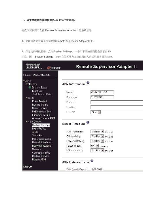
一、设置高级系统管理信息(ASM Information):完成下列步骤来设置Remote Supervisor Adapter II的系统信息:1、登陆到需要设置系统信息的Remote Supervisor Adapter II上;2、在左边的导航栏中,点击System Settings,一个如下图的页面将会显示出来:注意:图中System Settings中的空白的区域内容是由所进入的远程服务器决定的。
3、在ASM Information部分的Name区域,输入Remote Supervisor Adapter II的名称。
使用这个名称可以指定一台服务器中的Remote Supervisor Adapter II,这个名称在e-mail、简单网络管理协议(SNMP)和数字传呼机的报警通知中用于识别来源时都会被用到。
注意:a、如果用户计划建立起一个SMTP简单邮件传输服务器来做邮件方式的报警通知,必须确认在Name区域的名称是可用的邮件地址的一部分。
b、Remote Supervisor Adapter II的名称(在Name区域)和IP主机名称(在Network Interfa ces页面的Host Name区域)不能使用自动共用的同一个名称,因为名称在ASM的Name 区域中被限制在15个字符之内,而在Host Name区域中可以包含63个字符。
为了减少混淆,将Name区域的名称设置为IP Host Name主机名称的一部分。
这个部分的IP Host N ame由完整的IP Host Name的第一段组成。
例如,完整的IP Host Name主机名称是asm ,那么部分的IP Host Name就是asmcard1。
4、在ID number区域,可以为Remote Supervisor Adapter II分配一个唯一的辨认数字。
5、在Contact区域,可以输入联系信息。
例如,用户可以指定一个如果这台服务器发生故障时需要联系的人的名字和电话号码。
Inspur KDB_v1.0_SP1_Installation Guide_v2.1.4_cn

Open Source Software Notice This product includes open source software developed and/or licensed by "OpenSSL," "RSA Data Security, Inc.," "Apache Foundation," "Jean-loup Gailly and Mark Adler," and "Paul Heieh's hash". Information about the afore mentioned and the related open source software can be found in the "${INSTALL_PATH}/license/oss_licenses" directory. 本产品里包含着由“OpenSSL”、“RSA Data Security, Inc.”、“Apache Foundation”、 “Jean-loup Gailly 和 Mark Adler” 以及“Paul Heieh's hash”所开发或者许可的开放源码和软件。有关详细信息,请参看产品目录“${INSTALL_PATH}/li cense/oss_licenses”里的说明内容。
RSA-G2实验室吸收谱仪-H版本 发布于2023年4月说明书
Site Preparation GuideTable of Contents (2)Ideal Setup (3)System Components (4)Instrument Measurements (5)Utility Requirements (6)Computer Requirements .......................................................................................................... 7–8 Hardware (7)Software (8)Accessories (9)ACS and Chiller Panel ................................................................................................... 9–11 Air Dryer .. (12)Liquid Nitrogen Controller (13)Site Preparation Checklist (14)TA Instrument Offices (15)Select a location with adequate floor space and a rigid laboratory bench that is level and is in a vibration-free environment. For optimal performance it is recommended that the instrument beplaced by itself on a separate marble table.Bench width: 2.1 m (7 ft)Bench depth: 76 cm (30 in) min.Distance from the wall: 20 cm (8 in) min.MAIN SYSTEM COMPONENTSA. Computer (Controller)B. InstrumentC. Power Supply EnclosureD. Forced Convection Oven Enclosure E1. Liquid Nitrogen Controller & LN2 TankORE2. Air Cooling SystemMAIN INSTRUMENTPOWER SUPPLY ENCLOSUREFORCED CONVECTION OVEN ENCLOSUREPOWER• 180–264 VAC, 47–63 Hz, and single phase•Dedicated 20 A outlet. US sites require an L6-20 outlet.GASConditions • Must be dry• Must be free from oil (0.01 mg/m 3) and dirt (5 µm)Dew Point* -10°C or betterPressure 100 psig (0.7 MPa)Flow Rate9.5 scfm (270 L/min) If using N 2 gas as FCO heater source, air flow rate is 6 scfm (170 L/min). Separate N 2 gas source must be 70–125 psig and able to sustain a flow rate of 3.5 scfm (100 L/min) *TA Instruments recommends purchasing the air dryer to account for the necessary dew point and air quality.NEMA L6-20 plugHARDWARE REQUIREMENTSProcessor •Intel® Core™ i5 8400 or better• 2.8 GHz with 9 MB L2 cache Memory ≥ 16 GB RAM DDR4 2666 SDRAMHard drive ≥ 80 GB free space• 1.5 GB required for Full version of TRIOS•675 MB required for Lite version of TRIOS (without Online help)DVD (optional) ≥ 48x CD-ROM or DVD (optional for installing TRIOS)Screen resolution Required: 1280 x 1024 with 24-bit colorsRecommended: 1920 x 1080 with 24-bit colorsGraphic memory 128 MBScreen (LCD) size Required: 19” or greaterRecommended: 24” wide screenUSB II port Required with FCO Camera option.Network card Ethernet 10Base T/100 Base TXAdditional Ethernet card(s) Necessary if connecting the instrument directly and access is needed to theCorporate LAN.Ethernet Cabling 10/100BaseTX Ethernet hub/switch. Must be EIA-568B Category 5+ UTP Client-Server Protocol DHCPImage Capture (CameraOption) DirectX 9.0 or higherTCP/IP ports used •TCP: 20010, 20011•UDP: 5050, 5056SOFTWARE REQUIREMENTSItemOperating System •Windows 10 or 11 Enterprise, Ultimate, & Professional •Home version not supported•≥ 64-bit versionInternet Internet connection is strongly recommended for ongoing support after installationService Pack Microsoft Operating System Service PackUpdates Windows Operating System and associated Microsoft updates must be up to date.Windows 10 must be 1709 or later.Network A second network card for corporate connection is recommended. TA Instruments is not responsible for resolving issues associated with connections to your corporate network.Conflicts TA Instruments is not responsible for resolving hardware/software conflicts created by the addition of third-party hardware or software to the computer.ACS-2 MEASUREMENTSACS-3 MEASUREMENTSFCO CHILLER PANEL MEASUREMENTS – SMC MODELFCO CHILLER PANEL MEASUREMENTS – PARKER MODEL (DISCONTINUED)AIR COOLING SYSTEM REQUIREMENTS8A, 9A, 9.1A, or 11A (refer to the serial number plate on the rear of the unit) Circulator Power Cooling Gas LN2Fluid Light Hardware Software Temp Lab CustomerNEMA L6-20 plugAIR DRYER REQUIREMENTScondensation into water (installed by Customer’s maintenance personnel) Circulator Power Cooling Gas LN2Fluid Light Hardware Software Temp Lab CustomerLIQUID NITROGEN CONTROLLER MEASUREMENTSLIQUID NITROGEN CONTROLLER REQUIREMENTSRequirementsShould be placed on the same side as the FCOCustomer must provide: 160 L (or larger) Liquid Nitrogen tank with a pressure of14–22 psig (95–150 kPa gauge)LN 2 pressure above 30 psig (207 kPa gauge) may cause damage to the Liquid Nitrogen Controller. Keep the supply line short and provide adequate insulation to minimize gaseous nitrogen build-up in the supply line. Failure to do so may cause the Liquid Nitrogen Controller to malfunction frequently. Use the 3 ft. hose provided by TA Instruments for this reason.Circulator Power Cooling Gas LN 2 Fluid Light Hardware Software Temp Lab CustomerRSA-G2 Solids AnalyzerFor information on our latest products, contact information, and more, see our website at: .To find your local TA Instruments office and contact information, visit/contact/ta-directory/TA Instruments – Waters LLCCorporate Headquarters159 Lukens DriveNew Castle, DE 19720USATelephone: 302-427-4000Fax: 302-427-4001Email: **********************。
Atmel CryptoAuthentication技术幻灯片说明书
48 bit guaranteed unique serial number
September 09
3
Crypto Products
CryptoAuthentication product family overview
4FUCZ"UNFM DBO`UCFNPEJGJFEJOUIFGJFME
September 09
8
Crypto Products
SA100S SRAM
SRAM Key 0x0000 0xFF FF FF FF FF FF FF FF FF FF FF FF FF FF FF FF FF FF FF FF FF FF FF FF FF FF FF FF FF FF FF FF 1
3FBE "EESFTT
Y
r r
Y Y' Y Y'
3FBE "EESFTT
Y
r r
Y Y' Y Y'
3FBE r "EESFTT
Y r
Y Y' Y Y'
September 09
6
Crypto Products
SA102S/10HS Fuse Mapping
SA102 Fuse Map
3FBE r Y
"EESFTT
Y'
Y
r Y
Y'
Securely transmitted to customer by Atmel One key provided to each customer
产品平台报文接口规范
产品平台报文接口规范1 总体技术方案1.1 通讯方式所有报文域以JSON报文格式,发送到汇宜产品平台。
前端发送交易结果同步响应给商户,如超时仍未得到交易响应,商户可通过发起交易查询获取交易处理结果。
交易状态查询类交易,交易结果同步响应给商户。
1.2 符号约定表1符号约定1.3 签名机制1.3.1.1 报文的签名机制对于报文的签名处理机制如下:首先,对报文中msg_body对象域转换成json字符串,再使用机构RSA私钥证书对该串做签名操作(签名时算法选择SHA-1)。
最后,对签名做Base64编码,将编码后的签名串放在签名(signature)字段中,将报文放在body中,以json方式发送给汇宜产品平台。
1.3.1.2 报文的验签机制对于报文的验签处理机制如下:首先,取出msg_body域值作为待签名串。
其次,使用汇宜机构RSA公钥证书对待签名串和报文中的签名信息做签名验证操作。
报文示例:{"version":"1.0.0","encoding":"UTF-8","signature":"x/nSIrz/lJnVH4Nv+zOB/nGrkJ0r0nDZIMis1UqIxVG/xNMHYN7dqpj/qBl1uFt8O0k o813SC8e8Lnc7W1K/AR01IEn8Lzq1WYnx0qmDIwSrrsQMuRo1D0agOuNlPaL3weKKBAGdUdsahASPURKZ1sXsLP/43r+3ufPvZitnL575xPLKQaZO7xq6ien7ZW4tb 0VGKcj06IQ9AA5zOFANTweIPao+7ttqKysOEF2PY/y0NSN/hFQ0P7Me7XobNXzyZW/kMir/Sa447xwnAs2tkrDQm4h4icNEASFZZltXp1Xwk24obwl4Uc11PnTG2Ix vQwZmyeP4sRJe24y6FWjgwA==","sign_method":"01","msg_body":"{\"ins_id_cd\":\"\",\"prod_cd\":\"1151\",\"biz_cd\":\"\",\"mcht_cd\" :\"9969\",\"tran_dt_tm\":\"201\",\"order_id\":\"\",\"tran_amt\":\"1\",\"qr_code_info\":{\"noti_url\" :\" 8.30.10:8088/prodpmpnotify\"},\"tran_cd\":\"7131\"}"}异步通知正常应答报文样例:{"version":"1.0.0","encoding":"UTF-8","sign_method":"01","msg_body":"{\"ins_id_cd\":\"\" ,\"sys_order_id\":\"2089\",\"tran_cd\":\"6132\",\"resp_cd\":\"00\",\"resp_msg\":\"成功\"}"}1.3.2 加密方式1.3.2.1 交易PIN对于持卡人密码汇宜产品平台使用RSA公钥证书对ANSI X9.8带主帐号格式的PIN加密并做Base64编码后传输,以保障密码的安全性。
- 1、下载文档前请自行甄别文档内容的完整性,平台不提供额外的编辑、内容补充、找答案等附加服务。
- 2、"仅部分预览"的文档,不可在线预览部分如存在完整性等问题,可反馈申请退款(可完整预览的文档不适用该条件!)。
- 3、如文档侵犯您的权益,请联系客服反馈,我们会尽快为您处理(人工客服工作时间:9:00-18:30)。
RSA交易监控产品可扩展性
不断进化升级的认证平台兼容性, 能够为银行提供多样的、 跨平台的认证手段,易于管理,且不断升级。
RSA CPS能够支持最广泛的认证手段,包括数字证书、动 态令牌、刮刮卡、静态密码、带外认证、反向认证等等,均 能够根据银行现有认证手段进行灵活集成,与网银现有认证 平台提供无缝的整合
RSA消费者保护套件(CPS)
防欺诈检测( 防欺诈检测(Fraud Action) )
• • • • • • • • •
业内首个反钓鱼和反域名攻击的解决方案 RSA反欺诈命令中心(AFCC)专家团队全天候支持 主动应对技术(RCT)和根源分析(RCA)等多项安全技术专利
自适应认证( 自适应认证(Adaptive Authentication) )
案例分析: 交易监控产品应用效果
在不到3周的时间内部署于某英国前三大银行之一 减少了83%的在线银行欺诈交易,每7000笔中仅有1 笔交易被标识 仅需要2名交易分析管理员处理标识实例 威慑效果显著: 钓鱼、木马等攻击 行为显著减少
RSA交易监控解决方案特点
技术领先,模块多元化 良好的可扩展性,支持银行现有各种认证方式 超过9000家银行企业用户,丰富的案例资源供分享 RSA多年丰富的专业实施经验 本地的强大的技术支持团队 本地化,对双字节平台的支持和管理界面的汉化定制 产品功能强大、部署简便,模块简洁,易于集成,无需代理
RSA® eFraudNetwork™:全球最大的防网上欺诈机构
eFraudNetwork在全球超 过130个国家追踪记录欺诈 者档案和行为模式,成员 机构实时分享信息 跨应用、跨平台的欺诈检 测能力显著提高了欺诈检 测率,并将跨机构在线检 测欺诈活动的周期和效率 由天降至小时以内 包括微软、AOL在内的全 球各主要IT厂商和ISP均选 择RSA eFraudnetwork作 为他们的反欺诈引擎,如 IE7内置的防钓鱼功能
超过9000家大型机构采用 RSA消费者保护套件,保护 全球超过1亿的在线交易用 户
全美前40家银行,英国60% 的大银行均采用了RSA消费 者保护套件,提高了网银的安 全性,提升了银行的信誉和知 名度
Bank Of America
BOA在2005年6月布署了RSA消费者保护套件
全部网银用户超过2000万,日交易量超过2600万笔,均 在RSA的CPS保护之中
RSA 消费者保护套件业界评论
#1 Best Security Innovation, Future Now List (Financial IT Security) Best Authentication and Fraud Detection Suite (Aite Group) Best Global Security Company 2006 (SC Magazine) Top 100 Vendors (IT Week) Product of the Year 2006 (Information Security Magazine) Best Products of 2005 (Business Week) Best of 2005 (Online Banking Reports) “…the tool of choice for financial institutions protecting their online banking customers…” (Business 2.0)
RSA智能风险分析引擎(RRE),通过众多专利技术如自学习、主动采样、 链路着色等,能够根据现有逻辑和数据进行分析并自主升级,应对不断 演化的高风险行为模式
RSA交易监控体系结构
支持各主流操作系统平台,如HP-UX、Solaris、AIX、 Windows
支持各主流应用服务器,如Weblogic 、 WebSphere 、IIS、 Tomcat Tomcat等
BOA及其网银客户对RSA的解决方案给予高度评价
RSA交易监控(TM)产品特点 交易监控( ) 交易监控
RSA交易监控产品受益
RSA风险引擎自学习智能应对未知风险 对抗所有现有暴露出的威胁 显著降低在线欺诈损失 不改变用户体验 与银行现有认证方式交互,无缝集成 可在4周内部署完毕
Client Quote: ”The system is innovative and works far better than traditional tools that were never designed to meet the challenge of Internet fraud.”
- Gordon McFadyen, HBOS Fraud Dept (Oct, 2005)
TM产品架构
监控
识别
调查
RSA交易监控产品
监控 在线行为透明监控
识别 判定高风险行为,标识并建议适当的应对
调查 使银行能够有效地调查高风险交易
银行可自行选择是否对可疑交易进行二次认证 二次认证
防木马和防中间人攻击
RSA® 网银交易监控(TM)产品 网银交易监控( )
RSA the Security Division of EMC July. 2007
提 纲
RSA消费者保护套件(CPS)简介 RSA交易监控(TM)应用案例 RSA交易监控(TM)方案特点
• • • • • • •
产品模块 防木马和防中间人攻击 体系架构 建行网银平台建议配置 系统部署 可扩展性 本地支持
支持各主流数据库系统,如ORACLE 、 DB2等
支持J2EE、SOAP、Web Service等开发平台或协议
RSA交易监控产品部署方式
多种部署选择以适合银行的最佳需求:
• • •
业务目标Байду номын сангаасIT资源 运营风险
部署地点: 银行本地 / ASP 集成方式:
• • • •
Web Services (SOAP) – 同步API Beacon – HTML页面插件,将数据发送给RSA server Log File Feed – 传送服务器日志和相关资源数据进行分析 Web Filter – web server filter, 无需任何编程
RSA将繁多的木马根据行为归纳为以下数类: • Phishing/Pharming Trojans • Page in the middle • Keyloggers/Screenscrapers • Active Trojans (Man in the Middle Trojan) • Active Keylogger + Proxy (Botnet) Trojan RSA不断研究木马和中间人攻击等行为模式,通过深入分析和归纳,将 以上各类木马行为检测能力整合入RSA交易监控产品,成为业内领先的 成为业内领先的 和唯一的将交易监控与防木马、 和唯一的将交易监控与防木马、防中间人攻击有机结合的解决方案
RSA交易监控产品应用案例 交易监控产品应用案例
RSA CPS应用案例
Bank of America(2000万用户) CITI BANK(2000万用户) ING HSBC Credit Suisse(200万用户) Barclays(170万用户) E-Trade HBOS Washington Mutual 日本Mizuho Bank 日本Sumitomo Mitsui Bank 日本 ……
第三方机构评估——Aite Group
•
“作为市场上最完整的解决方案,RSA CPS还可以提供电话渠道认 证、在线新威胁保护服务、凭证漫游服务等。我们相信通过硬件、 软件认证平台以及欺诈交易检测解决方案的整合,RSA已经成为在 线银行安全市场的领导者。”
——Aite Group.《Online Banking Authentication And Fraud Detection: A Vendor Comparison》第36页
更可与CPS其它模块无缝集成,包括自适应认证、反欺诈、 GO ID网络认证服务、电话银行认证、站点反向认证、KBA 基于知识库的认证等
RSA交易监控产品技术支持
国内拥有超过500人的技术服务团队进行本地支持和响应
北京和上海分别设有研发中心,研发团队两年内将达到 1000人
RSA全球AFCC安全专家团队,监控全球网络安全,为客户 提供全天侯安全服务
RSA交易监控方案小结 第三方机构评估参考
RSA消费者保护套件 消费者保护套件
(RSA Consumer Protection Suite) )
RSA 消费者保护套件 消费者保护套件:端到端的多层次保护
三大功能模块可独立实现,亦可互相有机结合, 三大功能模块可独立实现,亦可互相有机结合, 并按客户需要分批实施
基于风险评估的身份认证平台 丰富的辅助身份认证方法选择,与银行现有的各种认证技术无缝兼容 可以动态调整认证级别,智能匹配银行业务需求
交易监控( 交易监控(Transaction Monitoring) )
透明地监控每一个交易行为,根据用户资料、行为、交易习惯等超过百种 风险因子进行智能分析 灵活、多样的集成方式供银行选择,4周即可部署完毕 独特的体系架构设计和优化的分析引擎算法,在实现业界最优的预测准确 率和低误判率的同时,对银行现有系统影响最低