5-1462000-5中文资料
1956153资料

Extract from the onlinecatalogCCVA 2,5/ 9-G-5,08 RNP26THROrder No.: 1956153The figure shows a 10-position version of the producthttp://eshop.phoenixcontact.de/phoenix/treeViewClick.do?UID=1956153Headers, with engagement nose, pin length: 2.6 mm, 5.08 mm pitch, 9-pos.http://Please note that the data givenhere has been taken from theonline catalog. For comprehensiveinformation and data, please referto the user documentation. TheGeneral Terms and Conditions ofUse apply to Internet downloads. Technical dataDimensions / positionsPitch 5.08 mmDimension a40.64 mmNumber of positions9Pin dimensions 1 x 1 mmPin spacing 5.08 mmHole diameter 1.6 mmTechnical dataInsulating material group IIIaRated surge voltage (III/3) 4 kVRated surge voltage (III/2) 4 kVRated surge voltage (II/2) 4 kVRated voltage (III/2)320 VRated voltage (II/2)400 VConnection in acc. with standard EN-VDENominal current I N12 ANominal voltage U N250 VMaximum load current12 A (per position)Insulating material LCPInflammability class acc. to UL 94V0Certificates / ApprovalsApproval logoCULNominal voltage U N300 VNominal current I N10 AULNominal voltage U N300 VNominal current I N10 ACertification CUL, ULAccessoriesItem Designation DescriptionGeneral1954362CR-MSTB NAT HT HT coding section, is pushed into the recess on the header beforethe reflow process, made of highly temperature-resistant, beigeinsulating materialMarking1051993B-STIFT Marker pen, for manual labeling of unprinted Zack strips, smear-proof and waterproof, line thickness 0.5 mm0804293SK 5,08/3,8:FORTL.ZAHLEN Marker card, printed horizontally, self-adhesive, 12 identicaldecades marked 1-10, 11-20 etc. up to 91-(99)100, sufficient for120 terminal blocks0805085SK 5,08/3,8:SO Marker card, special printing, self-adhesive, labeled acc. tocustomer requirements, 12 identical marker strips per card, max.25-position labeling per strip, color: white0805412SK 5,08/3,8:UNBEDRUCKT Marker cards, unprinted, with pitch divisions, self-adhesive, 10-section marker strips, 12 strips per card, can be labeled with theM-PENPlug/Adapter1734401CR-MSTB Coding section, inserted into the recess in the header or theinverted plug, red insulating materialDrawingsApplication drawingDrilling diagramDimensioned drawingBottom view, free space for solder paste, 0.55mm deepAddressPHOENIX CONTACT GmbH & Co. KGFlachsmarktstr. 832825 Blomberg,GermanyPhone +49 5235 3 00Fax +49 5235 3 41200http://www.phoenixcontact.de© 2008 Phoenix ContactTechnical modifications reserved;。
PSR05中文资料
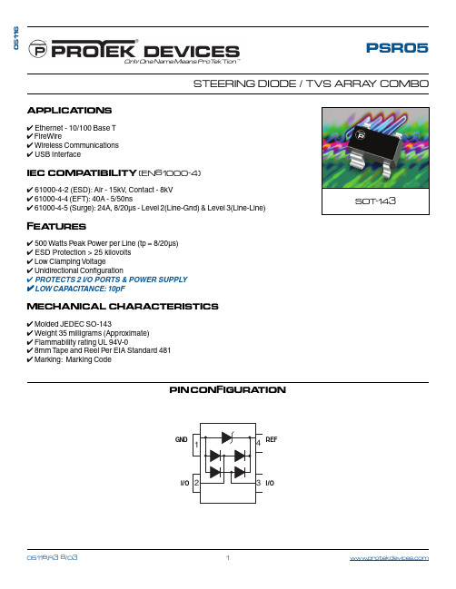
PSR05STEERING DIODE / TVS ARRA Y COMBOOnly One Name Means ProTek’Tion™APPLICA TIONS ✔ Ethernet - 10/100 Base T✔ FireWire✔ Wireless Communications ✔ USB InterfaceIEC COMP A TIBILITY (EN61000-4)✔ 61000-4-2 (ESD): Air - 15kV , Contact - 8kV ✔ 61000-4-4 (EFT): 40A - 5/50ns✔ 61000-4-5 (Surge): 24A, 8/20µs - Level 2(Line-Gnd) & Level 3(Line-Line)FEA TURES✔ 500 Watts Peak Power per Line (tp = 8/20µs)✔ ESD Protection > 25 kilovolts ✔ Low Clamping Voltage✔ Unidirectional Configuration✔ PROTECTS 2 I/O PORTS & POWER SUPPLY ✔ LOW CAPACITANCE: 10pFMECHANICAL CHARACTERISTICS ✔ Molded JEDEC SO-143✔ Weight 35 milligrams (Approximate)✔ Flammability rating UL 94V-0✔ 8mm Tape and Reel Per EIA Standard 481✔ Marking: Marking Code05116PIN CONFIGURA TIONSOT -143GNDI/OREFI/ODEVICE CHARACTERISTICSNote 1: As shown in Figure 5, REF 1 is connected to ground, REF 2 is connected to +V CC and input applies to V CC = 5V , V sign = 30mV , F = 1MHz.ELECTRICAL CHARACTERISTICS PER LINE @ 25°C Unless Otherwise SpecifiedPART NUMBERMINIMUM BREAKDOWN VOLTAGE@ 1A V (BR)VOLTS MAXIMUM CLAMPING VOLTAGE (See Fig. 2)@ I P = 1AV C VOLTS MAXIMUM CLAMPING VOLTAGE (See Fig. 2)8/20µs V C @ I PP VOLTS MAXIMUM CAPACITANCE (See Note 1)(See Fig. 5)(Per Data Line)@0V , 1 MHzC J(SD)pFPSR056.09.820.0V @ 28.0A10MAXIMUM LEAKAGE CURRENT@V WMI D µA 5.0RATED ST AND-OFF VOLTAGEV WM VOLTS5.0DEVICE MARKING5AMAXIMUN RATINGS @ 25°C Unless Otherwise SpecifiedOperating T emperature SYMBOL VALUE -55°C to 150°C°C °C -55°C to 150°C UNITS T J T STG PARAMETERStorage T emperaturePeak Pulse Power (t p = 8/20µs) - See Figure 1P PP 500Watts Peak Forward Voltage - I F = 1A, 8/20µsVolts1.5VF0 5 10 15 20 25 30t - Time - µs20406080100120I P P - P e a k P u l s e C u r r e n t - % o f I P PFIGUR E 20.01 1 10 100 1,000 10,000t d - Pulse Duration - µs101001,00010,000P P P - P e a k P u l s e C u r r e n t - W a t t sFIGUR E 1PEAK PULSE POWER VS PULSE TIMEGRAPHSFIGUR E 5INPUT CAPACITANCE CIRCUITCCV SIGNT L - Lead T emperature - °C20406080100% O f R a t e d P o w e rFIGUR E 3FIGUR E 4OVER SHOOT & CLAMPING VOLTAGE FOR PSR 05ESD Test Pulse: 5 kilovolt, 1/30ns (waveform)5 V o l t s p e r D i v i s i o n-20-101020FIGUR E 6TYPICAL REVERSE VOLTAGE VS CAPACITANCE FOR PSR050 1 2 3 4 5V R - Reverse Voltage - VoltsC - C a p a c i t a n c e - p F481216APPLICA TION NOTEThe PSR05 is a low capacitance, bidirectional TVS array that is designed to protect I/O or high speed data lines from the damaging effects of ESD or EFT. This product series has a surge capability of 500 Watts PPPper line for an 8/20µs waveform and offers ESD protection > 25kV.COMMON-MODE CONFIGUR ATION (Figure 1)Ideal for use in USB applications, two PSR05 devices provides up to two(2) lines of protection(per device) in a common-mode configuration as depicted in Figure 1.Circuit connectivity is as follows:✔Pins 2 and 3 are connected to the datalines.✔Pin 1 is connected to ground.✔Pin 4 is connected to the databus.CIR CUIT BOAR D LAYOUT R ECOMMENDATIONS Circuit board layout is critical for Electromagnetic Compatibility (EMC) protection. The following guidelines are recommended:✔The protection device should be placed near the input terminals or connectors, the device willdivert the transient current immediately before itcan be coupled into the nearby traces.✔The path length between the TVS device and the protected line should be minimized.✔All conductive loops including power and ground loops should be minimized.✔The transient current return path to ground should be kept as short as possible to reduceparasitic inductance.✔Ground planes should be used whenever possible. For multilayer PCBs, use ground vias.Figure 1. T ypical Common-Mode USB ProtectionCOPYR IGHT © ProTek Devices 2003SPECIFICA TIONS: ProT ek reserves the right to change the electrical and or mechanical characteristics described herein without notice (except JEDEC).DESIGN CHANGES: ProT ek reserves the right to discontinue product lines without notice, and that the final judgement concerning selection and specifications is the buyer ’s and that in furnishing engineering and technical assistance, ProTek assumes no responsibility with respect to the selection or specifications of such products.P ACKAGE OUTLINE & DIMENSIONSProTek Devices2929 South Fair Lane, Tempe, AZ 85282Tel: 602-431-8101 Fax: 602-431-2288E-Mail: sales@ Web Site: 。
2015年最新EN14362-2(中文版)资料

第二部分:通过萃取纤维法测定禁用偶氮染料的含量本欧洲标准享有英国国家标准等同效力。
ICS 59.080.30未经BSI允许,本标准不得翻版。
纺织品可释放出特定芳香胺的偶氮染料的测试方法第二部分萃取纤维法测定禁用偶氮染料的含量前言该文件(EN 14362-1:2003)由“纺织和纺织产品”技术委员会CEN/TC248编写,秘书处由BSI 执行。
本欧洲标准必须于2004年4月前通过发表与之内容相同的文本或背书而具备国家标准的效力,与此标准相悖的国家标准须于2004年4月前废除。
附录A,C和D是信息化的,附录B是标准化的。
如果未实施适当的防范措施,该欧洲标准所要求使用的物质和/或步骤对健康有一定的伤害。
它只提供技术适宜性并不免除使用者在任何阶段对于健康和安全的法律义务。
根据CEN/CENELEC的内部规章,下列国家的标准化组织必须执行本标准:奥地利、比利时、捷克共和国、丹麦、芬兰、法国、德国、希腊、冰岛、爱尔兰、意大利、卢森堡、马耳他、荷兰、挪威、葡萄牙、西班牙、瑞典、瑞士和英国。
1 范围EN-14362这一部分描述了特定偶氮染料的检测步骤,该类偶氮染料不能用于日用纺织品的生产和加工过程,适用于用可萃取的染料染色的人造纤维。
直接的测试方法见EN 14362-1。
非萃取法测定禁用偶氮染料的含量对于某些混合纤维该标准的两种方法都可以使用。
2. 规范性参考文件本标准引用了一些其他出版物中注明或未注明日期的文件及条款。
这些规范性引用文件在本文中适当部分被引用时,随后列明了引用的出版物名称。
凡注明日期的引用文件,其出版后的任何修正或更改内容只有在本标准中注明才有效。
凡未注明日期的引用文件,其最新版本(包括修正)适用于本标准。
EN ISO 3696,分析实验用水—规格和试验方法(ISO 3696:1987)ISO 4787,实验室玻璃器具类—测定体积的玻璃器具—使用和测试容量的方法3 概述根据2002/61/EC法令,下表禁止使用的可裂解芳香胺。
4562 铜箔

IPCIPC-4562印制板用金属箔IPC-45622000年5月IPC-4562 印制板用金属箔2000.051范围本规范规定了用于印制板的载体和非载体金属箔的要求。
除非供需双方另有规定,符合本规范的金属箔应被认为是可以接受的。
1.1目的本规范只规定印制板用金属箔的采购要求。
1.2分类标识如下体系用于标识金属箔。
1.2.1详细规范的说明在本规范末尾列有一系列的详细规范。
每个详细规范都列出了一种金属箔的工程和性能数值,并有一个编号,供订购材料使用。
例如,如果某用户希望订购详细规范编号为1的材料,那么上述编号示例中的“X”应由“1”代替(例如IPC-4562/1)。
本规范包括了现有已知的材料,当新材料出现时,它将被加入到本规范的修订版中。
鼓励使用者和材料开发者提供新材料的信息给金属箔任务工作组(3-12a)评审。
使用者希望未列入本规范的金属箔援引本规范时,应以0作为其详细规范的编号(例如IPC-4562/0)。
本规范提供了各种质量分级(见1.2.3~1.2.7),以反映出功能性能(见附录A)和试验性能。
选择某一质量等级后,并不能排除再去援引在其他等级中规定的特定要求。
1.2.2 金属箔金属箔应以2个或3个字母作为其代号:CU――铜箔NI――镍XX――其它1.2.3 箔类型金属箔类型按其加工工艺划分如下:E――电解的W――压延的O――其它1.2.4 箔等级IPC-45621.2.4.1 箔等级箔等级应按下面的等级代号进行标识:1.标准电解箔(STD-Type E)2.高延伸性电解箔(HD-Type E)3.高温延伸率电解箔(HTE-Type E)4.退火电解箔(ANN-Type E)5.压延锻造箔(AR-Type W)6.轻冷压延锻造箔(LCR-Type W)7.退火锻造箔(ANN-TYPE W)8.压延锻造可低温退火箔(LTA-Type W)9.标准电解镍箔10.可低温退火电解箔(LTA-Type E)11.可退火电解箔(A-Type E)1.2.4.2 其它金属箔型号其它金属箔型号将在有需要时进行规定。
5962-9571001MUA资料

Symbol
Line Regulation Load Regulation Dropout Voltage
VRLN VRLD VD O
-6 V
VIN -26 V, 5 mA I OUT = IO U T 1.0 A
50 mA
I . 1A O = 0 DV O 100 mV I O = 1.0 A DV O 100 mV
1 . 1 1 . 3 1 . 3 1 . 4
DESCRIPTION
The OM2990 series of fixed voltage regulators are designed to provide up to 1.5A with h i g he ff i c i e n c y. It has the ability to source 1A of output current with a typical dropout voltage of 0.6V and a maximum of 1V over the entire operating temperature range. It is supplied in hermetic packages and is ideally suited for all applications where small size and high reliability are required.
TA
125°C, VIN = 1 0V , COUT = 4 7µ F ( u n l e s so t h e r w i s es p e c i f i e d ) .
Test Conditions 5 mA < I . 0A O < 1 I O < 1.0A I O = 1.0A , VI N = -5 V
1956182资料

Extract from the onlinecatalogCCVA 2,5/12-G-5,08 RNP26THROrder No.: 1956182The figure shows a 10-position version of the producthttp://eshop.phoenixcontact.de/phoenix/treeViewClick.do?UID=1956182Headers, with engagement nose, pin length: 2.6 mm, 5.08 mm pitch, 12-pos.http://Please note that the data givenhere has been taken from theonline catalog. For comprehensiveinformation and data, please referto the user documentation. TheGeneral Terms and Conditions ofUse apply to Internet downloads. Technical dataDimensions / positionsPitch 5.08 mmDimension a55.88 mmNumber of positions12Pin dimensions 1 x 1 mmPin spacing 5.08 mmHole diameter 1.6 mmTechnical dataInsulating material group IIIaRated surge voltage (III/3) 4 kVRated surge voltage (III/2) 4 kVRated surge voltage (II/2) 4 kVRated voltage (III/2)320 VRated voltage (II/2)400 VConnection in acc. with standard EN-VDENominal current I N12 ANominal voltage U N250 VMaximum load current12 A (per position)Insulating material LCPInflammability class acc. to UL 94V0Certificates / ApprovalsApproval logoCULNominal voltage U N300 VNominal current I N10 AULNominal voltage U N300 VNominal current I N10 ACertification CUL, ULAccessoriesItem Designation DescriptionGeneral1954362CR-MSTB NAT HT HT coding section, is pushed into the recess on the header beforethe reflow process, made of highly temperature-resistant, beigeinsulating materialMarking1051993B-STIFT Marker pen, for manual labeling of unprinted Zack strips, smear-proof and waterproof, line thickness 0.5 mm0804293SK 5,08/3,8:FORTL.ZAHLEN Marker card, printed horizontally, self-adhesive, 12 identicaldecades marked 1-10, 11-20 etc. up to 91-(99)100, sufficient for120 terminal blocks0805085SK 5,08/3,8:SO Marker card, special printing, self-adhesive, labeled acc. tocustomer requirements, 12 identical marker strips per card, max.25-position labeling per strip, color: white0805412SK 5,08/3,8:UNBEDRUCKT Marker cards, unprinted, with pitch divisions, self-adhesive, 10-section marker strips, 12 strips per card, can be labeled with theM-PENPlug/Adapter1734401CR-MSTB Coding section, inserted into the recess in the header or theinverted plug, red insulating materialDrawingsApplication drawingDrilling diagramDimensioned drawingBottom view, free space for solder paste, 0.55mm deepAddressPHOENIX CONTACT GmbH & Co. KGFlachsmarktstr. 832825 Blomberg,GermanyPhone +49 5235 3 00Fax +49 5235 3 41200http://www.phoenixcontact.de© 2008 Phoenix ContactTechnical modifications reserved;。
14620.2-2006罐的设计和建造规范标准
BS EN14620-2-2006低温工作条件下立式平底圆筒型储罐"第二部分储存最低温度达-165度的液化气的单容、双容和全容金属罐的设计和建造规范"[2010-06-13]Contents目录1.范围 (4)2.引用标准 (4)3.术语和定义 (6)3.1 应变振幅 (6)3.2 递进变形 (6)3.3 应变范围 (6)3.4 棘轮效应 (6)3.5 不稳定倒塌 (6)4.材料 (6)4.1 总述 (6)4.2 温度 (6)4.3 主要和二级液体储存罐 (6)4.4 蒸汽罐/外罐 (9)4.5 其他部件 (9)5.设计 (10)5.1 设计理论 (10)5.2 主要和二级液体罐 (12)5.3 蒸汽罐(外罐) (22)5.4 吊顶 (26)5.5接管 (26)5.6 内外罐的底板连接 (29)5.7 罐与罐之间的连接 (29)5.8 其他细节 (29)6 制作 (30)6.1 材料处理 (30)6.2 钢板预制与公差 (30)6.4 拱顶 (33)6.5 临时附件 (33)7 焊接程序 (34)7.1 总述 (34)7.2 WPAR要求 (34)7.3 应力试验 (34)7.4 9%镍钢 (34)7.5 焊工和自动焊工 (35)7.6 产品试验板 (35)8. 焊接 (35)8.1 定位焊及临时焊 (35)8.2 气候条件 (36)8.3 预热 (36)8.4 焊后热处理 (36)9. 检测 (37)9.1 NDE人员资格 (37)9.2 检测程序 (37)9.3 检查类别 (37)9.4 目视检测 (39)9.5 渗透检测 (40)9.6 磁粉粒子检测 (40)9.7 真空盒检测 (40)9.8 氨气气密性试验 (40)9.9 皂泡检测 (40)9.10 射线检测 (41)9.11 超声波检测 (41)9.12 验收准则 (41)9.13 环缝的不可接受缺陷 (42)9.14 打磨完成后的可接受厚度 (42)1.范围本欧标规定了冷冻液化天然气储存罐金属部件的材料、设计、施工和安装的总体要求。
5962-9089911MXX资料

STANDARDMICROCIRCUIT DRAWINGDEFENSE SUPPLY CENTER COLUMBUSCOLUMBUS, OHIO 43216-5000SIZEA5962-90899REVISION LEVELCSHEET3DSCC FORM 2234 APR 971.2.5 Lead finish. The lead finish is as specified in MIL-PRF-38535 for device classes Q and V or MIL-PRF-38535, appendix A for device class M.1.3 Absolute maximum ratings. 1/Endurance:Device types 01-04, 09.....................................10,000 cycles/byte, minimum Device types 05-08........................................1,000 cycles/byte, minimum Device types 10-13........................................100,000 cycles/byte, minimum Supply voltage range (V ) 2/................................-2.0 V dc to +7.0 V dc CC Storage temperature range (T )..............................-65 C to +150 C stg Maximum power dissipation (P )..............................1.0 W D Lead temperature (soldering, 10 seconds).......................+300 C Junction temperature (T ) 3/.................................+150 CJ Thermal resistance, junction-to-case ( ) (case outline X, Y)......See MIL-STD-1835JC Thermal resistance, junction-to-case ( ) (case outlines T, Z)......13 C/W JC Thermal resistance, junction-to-case ( ) (case outline U).........27 C/WJC Voltage on any pin with respect to ground 2/.....................-2.0 V dc to +7.0 V dc Voltage on pin A with respect to ground 4/.....................-2.0 V dc to +13.5 V dc 9V supply voltage with respect to ground 4/....................-2.0 V dc to +14.0 V dc PP V supply voltage with respect to ground 2/....................-2.0 V dc to +7.0 V dc CC Output short circuit current 5/.................................200 mAData retention .............................................10 years minimum1.4 Recommended operating conditions. 6/Supply voltage range (V )..................................+4.5 V dc to +5.5 V dc CC Operating temperature range (T )...........................-55 C to +125 Ccase Low level input voltage range (V ).............................-0.5 V dc to +0.8 V dcIL High level input voltage range (V )............................+2.0 V dc to V +0.5 V dcIH CC High level input voltage range, CMOS (V )......................V -0.5 V dc to V +0.5 V dc IH CC CC Chip clear (V ).............................................11.4 V dc to 12.6 V dc P 1.5 Digital logic testing for device classes Q and V.Fault coverage measurement of manufacturinglogic tests (MIL-STD-883, test method 5012)....................100 percent1/Stresses above the absolute maximum rating may cause permanent damage to the device. Extended operation at themaximum levels may degrade performance and affect reliability.2/Minimum dc voltage on input or V pins is -0.5 V. During voltage transitions, inputs may overshoot V to -2.0 V forO SS periods of up to 20 ns. Maximum dc voltage on output and V pins is V +0.5 V. During voltage transitions outputs O CC may overshoot to V +2.0 V for periods up to 20 ns.CC 3/Maximum junction temperature shall not be exceeded except for allowable short duration burn-in screening conditions inaccordance with method 5004 of MIL-STD-883.4/Minimum dc input voltage on A or V may overshoot to +14.0 V for periods less than 20 ns.9PP 5/No more than one output shorted at a time. Duration of short circuit should not be greater than 1 second.6/All voltages are referenced to V (ground).SSSTANDARDMICROCIRCUIT DRAWINGDEFENSE SUPPLY CENTER COLUMBUSCOLUMBUS, OHIO 43216-5000SIZEA5962-90899REVISION LEVELCSHEET4DSCC FORM 2234 APR 972. APPLICABLE DOCUMENTS2.1 Government specification, standards, and handbooks. The following specification, standards, and handbooks form a part of this drawing to the extent specified herein. Unless otherwise specified, the issues of these documents are those listed in the issue of the Department of Defense Index of Specifications and Standards (DoDISS) and supplement thereto, cited in the solicitation.SPECIFICATIONDEPARTMENT OF DEFENSEMIL-PRF-38535 - Integrated Circuits, Manufacturing, General Specification for.STANDARDSDEPARTMENT OF DEFENSE MIL-STD-883-Test Method Standard -STD-973-Configuration Management.MIL-STD-1835-Interface Standard for Microcircuit Case Outlines.HANDBOOKSDEPARTMENT OF DEFENSE MIL-HDBK-103-List of Standard Microcircuit Drawings (SMD's).MIL-HDBK-780-Standard Microcircuit Drawings.(Unless otherwise indicated, copies of the specification, standards, and handbooks are available from the Standardization Document Order Desk, 700 Robbins Avenue, Building 4D, Philadelphia, PA 19111-5094).2.2 Non-Government publications. The following documents form a part of this document to the extent specified herein. Unless otherwise specified, the issues of the documents which are DoD adopted are those listed in the issue of the DODISS cited in the solicitation. Unless otherwise specified, the issues of documents not listed in the DODISS are the issues of the documents cited in the solicitation.AMERICAN SOCIETY FOR TESTING AND MATERIALS (ASTM)ASTM Standard F1192-95 - Standard Guide for the Measurement of Single Event Phenomena from Heavy Ion Irradiation of Semiconductor Devices.(Applications for copies of ASTM publications should be addressed to the American Society for Testing and Materials,1916 Race Street, Philadelphia, PA 19103).ELECTRONICS INDUSTRIES ASSOCIATION (EIA)JEDEC Standard EIA/JESD78 - IC Latch-Up Test.(Applications for copies should be addressed to the Electronics Industries Alliance, 2500 Wilson Blvd., Arlington, VA 22201.)(Non-Government standards and other publications are normally available from the organizations that prepare or distribute the documents. These documents also may be available in or through libraries or other informational services).2.3 Order of precedence. In the event of a conflict between the text of this drawing and the references cited herein, the text of this drawing shall take precedence. Nothing in this document, however, supersedes applicable laws and regulations unless a specific exemption has been obtained.STANDARDMICROCIRCUIT DRAWINGDEFENSE SUPPLY CENTER COLUMBUSCOLUMBUS, OHIO 43216-5000SIZEA5962-90899REVISION LEVELCSHEET5DSCC FORM 2234 APR 973. REQUIREMENTS3.1 Item requirements. The individual item requirements for device classes Q and V shall be in accordance with MIL-PRF-38535 and as specified herein or as modified in the device manufacturer's Quality Management (QM) plan. The modification in the QM plan shall not affect the form, fit, or function as described herein. The individual item requirements for device class M shall be in accordance with MIL-PRF-38535, appendix A for non-JAN class level B devices and as specified herein.3.2 Design, construction, and physical dimensions. The design, construction, and physical dimensions shall be asspecified in MIL-PRF-38535 and herein for device classes Q and V or MIL-PRF-38535, appendix A and herein for device class M.3.2.1 Case outline(s). The case outline(s) shall be in accordance with 1.2.4 herein and figure 1.3.2.2 Terminal connections. The terminal connections shall be as specified on figure 2.3.2.3 Truth tables. The truth tables shall be as specified on figure 3.3.2.3.1 Unprogrammed devices. The truth table for unprogrammed devices for contracts involving no altered item drawing shall be as specified on figure 3 herein. When required, in screening (see4.2 herein), or quality conformance inspection groups A, B, C, or D (see 4.4 herein), the devices shall be programmed by the manufacturer prior to test in a checkerboard or similar pattern (a minimum of 50 percent of the total number of bits programmed).3.2.3.2 Programmed devices. The requirements for supplying programmed devices are not part of this document.3.2.3.3 Command definitions. The command definitions table shall be as specified on figure 3.3.2.4 Switching test circuits and waveforms. The switching test circuits and waveforms shall be as specified on figure4.3.3 Electrical performance characteristics and postirradiation parameter limits. Unless otherwise specified herein, the electrical performance characteristics and postirradiation parameter limits are as specified in table I and shall apply over the full case operating temperature range.3.4 Electrical test requirements. The electrical test requirements shall be the subgroups specified in table IIA. The electrical tests for each subgroup are defined in table I.3.5 Marking. The part shall be marked with the PIN listed in 1.2 herein. In addition, the manufacturer's PIN may also be marked as listed in MIL-HDBK-103. For packages where marking of the entire SMD PIN number is not feasible due to space limitations, the manufacturer has the option of not marking the "5962-" on the device. For RHA product using this option, the RHA designator shall still be marked. Marking for device classes Q and V shall be in accordance with MIL-PRF-38535. Marking for device class M shall be in accordance with MIL-PRF-38535, appendix A.3.5.1 Certification/compliance mark. The certification mark for device classes Q and V shall be a "QML" or "Q" as required in MIL-PRF-38535. The compliance mark for device class M shall be a "C" as required in MIL-PRF-38535, appendix A.3.6 Certificate of compliance. For device classes Q and V, a certificate of compliance shall be required from a QML-38535listed manufacturer in order to supply to the requirements of this drawing (see 6.6.1 herein). For device class M, a certificate of compliance shall be required from a manufacturer in order to be listed as an approved source of supply in MIL-HDBK-103 (see 6.6.2 herein). The certificate of compliance submitted to DSCC-VA prior to listing as an approved source of supply for this drawing shall affirm that the manufacturer's product meets, for device classes Q and V, the requirements of MIL-PRF-38535and herein or for device class M, the requirements of MIL-PRF-38535, appendix A and herein.3.7 Certificate of conformance. A certificate of conformance as required for device classes Q and V in MIL-PRF-38535 or for device class M in MIL-PRF-38535, appendix A shall be provided with each lot of microcircuits delivered to this drawing.3.8 Notification of change for device class M. For device class M, notification to DSCC-VA of change of product (see 6.2 -herein) involving devices acquired to this drawing is required for any change as defined in MIL-STD-973.STANDARDMICROCIRCUIT DRAWING DEFENSE SUPPLY CENTER COLUMBUS COLUMBUS, OHIO 43216-5000SIZEA5962-90899 REVISION LEVELCSHEET6DSCC FORM 2234 APR 97TABLE I. Electrical performance characteristics.Test Symbol Conditions-55 C T +125 C 1/C4.5 V V5.5 VCCunless otherwise specifiedGroup ASubgroupsDevicetypeLimits UnitsMin MaxDC CHARACTERISTICSInput leakage current I LI V=V max,CC CCV = V max or VIN CC SS1, 2, 3 All ±1.0 µAOutput leakage current I LO V=V max,CC CCV = V max or VOUT CC SS1, 2, 3 All ±10 µAV standby CCcurrent (TTL)I CCS1V=V max,C E = VCC CC IH 1, 2, 3 All 1.0 mAV standby CCcurrent (CMOS)I CCS2C E = V ±0.2 V,CCV=V maxCC CC1, 2, 3 All 100 µAV active read CCcurrent I CC1V=V max,C E = VCC CC ILI = 0 mA, f = 6.0 MHz,OUTO E = V IH1, 2, 3 All 30 mAV programming CCcurrent I CC2C E = V, programming inILprogress1, 2, 3 All 30 2/mAV erase CCcurrent I CC3C E = V, erasure in progressIL 1, 2, 3 All 30 2/mAV standby PPcurrent I PPS V = VPP PPL 1, 2, 3 All ±10 µAV read currentPP I PP1V = VPP PPH 1, 2, 3 All 200 µAV = VPP PPL ±10V programming PPcurrent I PP2V = V, programming inPP PPHprogress1, 2, 3 All 30 2/mASee footnotes at end of table.STANDARDMICROCIRCUIT DRAWINGDEFENSE SUPPLY CENTER COLUMBUSCOLUMBUS, OHIO 43216-5000SIZEA5962-90899REVISION LEVELCSHEET7DSCC FORM 2234 APR 97TestSymbolConditions-55 C T +125 C 1/C 4.5 V V 5.5 V CC unless otherwise specifiedGroup A SubgroupsDevice typeLimitsUnitsMinMaxDC CHARACTERISTICS - Continued V erase current PP I PP3V = V erasure in progressPP PPH 1, 2, 3 All 30 2/mA Low level input voltage V IL 1, 2, 3All-0.5 2/ 0.8 VHigh level input voltage (TTL)V IH1 1, 2, 3 All2.0V + 0.5 CC 2/V High level input voltage (CMOS)V IH2 1, 2, 3 All0.7 V CC V + 0.5 CC 2/VLow level output voltage V OL I = 2.1 mA, V = V min OL CC CC 1, 2, 3 All0.45VHigh level output voltage (TTL)V OH1I = -2.5 mA, V = V min OH CC CC 1, 2, 3 All 2.4 VHigh level output voltage (CMOS)V OH2I = -2.5 mA, V = V min OH CC CC 1, 2, 3 All0.85 V CC V V OH3I = -100 µA, V = V min OH CC CC V - 0.4 CC 2/ VA9 auto select voltage V ID A9 = V ID1, 2, 3All11.513.0VA9 auto select current I ID A9 = V max, V = V maxID CC CC 1, 2, 3All 500 2/µAV during read PP only operations V PPL NOTE: erase/program are inhibited when V = V PP PPL1, 2, 3AllV + 2.0CC 2/ V V during read/write PP operations V PPH1, 2, 3 All 11.412.6VFunctional testsSee 4.4.1d7, 8A, 8B AllSee footnotes at end of table.STANDARDMICROCIRCUIT DRAWING DEFENSE SUPPLY CENTER COLUMBUS COLUMBUS, OHIO 43216-5000SIZEA5962-90899 REVISION LEVELCSHEET8DSCC FORM 2234 APR 97CCunless otherwise specified Min MaxCAPACITANCE 2/Input capacitance C IN1V = 0 V, T = 25 C,IN Af = 1.0 Mhz, see 4.4.1c4 All 10 pFOutput capacitance C OUT V = 0 V, T = 25 C,OUT Af = 1.0 Mhz, see 4.4.1c4 All 12 pFV input capacitancePP C IN2V = 0 V, T = 25 C,IN Af = 1.0 Mhz, see 4.4.1c4 All 12 pF AC CHARACTERISTICS - READ ONLY OPERATIONS (See figure5 as applicable.)Read cycle time t AVAV 2/9, 10, 11 01,05,1002,06,1103,07,1204,08,1309 25020015012090nsChip enable access time t ELQV9, 10, 11 01,05,1002,06,1103,07,1204,08,130925020015012090nsAddress access time t AVQV9, 10, 11 01,05,1002,06,1103,07,1204,08,130925020015012090nsSee footnotes at end of table.STANDARDMICROCIRCUIT DRAWING DEFENSE SUPPLY CENTER COLUMBUS COLUMBUS, OHIO 43216-5000SIZEA5962-90899 REVISION LEVELCSHEET9DSCC FORM 2234 APR 97CCunless otherwise specified Min MaxAC CHARACTERISTICS - READ ONLY OPERATIONS - Continued. (See figure 5 as applicable.)Output enable access time t GLQV9, 10, 11 01,0502,0603,07,10,11,1204,08,13096560555040nsChip enable tooutput in low Zt ELQX9, 10, 11 All 0 2/ nsChip disable tooutput in high Zt EHQZ2/9, 10, 11 All 55 nsOutput enable tooutput in low Zt GLQX9, 10, 11 All 0 2/ nsOutput disable to output in high Z t GHQZ2/9, 10, 11 01,0502,0603,07,10,11,1204,08,09,1360453530nsOutput hold fromaddress, C E , orO E changet AXQX3/9, 10, 11 All 0 2/nsWrite recoverytime before readt WHGL9, 10, 11 All 6.0 µs ERASE AND PROGRAMMING PERFORMANCEChip erase Excludes 00H programming9, 10, 11 All 60 s Chip program Excludes system overhead 4/9, 10, 11 All 24 s1/ Case temperatures are instant on.2/ Parameters shall be tested as part of device initial characterization and after design and process change. Parameter shall be guaranteed to the limits specified in table I for all lots not specifically tested.3/ Whichever occurs first.4/ Minimum byte programming time excluding system overhead is 16 µs (10 µs programming +6.0 µs write recovery), while maximum is 400 µs/byte (16 µs x 25 loops allowed by algorithm). Maximum chip programming time is specified lower than the worst case allowed by the programming algorithm since most bytes program significantly faster than the worst case byte.STANDARDMICROCIRCUIT DRAWINGDEFENSE SUPPLY CENTER COLUMBUSCOLUMBUS, OHIO 43216-5000SIZEA5962-90899REVISION LEVELCSHEET10DSCC FORM 2234 APR 973.9 Verification and review for device class M. For device class M, DSCC, DSCC's agent, and the acquiring activity retain the option to review the manufacturer's facility and applicable required documentation. Offshore documentation shall be made available onshore at the option of the reviewer.3.10 Microcircuit group assignment for device class M. Device class M devices covered by this drawing shall be in microcircuit group number 41 (see MIL-PRF-38535, appendix A).3.11 Processing of EEPROMs. All testing requirements and quality assurance provisions herein shall be satisfied by the manufacturer prior to delivery.3.11.1 Conditions of the supplied devices. Devices will be supplied in an unprogrammed or clear state. No provision will be made for supplying programmed devices.3.11.2 Erasure of EEPROMs. When specified, devices shall be erased in accordance with procedures and characteristics specified in4.5.1.3.11.3 Programming of EEPROMs. When specified, devices shall be programmed in accordance with procedures and characteristics specified in4.5.2.3.11.4 Verification of state of EEPROMs. When specified, devices shall be verified as either written to the specifiedpattern or cleared. As a minimum, verification shall consist of performing a read of the entire array to verify that all bits are in the proper state. Any bit that does not verify to be in the proper state shall constitute a device failure and the device shall be removed from the lot or sample.3.12 Endurance. A reprogrammability test shall be completed as part of the vendor's reliability monitors. Thisreprogrammability test shall be done for initial characterization and after any design or process changes which may affect the reprogrammability of the device. The methods and procedures may be vendor specific, but shall guarantee the number of program/erase endurance cycles listed in section 1.3 herein over the full military temperature range. The vendor's procedure shall be kept under document control and shall be made available upon request of the acquiring or preparing activity, along with test data.3.13 Data retention. A data retention stress test shall be completed as part of the vendor's reliability monitors. This test shall be done for initial characterization and after any design or process change which may affect data retention. Themethods and procedures may be vendor specific, but shall guarantee the number of years listed in section 1.3 herein over the full military temperature range. The vendor's procedure shall be kept under document control and shall be made available upon request of the acquiring or preparing activity, along with test data.STANDARDMICROCIRCUIT DRAWING DEFENSE SUPPLY CENTER COLUMBUSSIZEA5962-90899 Case TNOTE: Metric equivalents are given in parenthesis.Symbol Inches MillimetersNotesMin Max Min MaxA.057.080 1.45 2.03A1.122.159 3.10 4.04Solid lidA2.010.014 0.25 0.36Solid lidA3.055.065 1.38 1.65B.014.018 0.36 0.46CP.000.004 0.00 0.10D.540.56513.7214.35D1.40010.16ReferenceD2.50012.70E.440.46411.1711.79E1.300 7.62ReferenceE2.40010.16e.043.057 1.09 1.45TypicalR0.0270.0330.680.84N32FIGURE 1. Case outlines.STANDARDMICROCIRCUIT DRAWING DEFENSE SUPPLY CENTER COLUMBUS SIZEA5962-90899Inches mm Inches mm.001 0.03 .040 1.02.002 0.05 .045 1.15.005 0.13 .050 1.27.006 0.15 .132 3.35.008 0.20 .295 7.49.017 0.43 .280 7.11.020 0.51 .410 10.41.034 0.86 .820 20.83NOTES:1.Terminal one shall be identified by a mechanical index on the lead or body, or a mark on the top surface within theregion shown.2.Terminal identification numbers need not appear on the package.3.Weight: 1.5 g maximum.4.Dimensions are in inches.5.Metric equivalents are given for general information only.FIGURE 1. Case outlines - Continued.STANDARDMICROCIRCUIT DRAWING DEFENSE SUPPLY CENTER COLUMBUS SIZEA5962-90899Family: Ceramic leadless chip carrierSymbolInches MillimetersNotes Min Max Min MaxA.057.080 1.45 2.03A1.122.159 3.10 4.04Solid lid A2.010.014 0.25 0.36Solid lid A3.055.065 1.40 1.65B.014.018 0.36 0.46CP.000.0040.00 0.10D.67017.01D1.40010.16Reference D2.540.56013.7114.22E.57014.49E1.3007.62Reference E2.440.46011.1811.68e.043.057 1.09 1.45Typical N32FIGURE 1. Case outlines - Continued.STANDARDMICROCIRCUIT DRAWING DEFENSE SUPPLY CENTER COLUMBUS SIZEA5962-90899Device types AllCase outlines All Terminal number Terminal symbol 1V PP2A163A154A125A76A67A58A49A310A211A112A013DQ014DQ115DQ216V SS17DQ318DQ419DQ520DQ621DQ722C E23A1024O E25A1126A927A828A1329A1430NC31W E32V CCFIGURE 2. Terminal connections.STANDARDMICROCIRCUIT DRAWING DEFENSE SUPPLY CENTER COLUMBUSSIZEA5962-90899 Bus operationsPins V PP1/A0A9C E O E W E DQ - DQ07Read only OperationRead V PPL A0A9V IL V IL V IH Data outOutput disable V PPL X 2/X2/V IL V IH V IH3-stateStandby V PPL X 2/X2/V IH X 2/X2/3-stateAuto-select manufacturer code 3/V PPL V IL V4/ID V IL V IL V IH5/Auto-select device code 3/V PPL V IH V4/ID V IL V IL V IH6/Read/write Read V PPH A0A9V IL V IL V IH Data out 7/ Output disable V PPH X 2/X2/V IL V IH V IH3-stateStandby 8/V PPH X 2/X2/V IH X 2/X2/3-stateWrite V PPH A0A9V IL V IH V IL Data in 9/1/Refer to dc characteristics. When V = V memory contents can be read but not written or erased.PP PPL2/X can be V or V.IL IH3/Manufacture and device code may also be accessed via a command register write sequence.4/V is the auto select high voltage. Refer to dc characteristics.ID5/The output for DQ - DQ shall be as follows:07DQ - DQ076 4DATA = 89HDATA = 01H6/The output for DQ - DQ shall be as follows:07DQ - DQ076 4DATA = B4H (device types 01-09, 11-13)DATA = A7H (device types 01-09)DATA = A2H (device types 10-13)7/Read operations with V = V may access array data or the auto select codes.PP PPH8/With V at high voltage, the standby current equals I +I (standby).PP CC PP9/Refer to command definitions for valid Data-In during a write operation.FIGURE 3. Truth tables.STANDARDMICROCIRCUIT DRAWING DEFENSE SUPPLY CENTER COLUMBUS SIZEA5962-90899Command definitions, device types 01-09Command BUScyclesrequiredFirst BUS cycle Second BUS cycle Operation1/Address2/Data3/Operation1/Address2/Data3/Read memory1Write X00H/FFH Read RA RDRead auto select codes 4/2Write X90H/80H Read IA IDSetup erase/erase2Write X20H Write X20HErase verify2Write EA A0H Read X EVDSetup program/program2Write X40H Write PA PD Program verify2Write X C0H Read X PVDReset 5/2Write X FFH Write X FFH1/Refer to BUS operations for definitions.2/RA = Address of the memory location to be read.IA = Identifier address: 00H/01H for manufacturer code, 01H/A7H for device code.EA = Address of memory location to be read during erase verify.PA = Address of memory location to be programmed.Address are latched on the falling edge of the write-enable pulse.3/RD = Data read from location RA during read operation.ID = Data read from location IA during device identification.EVD = Data read from location EA during erase verify.PD = Data to be programmed at location PA. Data is latched on the rising edge of write-enable.PVD = Data read from location PA during program verify. PA is latched on the program command.4/Following the read Auto Select code ID command, two read operations access manufacturer and device codes. 5/The second bus cycle must be followed by the desired command register write.Command definitions, device types 10-13Command BUScyclesrequiredFirst BUS cycle Second BUS cycle Operation1/Address2/Data3/Operation1/Address2/Data3/Read memory1Write X00H/FFH Read RA RD Read auto select codes 4/3Write X80H/90H Read00H/01H01H/A2H Embedded erase setup/erase2Write X30H Write X30H Embedded programsetup/program2Write X10H/50H Write PA PD Reset 5/2Write X FFH Write X FFH1/Refer to BUS operations for definitions.2/RA = Address of the memory location to be read.PA = Address of memory location to be programmed.Address are latched on the falling edge of the W E pulse.3/RD = Data read from location RA during read operation.PD = Data to be programmed at location PA. Data is latched on the rising edge of W E .4/Following the read Auto Select code ID command, two read operations access manufacturer and device codes.5/The second bus cycle must be followed by the desired command register write.FIGURE 3. Truth tables - Continued.STANDARDMICROCIRCUIT DRAWING DEFENSE SUPPLY CENTER COLUMBUS SIZEA5962-90899AC testing: Inputs are driven at 2.4 V for alogic "1" and 0.45 V for a logic "0". Input pulserise and fall times are 10 ns.FIGURE 4. Switching test circuits and waveforms.STANDARDMICROCIRCUIT DRAWING DEFENSE SUPPLY CENTER COLUMBUS SIZEA5962-90899AC waveforms for read operationsFIGURE 4. Switching test circuits and waveforms - Continued.STANDARDMICROCIRCUIT DRAWING DEFENSE SUPPLY CENTER COLUMBUS SIZEA5962-908994. QUALITY ASSURANCE PROVISIONS4.1 Sampling and inspection. For device classes Q and V, sampling and inspection procedures shall be in accordance with MIL-PRF-38535 or as modified in the device manufacturer's Quality Management (QM) plan. The modification in the QM plan shall not affect the form, fit, or function as described herein. For device class M, sampling and inspection procedures shall be in accordance with MIL-PRF-38535, appendix A.4.2 Screening. For device classes Q and V, screening shall be in accordance with MIL-PRF-38535, and shall be conducted on all devices prior to qualification and technology conformance inspection. For device class M, screening shall be in accordance with method 5004 of MIL-STD-883, and shall be conducted on all devices prior to quality conformance inspection.4.2.1 Additional criteria for device class M.a.Delete the sequence specified as initial (preburn-in) electrical parameters through interim (postburn-in) electricalparameters of method 5004 and substitute lines 1 through 6 of table IIA herein.b.Prior to burn-in, the devices shall be programmed (see 4.5.2 herein) with a checkerboard pattern or equivalent(manufacturers at their option may employ an equivalent pattern provided it is a topologically true alternating bitpattern). The pattern shall be read before and after burn-in. Devices having bits not in the proper state after burn-in shall constitute a device failure and shall be included in the PDA calculation and shall be removed from the lot.c.The test circuit shall be maintained by the manufacturer under document revision level control and shall be madeavailable to the preparing or acquiring activity upon request. The test circuit shall specify the inputs, outputs, biases, and power dissipation, as applicable, in accordance with the intent specified in test method 1015.(1)Dynamic burn-in (method 1015 of MIL-STD-883, test condition D; for circuit, see 4.2.1c herein).d.Interim and final electrical parameters shall be as specified in table IIA herein.e.After the completion of all screening, the device shall be erased and verified prior to delivery.4.2.2 Additional criteria for device classes Q and V.a.The burn-in test duration, test condition and test temperature, or approved alternatives shall be as specified in thedevice manufacturer's QM plan in accordance with MIL-PRF-38535. The burn-in test circuit shall be maintained under document revision level control of the device manufacturer's Technology Review Board (TRB) in accordance with MIL-PRF-38535 and shall be made available to the acquiring or preparing activity upon request. The test circuit shallspecify the inputs, outputs, biases, and power dissipation, as applicable, in accordance with the intent specified in test method 1015 of MIL-STD-883.b.Interim and final electrical test parameters shall be as specified in table IIA herein.c.Additional screening for device class V beyond the requirements of device class Q shall be as specified in appendix Bof MIL-PRF-38535 and as detailed in table IIB herein.4.3 Qualification inspection for device classes Q and V. Qualification inspection for device classes Q and V shall be in accordance with MIL-PRF-38535. Inspections to be performed shall be those specified in MIL-PRF-38535 and herein for groups A, B, C, D, and E inspections (see 4.4.1 through 4.4.4).4.4 Conformance inspection. Technology conformance inspection for classes Q and V shall be in accordance with MIL-PRF-38535 including groups A, B, C, D, and E inspections and as specified herein except where option 2 of MIL-PRF-38535 permits alternate in-line control testing. Quality conformance inspection for device class M shall be in accordance with MIL-PRF-38535, appendix A and as specified herein. Inspections to be performed for device class M shall be those specified in method 5005 of MIL-STD-883 and herein for groups A, B, C, D, and E inspections (see 4.4.1 through 4.4.4).。
- 1、下载文档前请自行甄别文档内容的完整性,平台不提供额外的编辑、内容补充、找答案等附加服务。
- 2、"仅部分预览"的文档,不可在线预览部分如存在完整性等问题,可反馈申请退款(可完整预览的文档不适用该条件!)。
- 3、如文档侵犯您的权益,请联系客服反馈,我们会尽快为您处理(人工客服工作时间:9:00-18:30)。
MT2 RelayThe Best Rela ytion108-98006Rev. CEC-JM00-0009-03ECOC: JM101. Apr. 042 pole telecom/signal relayThrough Hole Type (THT)Non-polarized. non-latching 1 coilFeatures– Telecom/signal relay (dry circuit, test access, ringing)– Slim line 20 x 10 mm, 0.795 x 0.393 inch– Switching current 2 A– 2 changeover contacts (2 form C / DPDT)– Bifurcated contacts– Meets FCC Part 68 and ITU-T K20Typical applications– Communications equipmentLinecard application – analog, ISDN, xDSLPABXVoice over IP– Office and business equipment– Measurement and control equipment– Consumer electronics– Set top boxes, HiFi– Medical equipment- Automotive EquipmentFile No. E 111441IEC 61811-52:02(QC160504)European Directive conformance:MT2 relay product conformance according to:- Directive 2000/53/EC: ELV (End of Life of Vehicles)- Directive 2002/95/EC: ROHS (Restrictions of theuse of certain hazardous substances in electrical andelectronic equipment)Compliance is evidenced by written declaration from all rawmaterial suppliers.Tyco Electronics AXICOM only has responsibility for the properprocessing of these materials.Confirmation is valid for date codes ≥ 0416THT VersionBasic grid 2.54 mmMounting hole layoutView onto the component side of the PCB (top view)Terminal assignmentRelay - top view non-latching 1 coil release conditionTHTmm inchL 20.2 + 0.05/-0.02 0.795 + 0.002/-0.0008W 10 + 0.05/-0.02 0.393 + 0.002/-0.0008H 11+0.1/-0.2 0.433 + 0.004/-0.008T 3.1 ± 0.3 0.122 ± 0.011T1 N/A N/AT2 7.62 ± 0.15 0.3 ± 0.005S 0.55 0.021Tw 0.5 0.020DimensionHigh sensitive version (150 mW)non-latching 1 coil3 2.18.1 0.30 15060 C 93400 1-1462001-24.5 3.212.2 0.45 150136 C 93406 2-1462000-25 3.613.5 0.50 150168 C 93401 0-1462000-16 4.316.2 0.60 150240 C 93427 5-1462000-69 6.424.3 0.90 150544 C 93405 2-1462000-012 8.632.4 1.20 150968 C 93402 0-1462000-724 17.164.8 2.40 150 3872 C 93403 1-1462000-348 33.1 129.6 4.80 150 15468 C 93404 1-1462000-8 Sensitive version (200 mW)non-latching 1 coil3 2.07.0 0.30 20045 C 93414 1-1462001-14.5 2.910.5 0.45 200101 C 93415 3-1462000-05 3.311.6 0.50 200125 C 93416 3-1462000-16 3.914.0 0.60 200180 C 93428 5-1462000-79 5.921.0 0.90 200405 C 93417 3-1462000-612 7.828.0 1.20 200720 C 93418 3-1462000-724 15.659.9 2.40 200 2880 C 93419 4-1462000-148 31.2 112.0 4.80 200 11520 C 93420 4-1462000-5 Sensitive version (300 mW)non-latching 1 coil4.5 3.18.9 0.45 30073 C 93433 6-1462000-65 3.49.9 0.50 30090 C 93434 6-1462000-812 8.25 23.6 1.20 300515 C 93412 2-1462000-624 16.547.3 2.40 300 2060 C 93435 7-1462000-048 32.554.6 4.80 300 8240 C 93436 7-1462000-2 Standard version (400 mW)non-latching 1 coil4.5 2.98.9 0.45 40050 C 93421 4-1462000-75 3.39.9 0.50 40063 C 93422 4-1462000-86 3.911.8 0.60 40090 C 93429 5-1462000-89 5.917.7 0.90 400203 C 93423 5-1462000-012 7.823.6 1.20 400360 C 93424 5-1462000-124 15.647.3 2.40 400 1440 C 93425 5-1462000-348 31.294.6 4.80 400 5760 C 93426 5-1462000-5 Standard version (550 mW)non-latching 1 coil4.5 2.9 6.3 0.45 55036 C 93438 7-1462000-75 3.37.0 0.5 55045 C 93450 8-1462000-56 3.98.4 0.60 55066 C 93437 7-1462000-612 7.816.8 1.20 550280 C 93432 6-1462000-224 15.633.6 2.40 550 1050 C 93431 6-1462000-148 31.267.2 4.80 550 4100 C 93430 5-1462000-90.00.20.40.60.81.01.21.41.61.82.02.22.42.62.83.03.2-60-50-40-30-20-101020304050607080901001101200.20.40.60.811.21.41.61.822.22.42.62.83-60-50-40-30-20-101020304050607080901001101200.00.20.40.60.81.01.21.41.61.82.02.22.42.62.83.0-60-50-40-30-20-101020304050607080901001101200.00.20.40.60.81.01.21.41.61.82.02.22.42.62.83.0-60-50-40-30-20-101020304050607080901001101200.00.20.40.60.81.01.21.41.61.82.02.22.42.62.83.0-60-50-40-30-20-10102030405060708090100110120U nom = Nominal coil voltageU max. = Upper limit of the operative range ofthe coil voltage (limiting voltage) when coils are continously energizedU op. min. = Lower limit of the operative range of the coil voltage (reliable operate voltage)U rel. min. = Lower limit of the operative range of the coil voltage (reliable release voltage)Coil operating rangeAmbient Temperature [°C]C o i l V o l t a g e [U /U n o m ]Ambient Temperature [°C]C o i l V o l t a g e [U /U n o m ]Ambient Temperature [°C]C o i l V o l t a g e [U /U n o m ]Ambient Temperature [°C]C o i l V o l t a g e [U /U n o m ]Ambient Temperature [°C]C o i l V o l t a g e [U /U n o m ]Max. DC load breaking capacityD C V o l t a g e [V d c ]DC current [A]All data refers to 23° C unless otherwise specified.Tube for THT version - 25 relays per stick, 1’000 relays per boxPackingDimensions in mmIM Relays4th generation slim line – low profile polarized 2 c/o telecom relay with bifurcated contacts, available as non latching or latching relay with1 coil. Nominal voltage range from 1.5... 24 V, coil power consumption of 140... 200 mW, latching relays with 1 coil 100 mW. The IM relayis available as through hole and surface mount type (J-Legs and Gull Wings) and capable to switch loads up to 60 W/62,5 VA. Dielectric strength fulfills the Bellcore requirements according GR 1089 (2,5 kV – 2 / 10 µs) and FCC part 68 (1,5 kV – 10 / 160 µs). The IM relay is CECC/IECQ approved and certified in accordance with IEC/EN 60950 and UL1950. Dimensions approx. 10 x 6 mm board space and5.65 mm height.P2 Relays3rd generation polarized 2 c/o telecom relay with bifurcated contacts, available as non latching or latching relay with 1 or 2 coils. Nominal voltage range from 3 ... 24 V, coil power consumption 140 mW, latching relays with 1 coil 70 mW. The P2 Relay is available as through hole or surface mount type and capable to switch currents up to 5A. Dielectric strength fulfills the Bellcore requirements according GR 1089 (2,5 kV – 2 / 10 µs) and FCC part 68 (1,5 kV – 10 / 160 µs). Dimensions approx. 15 x 7,5 mm board space and 10 mm height.FX Relays3rd generation polarized 2 c/o telecom relay with bifurcated contacts, available as non latching or latching relay with 1 coil. Nominal voltage range from 3 ... 48 V, coil power consumption of 80 ... 260 mW for the high sensitive version, 140... 300 mW for the standard version, latching relays with 1 coil 100 mW. The FX2 relay is available as through hole type and capable to switch loads up to 60 W/62,5 VA. Dielectric strength fulfills the Bellcore requirements according GR 1089 (2,5 kV – 2 / 10 µs) and FCC part 68 (1,5 kV – 10 / 160 µs). The FX2 is CECC/ IECQ approved and certified in accordance with IEC/EN 60950 and UL1950. Dimensions approx. 15 x 7,5 mm board space and 10,7 mm height.FT2 / FU2 Relays3rd generation non polarized, non latching 2 c/o telecom relay with bifurcated contacts. Nominal voltage range from 3 ... 48 V, coil power consumption 200 ... 300 mW. Most sensitive 48 V relay. Available as through hole and surface mount type. Dielectric strength fulfills the Bellcore requirements according GR 1089 (2,5 kV – 2 / 10 µs) and FCC part 68 (1,5 kV – 10 / 160 µs). The FT2/FU2 is CECC/IECQ approved and certified in accordance with IEC/EN 60950 and UL1950. Dimensions approx. 15 x 7,5 mm board space and 10 mm height.FP1 Relays3rd generation polarized 2 c/o telecom relay with bifurcated contacts, available as non latching or latching relay with 1 or 2 coils. Nominal voltage range from 3 ... 48 V, coil power consumption of 80 ... 260 mW for the high sensitive version, 140... 300 mW for the standard version, latching relays with 1 coil 100 mW.. The FP1 Relay is available as through hole type and capable to switch loads up to30 W/62,5 VA. Dielectric strength fulfills FCC part 68 (1,5 kV – 10 / 160 µs). The FP2 is CECC/IECQ approved. Dimensions approx.14 x 9 mm board space and 5 mm height.MT2 / MT42nd generation non polarized, non latching 2 c/o and 4 c/o telecom and signal relay with bifurcated contacts. Nominal voltage range from 4.5 ...48 V, coil power consumption 150/200/300/400 and550 mW, and 300 mW (MT4). Dielectric strength fulfills the requirements according FCC part 68 (1,5 kV – 10 / 160 µs) for both and the Bellcore requirements according GR 1089 (2,5 kV – 2 / 10 µs) the MT4 only.Dimensions MT2 approx. 20 x 10 mm board space and 11 mm height, MT4 approx. 20 x15 mm board space and 11 mm height.D2n Relays2nd generation non polarized 2 c/o relay for telecom and various other applications. Nominal voltage range from 3 ... 48 V, coil power consumption from 150 .... 500 mW. The D2n relay is capable to switch currents up to 3 A. Dielectric strength fulfills the requirements according FCC part 68 (1,5 kV – 10 / 160 µs). Dimensions approx.20 x10 mm board space and 11,5 mm height.P1 RelaysExtremely sensitive, polarized 1 c/o relay with bifurcated contacts for a wide range of applications, available as non latching or latching relay with 1 or 2 coils. Nominal voltage range from 3 ... 24 V, coil power consumption 65 mW, latching relays with 1 coil 30 mW. The P1 relay is available as through hole or surface mount type and capable to switch currents up to 1 A. Dielectric strength fulfills the requirements according FCC part 68 (1,5 kV – 10 / 160 µs). Dimensions approx.13 x 7,6 mm board space and 7 mm height for THT or 8 mm height for SMT version.W11 RelaysLow cost, non polarized 1 c/o relay for various applications. Nominal voltage range from 3 ... 24 V, coil power consumption 450 mW, sensitive versions 200 mW. The W11 relay is capable to switch currents up to 3 A. Dielectric strength 1000 Vrms. Dimensions approx. 15,6 x 10,6 mm board space and 11,5 mm height.Reed RelaysHigh sensitive, non polarized relay for telecom and various other applications, available with 1 n/o, 2 n/o or 1c/o contacts. Nominal voltage range from 5 ... 24 V, coil power consumption 50...280 mW for 1 n/o and 125 ... 280 mW for 2 n/o or 1 c/o versions. Reedrelays are available in DIP or SIL housing and capable to switch currents up to 0,5 A. Integrated diode and/or electrostatic shield optional. Dielectric strength 1500 Vdc. Dimensions approx. 19,3 x 7 mm board space and 5 ... 7,5 mm height for DIP or 19,8 x 5 mm board space and 7,8 mm height for SIL version.Cradle RelaysExtremely reliable and mature relay family of 1st generation for various signal switching applications. Available as non polarized, polarized/ latching and relay with AC coil. The benefit is the possibility of combining various contact sets from 1 up to 6 poles, single and bifurcated contacts, different contact materials with a coil voltage range from 1,5 Vdc to 220 Vac. Cradle relays are available as dust protected and hermetically sealed versions, with plug in or solder terminals and are capable to switch currents up to 5 A. Forcibly guided (linked) contact sets optional. Dielectric strength 500 Vrms. Dimensions from approx. 19 x 24 to 19x35 mm board space and30 mm height.Other RelaysWe offer a variety of different relay families for maintenance and replacement purposes. These relays are up to 60 years old now, such as Card Relay SN (V23030 / V23031 series), Small General Purpose Relay (V23006 series), Small Polarized Relay (V23063 (V23067)and V23163 ... V23167 series). Accessories like sockets, hold down springs, etc. optional.HF3 RelayHigh performance low cost RF relay with excellent RF characteristics. Available with an impedance of 50 and 75 Ohm. Suitable for frequen-cies up to 3 GHz. Actually smallest RF relay available combining small size, excellent RF performance and SMD solderability. Available as non latching or latching relay with 1 or 2 coils and a nominal coil voltage range from 3 ... 24 V, coil power consumption 140 mW, latching relays with 1 coil 70 mW. Dimensions 14.6 x 7.3 x 10 mm.Tyco Electronics AXICOM Ltd. Seestrasse 295 - P.O. Box 220CH-8804 Au-Wädenswil / Switzerland Phone +41 1 782 9111Fax +41 1 782 9080E-mail: axicom@ Tyco Electronics Corporation POB 3608,Harrisburg, PA 17105, USA Phone +1 800-522-6752Tyco Electronics EC Trutnov s.r.o. Komenského 821CZ-541 01 Trutnov / Czech Republic E-mail: axicom@ Tyco Electronics AMP GmbH Paulsternstrasse 26D-13629 Berlin / GermanyPhone +49 30 386 38260Fax +49 30 386 38569E-mail: axicom@。