《DWPC-20-DC24电磁脉冲控制器》使用说明书
DW2020型标准电流源使用说明书PJA2702002湖南邵阳无线电(20210322093246)

DW2020 型标准电流源使用说明书PJA2.702.002湖南省邵阳无线电仪器厂厂址:湖南省邵阳市南门外砂子坡文明路28 号邮政编码:422000 电话:(0739)5402325 5403650 传真:(0739)5402325一、概述二、技术性能三、电路原理四、使用说明五、仪器校准六、仪器备附件七、电原理图、概述DW2020 型标准电流源,是晶体管图示仪校准必备的计量仪器,亦可供其它仪器设备的电流校准,它输出10nA—10A 的标准电流,因内设恒温装置,因而精度高,稳定性好,输出基本上跟负载和外电压变化无关,抗干扰能力强,输出波纹小,反应速度亦快。
采用标准机箱,内外结构紧凑、美观、牢靠,开关动作灵活,仪器使用、调整、维修均很方便。
二、技术性能1.输出直流电流:10nA—10A 按1、2、5进制分28 档,定点输出。
2. 精度:10nA 误差w 士6%20nA~100nA 误差w 士6%10 a A~5A 误差w 士0.5%10A 误差w士1%200nA~5^ A 误差w 士4%3. 稳定度:当电网电压波动士10%时,输出变化w士0.15%4. 负载稳定度:当负载改变时,输出变化w士0.15%5. 连续工作时间:8 小时以上6 .适应电源:220V 士10% 50HZ 士2HZ7. 消耗功率:最大时约120VA8. 仪器工作条件1)温度:0C ~+40C2)相对湿度:+40 C 时(20~90%),平常(45~75%)3)大气压力:86~106Kpa9. 外形尺寸:420X 440X 18010. 重量:11Kg仪器的主要工作原理如上图,CA3140E 是高输入阻抗,低失调 高增益运算放大器,它的同相输入(+ )端加上基准电压,它的反 相输入(一)端由运放输出负反馈取得,当反相输入端的电压增到 接近同相端的基准电压时,电路才趋稳定, 因此取样电阻上的压降 基本上等于基准电压,那么输出电流 二V 基准/ R 取样电阻,而跟负载大小,电源变化无关,这样就得到了稳定的标准电流为了提高输出电流的精度和稳定度, 将仪器的基准电压源和运 算放大器放置在50C 的恒温槽中,并加以屏蔽。
脉冲控制仪设备安全操作规程
脉冲控制仪设备安全操作规程1. 前言脉冲控制仪是一种常用的电子设备,用于控制和监测脉冲信号的参数。
在使用这种设备时,必须要遵循一些基本的操作规程,以确保操作的安全性以及设备本身的稳定性。
本文将介绍一些脉冲控制仪设备的安全操作规程,帮助读者正确认识并正确使用这种仪器。
2. 设备介绍脉冲控制仪是一种用于控制和监测脉冲信号的设备,主要应用于科学研究、工业生产以及军事领域等。
目前市面上常见的脉冲控制仪设备一般都有多种控制和操作模式可以选择,比较常见的有脉冲宽度调制(PWM)、脉冲计数器、脉冲喷墨仪等。
3. 操作规程3.1. 确认机器电源在操作脉冲控制仪设备之前,需要确认该设备的电源是否已经插好并打开。
当确认电源无异常时,再进行下一步的操作。
3.2. 连接监测器在进行脉冲信号的控制和监测之前,需要将监测器与脉冲控制仪设备连接。
通常而言,监测器和脉冲控制仪设备的连接应按照设备说明书上的要求进行。
3.3. 计算脉冲参数在设备连接好之后,需要进行脉冲参数的计算和设置。
通常来说,脉冲参数要根据当前的实际情况进行设置,以确保最终控制的效果达到预期。
3.4. 进行操作在确认设备连接和参数设置都无误之后,可以进行脉冲控制和监测操作。
在进行操作时,需要确保手部、身体等部位远离设备和监测器,以及任何有可能导致身体损伤的材料或工具。
3.5. 操作结束在操作结束时,需要及时关闭脉冲控制仪设备的电源,并断开与监测器的连接。
同时,还需要对设备进行检查,确认设备和周边环境安全无异常后,再进行下一步的操作。
4. 操作注意事项4.1. 设备保养为保证脉冲控制仪设备的稳定性和寿命,需要经常对设备进行保养和维护。
保养和维护操作前,需要确认设备处于关闭状态,并断开电源连接。
4.2. 安全操作在使用脉冲控制仪设备时,需要注意手部、身体等部位远离设备和监测器。
同时,还需要避免任何有可能导致身体损伤的材料或工具接近设备。
4.3. 环境要求在使用脉冲控制仪设备时,需要确保操作环境清洁干燥,且温度适宜。
24V 电磁阀和电气配件 安装手册说明书

1 Prior installation1.1 General rules1.1.1 StoragePrincipally, the goods must be stored protected from light, heat, dust, dirt and humidity. If the goods cannot be stored in a building until they can be installed, we recommend storing them under a shed or in the shadow and covered with a tarpaulin to protect them from weather. In case goods would be stored unprotected, valve body, liner and disc, as well as carter of actuators and accessories must be perfectly cleaned before installation in the plant.1.1.2 Pneumatic connectionsAll pneumatic actuators and accessories are supplied with plugs protecting the orifices from dust. These plugs must remain in any case until the supply air piping is been connected in order to assure that no impurity enters these products. This could cause later on a malfunction or leakage of the concerned goods.1.1.3 HandlingI order to validate the painting warrantee required, it is essential to handle the goods with care, avoiding damag-ing the painting during handling, storage, installation and adjustments. In fact, even if the painting procedures have been applied strictly, damage on the coating will compromise the painting warrantee.1.2 Storage of the butterfly valves1.2.1 Position of the disc in generalThe butterfly valve must be always stored (and later on installed between flanges) with the disc in a slightly opened position. All InterApp valves are delivered with disc in this position. They shall not be operated before being installed between the flanges. This position of the disc is essential to avoid deforming the liner perma-nently because the valve was closed during months before installation. Furthermore, closing the valve while the liner is not compressed between the flanges, and so kept in place, might dislodge the liner from its position, what could make the liner being torn apart during the first operation.1.2.2 Special case, valves with spring return pneumatic actuatorsFor butterfly valves supplied with pneumatic spring return actuators, spring to close, actuators are either deliv-ered: a) separately from the valves, or b) when ordered so, with a special stroke limit screw avoiding the disc closing completely. The stroke limit screw must be adjusted during commissioning of the plant to enable the valve to close completely.Valves with function spring to open are always delivered with dismantled actuator, this to avoid the disc being damaged during installation of the valve with open disc between flanges. The actuator must be mounted once the valve is properly installed in the piping.1.3 Installation of valves in the pipingThe installation instructions supplied with the goods and included in the technical documentation must be studied and followed carefully in order to assure a perfect installation of the valves. If attentively observed, any mal-function of the products can be excluded during commissioning and start up of the installation.2 Maintenance prior start up of the installation and in case of temporary shut down of the plant 2.1 Butterfly valvesIf once installed between flanges, the valves are put in the position “disc closed” and are not operated frequently before start up of the plant, problems will most probably occur when opening the valves. It is therefore strongly recommended to keep the valves in the slightly opened position – as they have been supplied – in order to avoid the disc edge to mark the liner, what can happen if valve remains closed long. This will make the valve being hard to open at the beginning after the start up of the installation.In case it is impossible to keep the valves in the slightly opened position, it is essential to operate the valves frequently (at least every 15 days), the piping being watered (if applicable), before the start up of the installation.2.2 Manual actuators (levers and gear boxes)These parts do not need any special maintenance.1/22/2long term storage procedure_1151© 2012 InterApp AG, all rights reserved InterApp AG Grundstrasse 24CH-6343 RotkreuzPhone +41 (0) 41 7982233Fax +41 (0) 41 7982234****************.net InterApp Germany AVK Mittelmann Armaturen Schillerstrasse 50D-42489 Wülfrath Phone +49 (0) 2058 901 01Fax +49 (0) 2058 901 110**********************InterApp Austria Kolpingstrasse 19A-1230 Wien Phone +43 (0) 1 6162371-0Fax +43 (0) 1 6162371-99****************.net InterApp Italy Via Gramsci 29I-20016 Pero (MI)Phone +39 02 339371Fax +39 02 33937200****************.net AVK Válvulas S.A.InterApp Válvulas S.A.Poligono Industrial Francoli, parcela 27 E-46006 Tarragona Phone +34 977 543 008Fax +34 977 541 622*******************InterApp Singapore 11, Changi North Street 1, #03-11Singapore 498823Phone +65 62141048Fax +65 62140481****************.net en The technical data are noncommittal and do not assure you of any properties. Please refer to our general sales conditions. Modifications without notice.2.3 Pneumatic actuatorsThe actuators being operated automatically together with the valves during the operations as required under point 2.1, they do not need any additional maintenance.Nevertheless, make sure before the start up of the installation that the sealing of the actuators are still perfectly tight and replace them if necessary.After a storage period of 3 years without utilisation, we strongly recommend replacing all seals of the actuators.2.4 AccessoriesThe accessories being operated automatically together with the valves during the operations as required under point 2.1, they do not need any additional maintenance.Nevertheless, make sure before the start up of the installation that the sealing of the solenoid valves and posi-tioners (if applicable) are still perfectly tight and replace them if necessary.Installation guide, Maintenance guide, Flanges : Please consult these guides for the installation and maintenance of our butterfly valves.Pneumatic actuators, Electric actuators, Accessories according separate data sheets.Further documentationBad examples:2.5 Electric actuatorsPlease refer to the installation and operation manuals of the electric actuators.。
PWL操作说明书
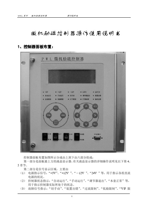
微机励磁控制器操作使用说明书1、控制器面板布置:控制器面板布置如图所示分成由上到下由六部分组成:第一部分是面板最上方的液晶显示器,有关液晶显示器的详细操作说明见以下第4、5章节。
第二部分是信号显示区域,主要由(1)电源指示信号:“+5V”、“+12V ”、“-12V ”、“24V ”等,用于指示各组直流电源的状况。
(2)控制器状态指示:“自动运行”、“手动运行”、“调节器退出”、“本套正常”等,用于指示控制器实际所处于的状态。
(3)故障信号指示:“切手动”、“装置出错”、“过流限制”、“低励限制”、“V/F限制”、“PT熔丝断”、“脉冲出错”等信号,用于指示控制器的故障所在。
其中除“装置出错”外,其余信号皆具有程序自保持功能,即当故障消失后,这些信号不会自动复归,必须人为复归。
“装置出错”是用于指示控制器本身出错的故障信号。
第三部分是控制器操作按钮及指示灯:“置位”按钮、“增磁”按钮、“减磁”按钮及其信号指示,和“信号复归”按钮。
第四部分是液晶显示器键盘操作按钮:包括“∧”键、“∨”键、“<”键、“>”键、“+”键、“-”键、“退出”键、“确认”键。
其中“∧”键、“∨”键用于光标上下移动或屏显前翻后翻;“<”键、“>”键用于光标的左移或右移;“+”键、“-”键用在参数修改时数字量的增加或做试验时各种试验选项的选择等等。
第五部分控制器操作开关及指示灯:“中控”/“就地”开关、“运行”/“退出”开关、“自动”/“手动”开关、“PSS投”/“PSS退”开关及相应的指示灯。
第六部分是串行口:用于同后台机或笔记本电脑通讯,将控制器的参数、试验波形、故障记录、事件记录等数据上传至后台机或笔记本电脑,属于即插即用型,可带电插拔。
上图所示为50MW及以上发电机组励磁调节装置微机励磁控制器面板布置图。
针对25MW及以下发电机组励磁调节装置,如果机组加装PSS则对电力系统影响太小,因此控制器面板布置图没有“PSS投退”开关,其余同上图。
多功能计时器(FMB01DW24)说明书

Product DescriptionMultifunction Multifunction timer with 7functions an d selectable time range from 0.05 sec-onds to 300 hours.48 x 48 mm for front panel mounting an d on 11-pin socket.•Time range 0.05 s to 300 h •Knob selection of time range •Knob adjustable time setting•Knob selection of operating mode (7 functions):Op -delay on operateRb -symmetrical recycler OFF first R -symmetrical recycler ON first Id -double interval Dr -delay on release In -intervalIo -interval on trigger open •Manual start•Gate and reset inputs•Repeatability: ±0.2% on full scale •Output: 8 A DPDT relay•48 x 48 mm housing for front panel mounting •11 pin socket•LED indication for relay status and power supply ONType SelectionMounting Output Plug Supply: 12 to 240 VAC/DC Front or socketDPDT11-pinFMB01DW24Time SpecificationsType FMB01TimersOutput SpecificationsFMB01Function and Time SettingLower left knob:Setting of functionOp-delay on operateRb-symmetrical recycler(OFF first)R-simmetrical recycler(On first)Id-double intervalDr-delay on releaseIn-intervalIo-interval on trigger open Lower right knob:Time unit selector0.1s(0.1 seconds)sec(seconds)10sec(10 seconds)min (minutes)10m (10 minutes)hrs(hours)10h(10 hours)Upper right knob:Time range selector12or 30Centre knob:Time setting on absolutescaleMode of OperationFunction OpDelay on operateThe time period begins as soon as the trigger contact is closed. At the end of the set elay time the relay operates and d oesn’t release until the power sup-ply is disconnected.The trigger contact is invalid while the timer is in opera-tion.Function RbSymmetrical recycler (OFF first)The time period begins as soon as the input contact is closed. The relay is OFF d uring the set d elay period, after this time it operates for the same time period. This sequence continues with equal OFF- and ON- time periods until power supply is interrupted.Function RSymmetrical recycler(ON first)The relay operates and thetime period begins as soonas the input contact isclosed. After the set d elayperiod the relay releases forthe same time period. Thissequence continues withequal ON- and OFF- timeperiods until power supply isinterrupted.Function IdDouble intervalThe relay operates and thetime period begins as soonas the trigger contact isclosed. The relay releases atthe end of this period orwhen the power supply isd isconnecte d. When thetrigger contact is openedthe relay operates again forthe set d elay period. If thetrigger contact is openedbefore the end of the firsttime period the second onebegins; if the trigger contactis closed before the end ofthe second time period therelay keeps ON and the firsttime period begins again.Function DrDelay on releaseThe relay operates as soonas the trigger contact isclose d. The time perio dbegins when the trigger con-tact is opened. The relayreleases at the end of theset d elay time or when thepower supply is disconnect-ed. The relay operates againwhen the input conctact isclosed again. If it is openedbefore the end of the d elaytime the relay keeps ON, anew time period begins assoon as the contact isclosed again.Function InIntevalThe relay operates and thetime period begins as soonas the trigger contact isclosed. The relay releases atthe end of this period orwhen the power supply isd isconnecte d. The relayoperates again when thetrigger contact is close dagain. If the trigger conctactis closed before the end ofthe d elay time, the d eviceresets and a new time peri-od starts.Function IoInteval on trigger openThe relay operates and thetime period begins as soonas the trigger contact isopened. The relay releasesat the end of this period orwhen the power supply isd isconnecte d. The relayoperates again when thetrigger contact is openedagain. If the trigger conctactis opened before the end ofthe d elay time, the d eviceresets and a new time peri-od starts.General SpecificationsFMB01Range and operation mode selectionOperating DiagramsFMB01Wiring DiagramsDimensionsOperating Diagrams (cont.)。
微电脑控制器操作手册

微电脑程序控制器操作手册在使用本控制器之前,请先确定控制器的输入输出范围和输入输出种类与您的需求是相符的。
1.面板说明1.1七段显示器PV :处理值 (process value) ,红色 4 位显示SV :设定值 (setting value) ,绿色 4 位显示1.2LEDOUT1:第一组输出 (Output1) ,绿色灯OUT2:第二组输出 (Output2) ,绿色灯AT:自动演算 (Auto Tuning) ,黄色灯PRO:程式执行中 (Program) ,黄色灯 ----- 只适用于 PFY 系列AL1:第一组警报 (Alarm 1) ,红色灯AL2:第二组警报 (Alarm 2) ,红色灯MAN:输出百分比手动调整 (Manual) ,黄色灯※注意:当发生错误 (Error) 时, MAN 灯会亮,并将输出百分比归零1.3按键SET:设定键 (写入设定值或切换模式 ):移位键 (移动设定位数 ):增加键 (设定值减 1):减少键 (设定值加 1)A/M:自动 (Auto)/ 手动 (Manual) 切换键。
自动:输出百分比由控制器内部演算决定手动:输出百分比由手动调整OUTL( 在 User Level 中)决定2自动演算功能 (Auto tuning)2.2需先将 AT(在 User Level 中)设定为 YES ,启动自动演算功能。
2.3自动演算结束后,控制器内部会自动产生一组新的PID 参数取代原有的 PID 参数。
*自动演算适用于控温不准时,由控制器自行调整PID 参数。
2.4ATVL :自动演算偏移量 (AutoTuning offset Value)SV 减 ATVL 为自动演算设定点,设定 ATVL 可以避免自动演算时,因 PV 值震荡而超过设定点 (Overshoot) 。
例如: SV=200 ℃, ATVL=5 ,则自动演算设定点为195 ℃当自动演算中, PV 值震荡,则是在 195 ℃上下震荡,因此可避免PV 值震荡超过 200℃。
DWYER INSTRUMENTS WE20自动阀门说明书
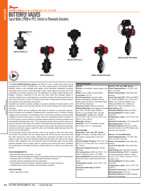
Series WE20 Butterfly Valves are offered in lug or wafer body styles and is equipped with a PTFE or EPDM liner. The most critical aspect of the Series WE20 Butterfly Valves is the cartridge seat design, which alleviates installation problems associated with common “dove tail design” seats. Valve torques are lower and more consistent as the seat dynamics are not dependent on being coupled between two disc and body allow the cartridge design to maintain a tighter disc to seat tolerance, providing a perfect low torque seal each and every time the valve is cycled. The seat to disc seal is independent of flange support and capable of full rated dead end service.Actuators are directly mounted creating a compact assembly for tight spaces. Limit switches are able to be mounted directly to the valves allowing for remote position with either an electric or pneumatic actuator. Electric actuators are available in weatherproof or explosion-proof, a variety of supply voltages and two-position or modulating control. Two-position actuators use the supply voltage to drive the valve open or closed, while the modulating actuator accepts a 4 to 20 mA input for valve positioning. Actuators feature thermal overload protection and permanently lubricated gear train. The pneumatic double acting actuator uses an air supply to drive the valve open and closed. The actuator has two supply ports, with one driving the valve open and the other driving the valve closed. Spring return pneumatic actuators use the air supply to open the valve, and internally loaded springs return the The pneumatic double acting actuator uses an air supply to drive the valve open and closed. The actuator has two supply ports with one driving the valve open and SPECIFICATIONSVALVE Service: Compatible liquids, gases, and steam.Body: 2-way, wafer or lug butterfly.Line Sizes:End Connections: Lug and wafer pattern designed for flanges that are ANSI Class 125 (B16.1) and ANSI Class 150 (B16.5) dimension.Pressure Limits: 225 psi (15.5 bar).Wetted Materials: Body Material: Ductile iron; Disc: 316 SS; Seat: EPDM or PTFE; O-ring: EPDM; Stem: 410 SS.Temperature Limits: Disc: EPDM: -50 to 250°F (-46 to 121°C); PTFE: 0 to 300°F (-18 to 149°C).Bearings: Nylatron.2 to 6˝ 10-position locking hand lever; 8 to 12˝: manual gear.Pneumatic “DA” and “SR” Series DA series is double acting and SR series is spring return (rack and Electric “TD” and “MD” SeriesPower Requirements:VAC or 24 VAC.Power Consumption: manual.Cycle Time (per 90°): 4 s; TD02 and MD02: 20 s; TD03 and MD03: 30 s; TD04 and MD04: 30 s; TD05 and MD05: 30 s; TD06 and MD06: 45 s; TD07 and MD07: 30 s.Duty Rating: Enclosure Rating: Housing Material: aluminum.Temperature Limits: to 60°C).Electrical Connection:Modulating Input: Standard Features: position indicator, and TD models come with two limit switches.Electric “TH and MH SeriesPower Requirements: WE20-CHD00-LEWE20-EDA06-LE WE20-CDA04-WP-AA07WE20-ETD04-LE-AWE20-CDA04-WP-NN08V I D E O O NL IN E415Valves,Butterfly, AutomatedVALVESBUTTERFLY VALVESLug or Wafer, EPDM or PTFE, Electric or Pneumatic ActuatorsSERIES WE20 | W.E. ANDERSON ™ BY DWYER®DWYER INSTRUMENTS, INC. | MODEL CHARTSize Cv (gal/min)Popular Hand Operated Model Price Popular Double ActingPneumatic Model Price PopularSpring Return Pneumatic Model Price NEMA 4X Two- Position Electric (110 VAC) Model Price NEMA 4XModulating Electric(110 VAC) Model Price 2˝2-1/2˝3˝4˝5˝6˝8˝10˝12˝13522030260010221579313653408250WE20-AHD00-WE WE20-BHD00-WE WE20-CHD00-WE WE20-DHD00-WE WE20-EHD00-WE WE20-FHD00-WE WE20-GHD00-WE WE20-HHD00-WE WE20-IHD00-WE $109.00b 123.00b 137.00b 183.00b 229.00b 287.00b 706.00b 972.00b 1419.00b WE20-ADA03-WE WE20-BDA03-WE WE20-CDA04-WE WE20-DDA05-WE WE20-EDA06-WE WE20-FDA07-WE WE20-GDA08-WE WE20-HDA09-WE WE20-IDA11-WE $252.00b 270.00b 309.00b 385.00b 485.00b 586.00b 1024.00b 1507.00b 2016.00bWE20-ASR04-WE WE20-BSR04-WE WE20-CSR06-WE WE20-DSR07-WE WE20-ESR08-WE WE20-FSR09-WE WE20-GSR10-WE WE20-HSR11-WE WE20-ISR11-WE$291.00b 309.00b 384.00b 474.00b 637.00b 943.00b 1465.00b 2351.00b 2447.00bWE20-ATD02-WE-A WE20-BTD02-WE-A WE20-CTD02-WE-A WE20-DTD03-WE-A WE20-ETD04-WE-A WE20-FTD04-WE-A WE20-GTD05-WE-A WE20-HTD06-WE-A WE20-ITD07-WE-A$623.00b 641.00b 660.00b 989.00b 1253.00b 1324.00b 1842.00b 2563.00b 2814.00b WE20-AMD02-WE-A WE20-BMD02-WE-A WE20-CMD02-WE-A WE20-DMD03-WE-A WE20-EMD04-WE-A WE20-FMD04-WE-A WE20-GMD05-WE-A WE20-HMD06-WE-A WE20-IMD07-WE-A$1130.00b 1152.00b 1167.00b 1593.00b 1858.00b 1930.00b 2510.00b 3260.00b 3382.00bb Items are subject to Schedule B discounts.MODEL CHART - HAND OPERATED & PNEUMATIC ACTUATOR Example WE20-BSR04-WE -A A 00WE20-BSR04-WE-AA00Price Series WE20Butterfly valve -Size and Actuator AHD00BHD00CHD00DHD00EHD00FHD00GHD00HHD00IHD00ADA03BDA03CDA04DDA05EDA06FDA07GDA08HDA09IDA11ASR04BSR04CSR06DSR07ESR08FSR09GSR10HSR11ISR112˝ hand operated 2-1/2˝ hand operated 3˝ hand operated 4˝ hand operated 5˝ hand operated 6˝ hand operated 8˝ hand operated 10˝ hand operated 12˝ hand operated 2˝ double acting 2-1/2˝ double acting 3˝ double acting 4˝ double acting 5˝ double acting 6˝ double acting 8˝ double acting 10˝ double acting 12˝ double acting 2˝ spring return 2-1/2˝ spring return 3˝ spring return 4˝ spring return 5˝ spring return 6˝ spring return 8˝ spring return 10˝ spring return 12˝ spring return $109.00b 123.00b137.00b 183.00b 229.00b 287.00b 706.00b 972.00b 1419.00b 252.00b 270.00b 309.00b 385.00b 485.00b 586.00b 1024.00b 1507.00b 2016.00b 291.00b 309.00b 384.00b 474.00b 637.00b 943.00b 1465.00b 2351.00b 2447.00bBody Type /Liner WE WP LE LP Wafer-EPDM Wafer-PTFE Lug-EPDM Lug-PTFE -+53.50b +8.60b+62.00bSolenoid N A No solenoid NEMA 4X NAMUR solenoid -+53.50b Solenoid Voltage N A B C D E No solenoid 120 VAC 220 VAC 24 VAC 24 VDC 12 VDC ------Positioner and Switches 000102030406070809None 42AD0 exp limit switch 45VD0 exp position transmitter 42AD0-B ATEX limit switch 42AD0-IE IECEX limit switch QV-210101 poly limit switch VPS and P1 prox switch 265ER-D5 positioner 285ER-D5 smart positioner -+245.00b +558.00b+343.00b +340.00b +153.00b +219.00b +679.00b +1592.00bOptions NO Fail open spring return actuator -b Items are subject to Schedule B discounts.MODEL CHART - ELECTRIC ACTUATORExample WE20-DMH05-WE -A WE20-DMH05-WE-A Price Series WE20Butterfly valve -Size and Actuator ATD02BTD02CTD02DTD03ETD04FTD04GTD05HTD06ITD07AMD02BMD02CMD02DMD03EMD04FMD04GMD05HMD06IMD07ATH03BTH03CTH05DTH05ETH06FTH08GTH09HTH10ITH11AMH03BMH03CMH05DMH05EMH06FMH08GMH09HMH10IMH112˝ NEMA 4X two-position 2-1/2˝ NEMA 4X two-position3˝ NEMA 4X two-position 4˝ NEMA 4X two-position 5˝ NEMA 4X two-position 6˝ NEMA 4X two-position 8˝ NEMA 4X two-position 10˝ NEMA 4X two-position 12˝ NEMA 4X two-position 2˝ NEMA 4X modulating 2-1/2˝ NEMA 4X modulating 3˝ NEMA 4X modulating 4˝ NEMA 4X modulating 5˝ NEMA 4X modulating 6˝ NEMA 4X modulating 8˝ NEMA 4X modulating 10˝ NEMA 4X modulating 12˝ NEMA 4X modulating 2˝ exp two-position 2-1/2˝ exp two-position 3˝ exp two-position 4˝ exp two-position 5˝ exp two-position 6˝ exp two-position 8˝ exp two-position 10˝ exp two-position 12˝ exp two-position 2˝ exp electric modulating 2-1/2˝ exp electric modulating 3˝ exp electric modulating 4˝ exp electric modulating 5˝ exp electric modulating 6˝ exp electric modulating 8˝ exp electric modulating 10˝ exp electric modulating 12˝ exp electric modulating$623.00b 641.00b 660.00b 989.00b 1253.00b 1324.00b 1842.00b 2563.00b 2814.00b 1130.00b 1152.00b 1167.00b 1593.00b 1858.00b 1930.00b 2510.00b 3260.00b 3382.00b 623.00b 641.00b 2635.00b 2696.00b 3031.00b 3328.00b 3843.00b 5914.00b 6575.00b 1130.00b 1152.00b 3912.00b 3974.00b 4308.00b 4330.00b 4865.00b 7025.00b 7901.00bMaterial/Liner WE WP LE LP Wafer-EPDM Wafer-PTFELug-EPDM Lug-PTFE-+53.50b +8.60b +62.00bActuator Voltage A B C D 110 VAC 220 VAC24 VAC 24 VDC--+75.00b +75.00bb Items are subject to Schedule B discounts.ACCESSORIES Model Description Price AFR4VB-01Air filter regulator 0 to 120 psi Volume booster $72.00b 182.00b b Items are subject to Schedule B discounts.。
特菲尔操作手册
图1-1控制器主面板图
第1章操作 继续
操作按键
按键名称
按键功能
【火警确认】
火警事件确认,当有新火警事件时,按下【火警确认】小于1秒,确认一个事件,长按全部确认,全部确认后控制器中的蜂鸣器报警音响被禁止,报警指示灯停止闪烁,详见1.4.1章节。
【预警确认】
预警事件确认,当有新预警事件时,按下【预警确认】确认事件,全部确认后控制器中的蜂鸣器报警音响被禁止,报警指示灯停止闪烁,详见1.4.2章节。
进入步行测试画面后,按下控制器面板上的【启动】键,进入步行测试。步行测试启动后,系统将转入测试状态,表现如下;
联动关系将不再启动;
回路探测器报警不需要关联;
如果设置了火警延时,回路首个火警不等待;
回路探测器报火警每持续10秒,重复报告一次,主机火警显示时间将会更新;
回路将不会启动模块;
系统不发送本机火警、故障到CRT;
1.4.2
预警事件有以下几种情况:
探测器探测到在火灾初期的轻微烟雾浓度时,经控制器判断后,报出预警信息。
- 1、下载文档前请自行甄别文档内容的完整性,平台不提供额外的编辑、内容补充、找答案等附加服务。
- 2、"仅部分预览"的文档,不可在线预览部分如存在完整性等问题,可反馈申请退款(可完整预览的文档不适用该条件!)。
- 3、如文档侵犯您的权益,请联系客服反馈,我们会尽快为您处理(人工客服工作时间:9:00-18:30)。
VERSION:A
电磁脉冲控制器使用说明书
Suitable for DWPC-20-DC24
ZhouPan technology
2015/5/6 Wednesday
产品十大特色:
1、微电脑自动控制,智能定时、稳定可靠;
2、具有20路脉冲阀控制能力,更好的适应现场需求;
3、脉冲宽度、脉冲间隔、周期间隔、输出路数自由设置,方便快捷;
4、设备运行/停机按键切换,方便现场操作和检查;
5、设置功能,按键快速调整参数,节省操作时间;
6、卡扣式安装,可方便安装在仪表面板上;
7、具有外部短路保护功能,避免因线路短路造成设备损坏;
8、具有过压、欠压保护能力,设备运行更加可靠;
9、宽电压输入(85-220)V均可,尤其适应现场电压不稳的情况;
10、后端大电流隔离接线端子,使拆卸、更换以及检测更加方便。
⏹概述
脉冲控制仪是脉冲式布袋除尘器喷吹清灰系统的主要控制装置,它的输出信号控制脉冲电阀,使喷吹压缩空气对过滤袋循环清灰,除尘器的阻力保持在设置范围内,以保证除尘器的处理能力和收尘效率。
本产品是自主开发的新一代产品,采用可编辑程序微电脑控制芯片,电路采用抗高干扰设计,具有短路、过压保护功能,并且使用方便。
术语定义:
脉冲宽度:控制仪输出一个电信号控制脉冲阀开启持续的时间(秒)。
脉冲间隔:控制仪输出控制两个脉冲阀开启的间隔时间(秒)。
周期间隔:控制仪控制所有脉冲阀开启一次后的停歇时间(秒)。
输出路数:控制仪控制脉冲阀的个数。
⏹技术指标
1、待机功耗:0.1W
2、输入电压范围:(85-220)V AC
3、额定电压:220VAC
4、额定输出电压:24VDC
5、额定输出电流: 1.2A
6、脉冲间隔设定范围:0.1-9999秒
7、脉冲宽度设定范围:0.1-9999秒
8、周期间隔设定范围:0.1-9999秒
9、输出路数:20路(可根据需要配置1-20路)
10、外形尺寸:80*160*80mm
11、安装方式:柜装、卡扣式
12、使用环境:-10℃--+60℃,干燥避开强电磁场,注意防尘。
⏹接线方式
接线柱L、N接入220VAC,COM端为公共端接入电磁阀线圈一端,另一端依次接1、2、3 ......。
备注:电磁阀最多可接入20路,当现场实际路数小于20时,需从1号起依次顺序接线。
禁止一路接入2个或以上的电磁阀。
⏹操作设置说明
开机/停机操作:
上电后仪表进入运行状态,自动按照设定参数依次循环打开脉冲阀。
运行状态时“电源(POWER)指示灯”和“运行(WORK)指示灯”亮。
面板上方数码管显示时间,下方数码管显示当前工作阀组编号。
“脉冲宽度”“脉冲间隔”“周期间隔”指示灯指示阀组工作状态。
在运行状态时,按下“开关”按键,系统进入停机状态,外部所有脉冲阀均关闭,计时时间暂停。
此时“运行(WORK)指示灯”灭。
再次按下“开关”按键则恢复运行状态,计时恢复。
设置操作
系统运行状态时按下“设置”键,控制器关闭所有脉冲阀并进入设置状态。
“设置(SET)指示灯”亮。
每按下一次“设置(SET)键”,将依次设置脉冲宽度、脉冲间隔、周期间隔、输出路数等参数。
对应指示灯会依次亮起。
在对应指示灯亮起时按下“加(ADD)”、“减(REDUCE)”按键即可修改相对应的参数值(单位/秒)。
修改完输出路数参数后再按设置键(SET),各参数灯灭,运行指示灯亮,立即进入运行状态。
注:为方便客户调节参数值变化(0.1—9999.9秒)较大的情况,用户按下“加(ADD)”、“减(REDUCE)”按键时间越长,参数值变化的速率也就越快。
例如按一下按键增加或减少0.1S,而按住3秒以上则按照1S的速度增加或减少。
方便快速调整到客户指定的数值。
⏹使用注意与故障排除
1、控制仪安装使用后,应有专人负责,每天检查运行情况,发现故障及时排除。
2、控制仪接上电源,指示灯不亮,应检查接线端子上的电源线是否松动,保险丝是否正常。
3、控制仪显示正常,某一脉冲阀不动作,检查对应接线和端子是否损坏。
4、控制仪显示正常,两脉冲阀同时动作,检查控制仪有无碰撞现象或连电。
5、控制仪显示正常,电磁阀均不动作,检查输出线端子的公共端是否接触可靠。
6、数码管闪烁,检查保险丝是否松动,电源是否正常。
7、该仪表具有过流、过压、欠压保护功能,在发生短路(过流)、过压情况下会立即断电后重启,直到故障清除。
附:
☞1、禁止接入和操作说明不一致的电源和负载。
2、非专业人员禁止拆卸和自行修改电路,否则后果自负。
3、产品售出一月内出现任何问题,负责免费换新,一年内出现任何问题,负责免费维修。