3362R202中文资料
BNS 36-02 10ZG-R 商品说明书

DATASHEETDataOrdering dataProduct type description BNS 36-02/10ZG-R101216952 Article number (ordernumber)EAN (European Article4030661412320 Number)27-27-24-02eCl@ss number, version11.0eCl@ss number, version27-27-24-029.0ETIM number, version 7.0EC002544ETIM number, version 6.0EC002544Approvals - StandardsCertificates TÜVBGcULusGeneral dataStandards BG-GS-ET-14EN IEC 60947-5-3Coding level according toEN ISO 14119LowWorking principle Magnetic driveInstallation conditions(mechanical)quasi-flushEnclosure material Glass-fibre, reinforced thermoplastic Gross weight120 gGeneral data - FeaturesIntegral systemdiagnostics, statusYesNumber of normallyclosed (NC)2Number of normally open(NO)1Number of safetycontacts2Number of cable wires6Safety classificationStandards EN ISO 13849-1Mission time20 Year(s)Safety classification - Safety outputsB10D Normally-closedcontact (NC)25,000,000 OperationsMechanical dataActuating element MagnetDirection of motion Head-on to the active surfaceMechanical data - Switching distances according EN IEC 60947-5-3Note (Switching distance Sn)Axial misalignment, a horizontal and vertical misalignment of the safety sensor and the actuator are tolerated. The possible misalignment depends on the distance of the active surfaces of the sensor and the actuator. The sensor remains active within the tolerance range.Assured switchingdistance "ON" Sao6 mmAssured switchingdistance "OFF" Sar17 mmMechanical data - Connection technique Length of cable 1 mTermination CableWire cross-section0.25 mm2Wire cross-section23 AWGMaterial of the CablemantlePVCMechanical data - DimensionsLength of sensor13 mmWidth of sensor88 mmHeight of sensor25 mmAmbient conditionsDegree of protection IP67Ambient temperature-25 ... +70 °CStorage and transporttemperature, minimum-25 °CStorage and transporttemperature, maximum+70 °CResistance to vibrations10 … 55 Hz, amplitude 1 mm Restistance to shock30 g / 11 msElectrical dataSwitching current,maximum0.01 ASwitching capacity,maximum0.2 WSwitching frequency,maximum5 HzStatus indicationNote (Integral SystemDiagnostics, status )The LED is illuminated when the guard is closed.Scope of deliveryScope of delivery Actuator must be ordered separately.AccessoryRecommendation(actuator)BPS 36-2Recommended safety switchgear SRB-E-301ST SRB-E-201LCNoteNote (General)Contact symbols shown for the closed condition of the guard device.The contact configuration for versions with or without LED is identical.Ordering codeProduct type description:BNS 36-(1)(2)Z(3)-(4)-(5)(1)11 1 NO contacts/1 NC contact02 2 NC contact(2)without with diagnostic output/01 1 NC contact10 1 NO contact(3)without without LED switching conditions displayG with LED switching conditions display(4)without Pre-wired cableST with connector(5)L Door hinge on left-hand sideR Door hinge on right-hand side(6)2750Version with extended switching distance (incombination with actuator) BPS 36-1-2750 or BPS 36-2-2750)DocumentsOperating instructions and Declaration of conformityBNS 36-02/10(291.7 kB, 10.05.2019, Revision C)UL CertificateBNS 36(385.0 kB, 01.08.2019)SISTEMA-VDMA library(659.5 kB, 23.03.2023)PicturesProduct picture (catalogue individual photo)ID: kbns3f35| 205.0 kB | .jpg | 352.778 x 92.428 mm - 1000 x 262 px - 72 dpi| 16.0 kB | .png | 74.083 x 19.403 mm - 210 x 55 px - 72 dpiDimensional drawing basic componentID: 1bns3g13| 25.5 kB | .cdr || 3.2 kB | .png | 74.083 x 51.506 mm - 210 x 146 px - 72 dpi| 62.4 kB | .jpg | 352.778 x 245.181 mm - 1000 x 695 px - 72 dpiDiagramID: kbns2k04| 19.5 kB | .cdr || 87.7 kB | .jpg | 352.778 x 85.372 mm - 1000 x 242 px - 72 dpi| 3.9 kB | .png | 74.083 x 17.992 mm - 210 x 51 px - 72 dpiCharacteristic curveID: kbns3a29| 165.7 kB | .jpg | 352.778 x 215.9 mm - 1000 x 612 px - 72 dpi| 110.2 kB | .png | 50.038 x 30.649 mm - 591 x 362 px - 300 dpi| 165.7 kB | .jpg | 352.778 x 215.9 mm - 1000 x 612 px - 72 dpiCharacteristic curveID: kbns3a30| 16.9 kB | .png | 74.083 x 45.156 mm - 210 x 128 px - 72 dpi| 164.2 kB | .jpg | 352.778 x 215.547 mm - 1000 x 611 px - 72 dpiOperating principle| 20.2 kB | .cdr || 52.3 kB | .jpg | 352.778 x 250.825 mm - 1000 x 711 px - 72 dpi| 1.8 kB | .png | 74.083 x 52.564 mm - 210 x 149 px - 72 dpiSystem componentsControl-ModulPlug-in screw terminals with codingSTOP 0 Function1 oder 2-channel controlStart button / Auto-start2 Safety outputs 2 A1 Signalling outputPlug-in screw terminals with codingSTOP 0 FunctionMonitoring of 4 sensorsStart button / Auto-start2 Safety outputs4 Signalling outputsPlug-in screw terminals with codingSTOP 0 Function1 oder 2-channel controlStart button / Auto-start1 Auxiliary contact3 safety contactsK.A. Schmersal GmbH & Co. KG, Möddinghofe 30, 42279 WuppertalThe details and data referred to have been carefully checked. Images may diverge from original. Further technical data can be found in the manual. Technical amendments and errors possible.Generated on: 25/07/2023, 01:50。
UD Trucks产品手册说明书

Full Range Guide 20221935Model OverviewIndustry Segmentation ConstructionDistribution WastePK 18 280 PD 25 280 CW 25 360 CW 26 390 GW 26 460 CG 30 360 CG 32 420 GK 17 420PK 18 280PD 25 280CD 25 360GW 26 460GK 17 420CG 30 360PK 18 280CW 25 360CW 26 390CG 30 360CG 32 420Do more with every minute in the Croner:UD Truck’s medium duty solution.Croner is named after Chronos, the god of time inGreek mythology, because it saves you time – and thatsaves you money. It means more time on the road andless time in the workshop.With a comfortable cab, high torque UD engine andin-built fuel efficiency, Croner maximises productivityand minimises downtime.PRODUCTIVITY4x2 and 6x2 configurations. Wheelbase, rear-axleratio and suspension optionsUPTIME SUPPORTGenuine service, parts, roadside assistance, drivertraining and telematicsPRODUCT UPTIMERobust component design and a high tensilesteel chassisFUEL EFFICIENCYGH8E engine with 1,050Nm of torque and UD’son-board fuel coachSAFETYAnti-lock Braking System (ABS), ElectronicBrakeforce Distribution (EBD), driver's airbag,digital reverse camera and seatbelt pretensioner asstandard.DRIVER EFFICIENCYAllison automatic transmission and ergonomiccab designWith innovation that putspeople first, the Quon offersa host of industry-leadingfeatures.Easier to use, smoother to driveCompletely re-designed cabin provides greater driver comfort. ESCOT-VIautomated manual transmission is the next evolution in unparalleled operability.The robust Allison automatic transmission also offers a double overdrive andadvanced shifting capability for on or off road conditions. These innovationscontribute to a comfortable environment for drivers.Safer and more dependableSafe driving is easier if the truck can predict potential dangers and warn the driver. The Quon features advanced technologies to enable this.• Disc brakes on all wheels• Electronic stability control• Traffic eye brake• Lane departure warning• Brake blending• Driver alert system (optional)• Automatic hill start assist• Adaptive Cruise Control (ESCOT VI only)Better productivity, better efficiencyWe’ve reduced the weight of all models. This improves load handling and suspension. As a result of this lower tare weight, carrying capacities have increased on these mdoels.Reliable uptime for greater peace of mindThe Quon offers comprehensive aftersales services, such as genuine service, genuine parts, UD-TRUST service agreements, and UD telematics. This combination provides an unprecedented level of uptime, as well as the comfort of predictable costs and the peace of mind that your UD is receiving the best parts and service available.Cleaner and more powerfulRefinements to the driveline have achieved a high level of fuel efficiency that contributes savings directly to the bottom line. The fuel efficient, powerful, and clean GH11 and GH8 engines comply with stringent pPNLT Emissions Standards that exceed Euro 6 emission requirements.The powerful range of Quon trucks offers a unique combination of high power to weight ratio, 8 and 11 litre engines, UD’s world-class AMT (Automated Manual Transmission) the ESCOT VI, as well as the popular Allison 6-speed automatic. Coupled with a full safety package, the Quon delivers increased fuel economy, increased efficiency, reduced emissions and less driver fatigue without compromising on performance. At UD Trucks we live for ultimate dependability. We go the extra mile for you in everything we do, which in turn enables you and your fleet to go the extra distance. From service and parts to on-road support, driver training and telematics, UD Extra Mile Support is our complete solution that you can rely on to keep your truck running.UD Extra Mile Supportprofitability by maximising vehicleuptime and fuel efficiency.Because every part of your truckmatters. Designed and tested toprovide the highest quality anddurability, UD Genuine Partsincrease uptime and loweroperating costs. Not to mentionyou’ll also get 24 months warrantyon all genuine parts as well as thelabour when fitted in a UDworkshop.Optimised ServicePlanningWe work with you to create afree Service Schedule. This ServiceSchedule is tailored to your truckand is designed to give your truckexactly the maintenance it needs -no more and no less.UD Trucks Financial Servicesdelivers a full range of productsand services available directlythrough your UD Trucks dealernetwork. You’ll get a finance orlease solution that’s tailored toyour needs from the same placewhere you purchase and serviceyour truck.AgreementsUD Trust Service Agreementsare tailored specifically to yourbusiness and designed toeffectively lower the total costof ownership of your trucks.You deserve peace of mind. If abreakdown brings your truck toan unexpected standstill, helpUD Trust Basic – Preventative maintenancedelivered during routine servicesUD Trust Extra – Includes all that is included inthe Basic Program as well as repairs to brakecomponents.UD Trust Ultimate – The most comprehensiveof our Service Agreements, covering all that isincluded in the Basic and Extra Programs plusrepairs to electrical, engine, driveline, brakingand steering systems./australia The specifications in this catalogue are subject to change without notification. The specifications, colors, and other details of the actual vehicles might vary slightly. The addition of optional features could change the weight of the final product. For more information, please contact your nearest UD Trucks dealer. This catalogue is current as of May 2022.UD Trucks Australia。
轮胎行业术语中英文对照教材

轮胎行业术语中英文对照目录1.轮胎基本用语 (1)2.轮胎安全 (6)3.制品检查、制品试验 (27)4.原材料 (31)5.材料试验/中间制品试验 (36)6.制造工程用语 (43)1.轮胎基本用语2.轮胎安全Information胎边标示LabelingRequirements轿车胎、备胎或10000磅以下Light V ehicle用辐射层轮胎须以永久模印方式固定在两侧胎边者:●规格(标称尺度)●最大允许充气压力●最大荷重●胎边部帘布及胎面部之帘布、环带、束带等所使用之cord材质●胎边部帘布及胎面部之帘布、环带、束带等之所使用实际层数。
●依实际适用而标示”TUBELESS”或”TUBE TYPE”●如为辐射层轮胎须标示”RADIAL”●如为泥雪地适用需标示”M+S”或”M&S”或”M/S”以上除特定者外所有字高>2mm、字深>0.38mm,且至少一侧位置须在最大断宽~胎唇之间,并不得被轮圈凸缘所遮盖住。
●制造厂或商标●轮胎识别代号TIN:如轮胎有特定装着位置者(如白边或单导向轮胎)于装着之外侧边须标示全部之TIN(轮胎识别码:工厂代号、规格代号、轮胎型式代号、制造年周序号),而另一侧可标示全部或局部之TIN(但两侧皆须有制造年周序号)。
如无特定装着位置者,一侧须标示全部之TIN,而另一侧可标示全部或局部之TIN(但两侧皆须有制造年周序号)。
TIN字高>6.5mm字深0.6~1.0mm字高大小及位置如图四:图四●TWI胎面磨耗指示记号及平台1.6mm,全圆周约等间配置至少6处。
●如为备胎则标示”TEMORARY TIRE USE ONLY” ;且字高>13mm●如最大充气压力为420kPa或60psi则标示”INFALTED TO 420kPa(60PSI)” ;且字高>13mm●安全警语(Safety Warning )----非强制性●转动方向或装胎位置(如为单导向或非对称花纹时)。
2SJ356-T2中文资料
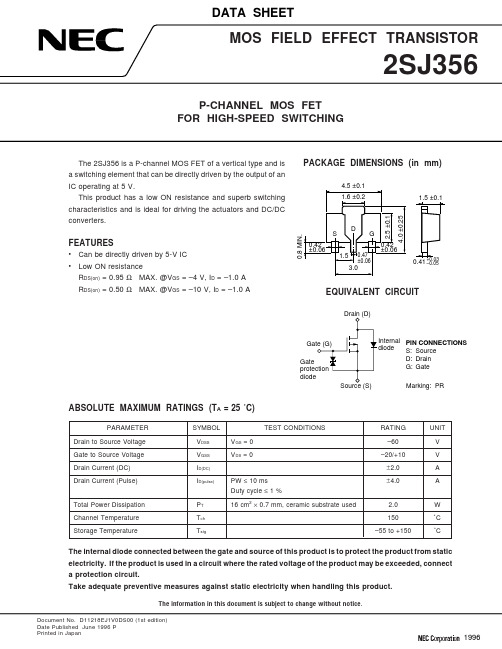
Document No. D11218EJ1V0DS00 (1st edition)Date Published June 1996 PPrinted in Japan19962TYPICAL CHARACTERISTICS (T A = 25 ˚C)DERATING FACTOR OF FORWARD BIAS SAFE OPERATING AREAd T - De r a t i n g F a c t o r -%2510080604020T A - Ambient Temperature - ˚CFORWARD BIAS SAFE OPERATING AREAI D - D r a i n C u r r e n t - A–0.5–10V DS - Drain to Source Voltage - V5075100125150–5–2–1–0.5–0.2–0.1–0.05–1–100–2–5–10–20–502SJ3563DRAIN TO SOURCE ON-STATE RESISTANCE vs.DRAIN CURRENT R D S (o n ) - D r a i n t o S o u r c e O n -S t a t e R e s i s t a n c e - Ω–0.00110.80.60.40.2I D - Drain Current - ADRAIN TO SOURCE ON-STATE RESISTANCE vs.GATE TO SOURCE VOLTAGE R D S (o n ) - D r a i n t o S o u r c e O n -S t a t e R e s i s t a n c e - Ω010.80.60.40.2V GS - Gate to Source Voltage - V–10–0.01–0.1–1–20–2–4–6–8–10–12–14–16–18DRAIN CURRENT vs.DRAIN TO SOURCE VOLTAGEI D - D r a i n C u r r e n t - A–5V DS - Drain to Source Voltage - V TRANSFER CHARACTERISTICS I D - D r a i n C u r r e n t - A–1–10V GS - Gate to Source Voltage - VFORWARD TRANSFER ADMITTANCE vs.DRAIN CURRENT |y f s | - F o r w a r d T r a n s f e r A d m i t t a n c e - S–0.000110I D - Drain Current - ADRAIN TO SOURCE ON-STATE RESISTANCE vs.DRAIN CURRENT R D S (o n ) - D r a i n t o S o u r c e O n -S t a t e R e s i s t a n c e - Ω–0.0011.5I D - Drain Current - A–1–2–3–4–5–4–3–2–1–2–3–4–1–0.1–0.01–0.001–0.0001–0.0000110.10.010.001–0.001–0.01–0.1–110.5–0.01–0.1–1–104TRANSIENT THERMAL RESISTANCE vs. PULSE WIDTHrth(j-a)-TransientThermalResistance-˚C/W1 m1 000100101PW - Pulse Width - s10 m100 m110100Single pulseUsing ceramic substrate of7.5 cm2× 0.7 mmSOURCE TO DRAIN DIODEFORWARD VOLTAGEISD-DiodeForwardCurrent-A–0.2–10–1–0.1–0.01–0.001–0.0001V SD - Source to Drain Voltage - VCAPACITANCE vs.DRAIN TO SOURCE VOLTAGECiss,Coss,Crss-Capacitance-pF–110 0001 00010010V DS - Drain to Source Voltage - V SWITCHING CHARACTERISTICStd(on),tr,td(off),tf-SwitchingTime-ns1 00010010I D - Drain Current - AREVERSE RECOVERY TIME vs.DIODE FORWARD CURRENTtrr-ReverseRecoveryTime-ns–0.051 00010010I F - Diode Forward Current -A–1.2–0.4–0.6–0.8–1.0V GS = 0Pulsed–10–100–1–10–10–0.1–0.5–1–5V GS = 0di/dt = 50 A/ sµREFERENCEDocument Name Document No.NEC semiconductor device reliability/quality control system TEI-1202Quality grade on NEC semiconductor devices IEI-1209 Semiconductor device mounting technology manual C10535EGuide to quality assurance for semiconductor devices MEI-1202 Semiconductor selection guide X10679E5[MEMO]No part of this document may be copied or reproduced in any form or by any means without the prior written consent of NEC Corporation. NEC Corporation assumes no responsibility for any errors which may appear in this document.NEC Corporation does not assume any liability for infringement of patents, copyrights or other intellectual property rights of third parties by or arising from use of a device described herein or any other liability arising from use of such device. No license, either express, implied or otherwise, is granted under any patents, copyrights or other intellectual property rights of NEC Corporation or others.While NEC Corporation has been making continuous effort to enhance the reliability of its semiconductor devices, the possibility of defects cannot be eliminated entirely. To minimize risks of damage or injury to persons or property arising from a defect in an NEC semiconductor device, customer must incorporate sufficient safety measures in its design, such as redundancy, fire-containment, and anti-failure features.NEC devices are classified into the following three quality grades:“Standard“, “Special“, and “Specific“. The Specific quality grade applies only to devices developed based ona customer designated “quality assurance program“ for a specific application. The recommended applicationsof a device depend on its quality grade, as indicated below. Customers must check the quality grade of each device before using it in a particular application.Standard:Computers, office equipment, communications equipment, test and measurement equipment, audio and visual equipment, home electronic appliances, machine tools, personal electronicequipment and industrial robotsSpecial:Transportation equipment (automobiles, trains, ships, etc.), traffic control systems, anti-disaster systems, anti-crime systems, safety equipment and medical equipment (not specifically designedfor life support)Specific:Aircrafts, aerospace equipment, submersible repeaters, nuclear reactor control systems, life support systems or medical equipment for life support, etc.The quality grade of NEC devices in “Standard“ unless otherwise specified in NEC's Data Sheets or Data Books.If customers intend to use NEC devices for applications other than those specified for Standard quality grade, they should contact NEC Sales Representative in advance.Anti-radioactive design is not implemented in this product.M4 94.11。
摩托车轮胎规格尺寸
摩托车轮胎系列Series of motorcycle tyresGB/T 2983-1997 eqvISO 4249-1:1985ISO 4249-2:1990 ISO 5751-1:1994 ISO 5751-2:1994ISO 5751-3:1994 ISO 5995-1:1982 ISO 6054-1:1994 代替 GB/T 2983-91国家技术监督局 1997-10-14 批准 1998-04-01实施前言本标准是根据国际标准ISO 4249-1:1985《摩托车轮胎和轮辋(代号表示系列)──第1部分:轮胎》、ISO 4249-2:1990《摩托车轮胎和轮辋(代号表示系列)──第2部分:轮胎额定负荷》、ISO 5751-1:1994《摩托车轮胎和轮辋(公制系列)──第1部分:设计准则》、ISO 5751-2:1994《摩托车轮胎和轮辋(公制系列)──第2部分:轮胎尺寸及负荷能力》、ISO 5751-3:1994《摩托车轮胎和轮辋(公制系列)──第3部分:配套轮辋轮廓范围》、ISO 5995-1:1982《轻便型摩托车轮胎和轮辋──第一部分:轮胎》ISO 6054-1:1994《摩托车轮胎和轮辋(直径代号4至12)小轮径──第1部分:轮胎》进行修订的。
同时参照日本JIS D 4203-1991《摩托车轮胎系列》标准,在主要技术内容上等效采用ISO标准。
本标准与前版标准主要不同之点是将使用条件特征与公制系列摩托车轮胎的胎面型式作附录处理,并对公制系列摩托车轮胎的规格和尺寸依据ISO标准做了大量补充,增加了轮胎断面名义高宽比为50、55、60、70系列轮胎的规定,使其规格系列更加完善,有利于与国际接轨,促进我国摩托车及摩托车轮胎工业的发展。
本标准从生效之日起,同时代替GB 2983-91。
本标准将使用条件特征编入附录A(标准的附录),公制系列摩托车轮胎的胎面型式编入附录B(提示的附录)。
轮胎行业术语中英文对照

轮胎行业术语中英文对照(总44页)-CAL-FENGHAI.-(YICAI)-Company One1-CAL-本页仅作为文档封面,使用请直接删除轮胎行业术语中英文对照目录1.轮胎基本用语 (1)2.轮胎安全 (5)3.制品检查、制品试验 (17)4.原材料 (22)5.材料试验/中间制品试验 (27)6.制造工程用语 (34)1.轮胎基本用语2.轮胎安全●压座型式及速度:图六为适用轿车胎;图七为适用备胎(充气420kPa以上),压座速度=50mm/min直至轮胎之胎唇脱座或已达最小脱座力要求为止,全圆周约等间四位置测试。
●压座距离设定:图六图七表一●最小脱座力: 轿车胎备胎(420kPa )最小脱座力LBS(kg ) 公称断宽胎边标示最大荷重(kg )SW 160 LOAD 399 1500(680) 160≦SW205 399≦LOAD635 2000(907) SW ≧205 LOAD ≧635 2500(1134)破坏能Breaking Energy (Plunger Test ;Tire Strength )● FMVSS571 109;119及JIS 、CNS 、GB 等规定,用半球端圆柱棒刺入胎面胶块,量测帘布破坏或刺达轮圈时之力F 与距离P ,用以检测轮胎之破坏能W=FxP/2● 各轮胎类别使用之半球端圆柱棒(柱塞)直径轮胎类别柱塞直径(mm )机车胎(MC 、SC ) 8 轿车胎(PC ) 19 轻卡车胎(LT )轮胎ID ≦12”者 (但机车胎除外)上述以外之轮胎TUBELSSID ≦17.5”ID >17.5”LR≦12PR 32 LR >12PR38 TUBE TYPELR≦12PR32 LR >12PR38●充气压力:轿车胎及备胎参见表一;其它轮胎依胎边标示最大允许充气压力● 柱塞于胎面中心(或靠近)之花纹胶块以速度50mm/min 刺入;全圆周约等间距五处测试(ID ≦12”者三处)。
佳通轮胎产品手册

强力尼龙斜交轮胎佳通轮胎产品手册2010斜交胎细分市场卡客车轮胎R17L05R18G212TR120R17公路型TR120纵向曲折的胎面花纹设计加强的胎体结构设计加宽的轮胎冠宽设计提高轮胎的抗沟裂性能提高轮胎综合性能提高轮胎耐磨性能注: SUPER 表示加强层级。
注 :* 表示即将上市。
R18公路型11.00-2018PR 153/148F 8.0 3650/3150910/84016.012.00-2018PR154/150F8.53730/3270810/74016.910.00-2016PR 146/142G 7.5 3000/2630810/74021.411.00-2018PR 153/148F 8.0 3650/3150910/84022.312.00-2018PR154/150F8.53730/3270810/74023.3强力尼龙斜交轮胎卡车轮胎C08TC160TC161G218G216工矿型G218技术特点优势采用坏路专用胎面配方提高胎面耐刺扎、耐切割、耐撕裂性能注:*表示即将上市。
规格层级负荷指数单胎/双胎速度级别标准轮辋额定负荷(kg) 单胎/双胎额定气压(kPa)单胎/双胎沟深(mm)9.00-20 *16PR 145/140B 7.0 2900/2500880/81022.010.00-20 *18PR 150/145B 7.5 3350/2900910/84025.011.00-20 *18PR 153/148B 8.0 3650/3150910/84027.012.00-20 *20PR156/151B8.54000/3450880/81028.5工矿型强力尼龙斜交轮胎10.00-2016PR 146/142J 7.5 3000/2630810/74017.611.00-2018PR 153/148F 8.0 3650/3150910/84018.112.00-2018PR154/150F8.53730/3270810/74018.8G216强力尼龙斜交轮胎7.50-16 LT 14PRSUPER 122/118L 6.00G 1500/1320730/73017.48.25-16 LT16PR128/124L6.50H1800/1600730/73021.5注: SUPER 表示加强层级。
uscar-2 rev 6_february 2013(中文版)

汽车电连接器系统性能规范SAE/USCAR-2第6版2013.2ISBN:978-0-7680-7998-2SAE/USCAR-2第6版颁布日期1997年8月修订日期2013年2月汽车电连接器系统的性能规范目录1.范围 (3)2.试验顺序 (3)3.参考文档 (3)3.1文件的层次 (3)3.2零件图 (4)3.3产品设计规范 (4)3.4测试要求/指令 (4)3.4.1样品,测试类型,和特殊测试 (4)3.4.2测试要求/指令说明 (4)3.4.3性能和耐久性测试说明 (4)3.5本规范中所提到的文档 (4)4.一般要求 (5)4.1纪录保存 (5)4.2样品文件 (5)4.3样品数量 (5)4.4默认测试公差 (5)4.5设备 (6)4.6测量精确度 (6)4.7测试重复性&校准 (6)4.8一致性测定 (7)4.9样品的处置 (7)4.10零件的耐久性 (7)5.测试和验收要求 (7)5.1总则 (7)5.1.1性能要求 (7)5.1.2尺寸特性 (7)5.1.3材料特性 (7)5.1.4分类等级 (8)5.1.5试验端板&直接连接组件 (9)5.1.6端子样品准备 (10)5.1.7连接器和/或端子循环 (10)5.1.8外观检验 (11)5.1.9电路连续性监测 (12)5.1.10多腔(垫)导体密封样品准备 (14)The research data,analysis,conclusion,opinions and other contents of this document are solely the product of the authors.Neither the SAE International(SAE)nor the United States Council for Automotive Research(USCAR)certifies the compliance of any products with the requirements of nor makes any representations as to the accuracy of the contents of this document nor to its applicability for purpose.It is the sole responsibility of the user of this document to determine whether or not it is applicable for their purposes.Copyright©2013USCAR Printed in U.S.A. All rights reserved.QUESTIONS REGARDING THIS DOCUMENT:(248)273-2470FAX(248)273-2494TO PLACE A DOCUMENT ORDER:(724)776-4970FAX(724)776-07905.2端子机械测试 (14)5.2.1端子到端子的啮合/分离力 (14)5.2.2端子抗弯性 (15)5.3端子-电器性能试验 (17)5.3.1干电路电阻 (17)5.3.2电压降 (19)5.3.3最大试验电流能力 (21)5.3.4电流循环 (24)5.4连接器-机械性能试验 (25)5.4.1端子至连接器插入/保持和前止力 (25)5.4.2连接器至连接器插入/拔出/保持/锁扭转力(非辅助) (29)5.4.3连接器到连接器的插拔力(机械辅助) (31)5.4.4极性特征有效性 (34)5.4.5混合组件的啮合分离力 (35)5.4.6振动/机械冲击 (37)5.4.7连接器到连接器可听见的咔哒响 (44)5.4.8连接器跌落测试 (44)5.4.9模腔损坏系数 (45)5.4.10端子/型腔极性测试 (46)5.4.11连接器安装特征机械强度 (47)5.4.12机械辅助完整性–(仅有机械辅助的连接器) (49)5.4.13连接器密封保持-未插合的连接器 (50)5.4.14连接器密封保持-插合的连接器 (52)5.5连接器-电气性能测试 (52)5.5.1绝缘电阻 (52)5.6连接器环境测试 (53)5.6.1热冲击 (53)5.6.2温湿度循环 (54)5.6.3高温暴露 (55)5.6.4耐流体性能 (56)5.6.5浸泡 (57)5.6.6压力/真空泄露 (58)5.6.7高压喷射 (60)5.7端板测试 (61)5.7.1端板插针保持力 (61)5.8剧烈任务试验 (63)5.9测试顺序 (63)5.9.1一般说明 (63)5.9.2测试流程图 (63)5.9.3端子机械性能测试顺序 (64)5.9.4端子电气性能测试顺序 (64)5.9.5连接器系统机械性能测试顺序 (64)5.9.6连接器系统电气性能测试顺序 (65)5.9.7密封性连接器系统环境性能测试顺序 (66)5.9.8非密封性连接器系统环境性能测试顺序 (67)5.9.9独立密封性能测试顺序 (67)6.附录 (68)6.1附录A:术语 (68)6.2附录B:缩略语 (70)6.3附录C:对于新的或移动工具和材料变更的测试 (72)6.4附录D:对于新的/现有的端子或连接器设计的测试 (73)6.5附录E:来源列表 (74)6.6附录F:设计说明:温度和额定电流 (75)6.7附录G:修订 (76)1.范围本规范中包含的程序旨在涵盖低电压(0-20VD C)道路车辆应用中组成电气连接系统的电气终端、连接器和部件的开发、生产和现场分析的所有阶段的性能测试。
- 1、下载文档前请自行甄别文档内容的完整性,平台不提供额外的编辑、内容补充、找答案等附加服务。
- 2、"仅部分预览"的文档,不可在线预览部分如存在完整性等问题,可反馈申请退款(可完整预览的文档不适用该条件!)。
- 3、如文档侵犯您的权益,请联系客服反馈,我们会尽快为您处理(人工客服工作时间:9:00-18:30)。
Standard Resistance Table
Resistance(Ohms)Resistance Code
10 20 50 100 200 500 1,000 2,000 5,000 10,000 20,000 25,000 100
200
500
101
201
501
102
202
502
103
203
253
Electrical Characteristics
Standard Resistance Range.................50Ω~2MΩ
Resistance Tolerance....................................±10%
Absolute Minimum Resistance..........
≤1%R或
10Ω
Contact Resistance Variation........CRV≤3%或5Ω
Insulation Resistance................R1
≥
1GΩ
(500Vac)
Withstand Voltage......................................700Vac
Effective Travel.............................................250
℃
Environmental Characteristics
Power Rating, 300 volts max
.........................................0.5W@70℃,0W@125
℃
Temperature Range..........................-55
℃
~
125
℃
Temperature Coefficient......................±250ppm/
℃
Temperature Variation............-55℃,30min,+125
℃
........................................................30min
5cyccles
................................△R≤5%R,△(Uab/Uac)≤5%
Vibration..............................10
~
500Hz,0.75mm,6h
......................△R≤5%R, △(Uab/Uac)≤±7.5%R
Collision................390m/s2,4000cycles △R≤5%R
Electrical Endurance at 70℃...............0.5W@70
℃
............................1000h, △R≤10%R,R1≥100MΩ
Rotational Life.........................................200cycles
.................................△R≤10%R,CRV≤3% or 5Ω
Physical Characteristics
Starting Torque.......................................
≤
...Mutual dimension............................
7×7.2 Square/Single Turn/Trimming Potentiometer
-- 3362R--
50,000 100,000 200,000 250,000 500,000 1,000,000 2,000,000 503
104
204
254
504
105
205
Special resistances available
How To Order
3362-----R-------103
元器件交易网www.cecb2b.com