OP223TXV中文资料
Hi-Reliability GaAIAs Infrared Emitting Diode
OP223, OP224 (TX, TXV)
OP224 (S)
Description:
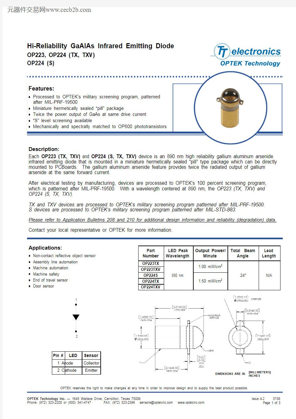
Each OP223 (TX, TXV) and OP224 (S, TX, TXV) device is an 890 nm high reliability gallium aluminum arsenide infrared emitting diode that is mounted in a miniature hermetically sealed “pill” type package which can be directly mounted to PCBoards. The gallium aluminum arsenide feature provides twice the radiated output of gallium arsenide at the same forward current.
After electrical testing by manufacturing, devices are processed to OPTEK’s 100 percent screening program, which is patterned after MIL-PRF-19500. With a wavelength centered at 890 nm, the OP223 (TX, TXV) and OP224 (S, TX, TXV).
TX and TXV devices are processed to OPTEK’s military screening program patterned after MIL-PRF-19500. S devices are processed to OPTEK’s military screening program patterned after MIL-STD-883.
Please refer to Application Bulletins 208 and 210 for additional design information and reliability (degradation) data.
Contact your local representative or OPTEK for more information.
Part Number
LED Peak Wavelength Output Power/Minute
Total Beam
Angle Lead Length
OP223TX 890 nm
1.00 mW/cm 2
24° N/A
OP223TXV 1.50 mW/cm 2
OP224S OP224TX OP224TXV
Applications:
? Non-contact reflective object sensor ? Assembly line automation ? Machine automation ? Machine safety
? End of travel sensor ? Door sensor
Pin # LED Sensor
1 Anode Collector
2 Cathode
Emitter
1
2
INCHES
[MILLIMETERS]
DIMENSIONS ARE IN:
OP223, OP224 (TX, TXV)
OP224 (S)
Absolute Maximum Ratings (T A = 25° C unless otherwise noted)
Storage Temperature Range -65o C to +150o C
Operating Temperature Range -55o C to +125o C
Lead Soldering Temperature [1/16 inch (1.6 mm) from case for 5 seconds with soldering iron](1) 260°
C Reverse Voltage 2.0 V
Continuous Forward Current 100 mA
Power Dissipation(2)100 mW
Notes:
1. No clean or low solids. RMA flux is recommended. Duration can be extended to 10 seconds maximum when flow soldering.
2. Derate linearly 1.00 mW/° C above 25° C.
Electrical Characteristics (T A = 25° C unless otherwise noted)
SYMBOL PARAMETER MIN
TYP
MAX
UNITS
TEST
CONDITIONS
Input Diode
E E (APT)Radiant Power Output
OP223
(TX,
TXV)
OP224 (S, TX, TXV)
1.00
1.50
-
-
-
-
mW I F = 50 mA
I F = 50 mA
V F Forward
Voltage 0.80 - 1.80 V I F = 50 mA I R Reverse
Current - - 100 μA V R= 2.0 V λP Wavelength at Peak Emission - 890 - nm I F = 50 mA
B Spectral Bandwidth between Half Power
Points
- 80 - nm I F = 50 mA
?λP /?T Spectral Shift with Temperature - 0.18 - nm/°C I F = Constant θHP Emission Angle at Half Power Points - 18 - Degree I F = 50 mA
OP223, OP224 (TX, TXV)
OP224 (S)
OP223 (TX, TXV), OP224 (S, TX, TXV)
0.9
1.01.11.21.31.41.51.6
1.71.8
T y p i c a l F o r w a r d V
o l t a g e (V )
Forward Voltage vs
Forward Current vs Temperature
0.0
0.5
1.0
1.5
2.0
2.5
3.0
3.5
10
20
30
40
50
60
70
80
90
100
Forward Current I F (mA)
N o r m a l i z e d O p t i c a l P o w e r
Optical Power vs I F vs
Temperature
1
2
3
4
5
6
0.2 ''0.4 ''0.6 ''0.8 '' 1.0 '' 1.2 '' 1.4 '' 1.6 '' 1.8 '' 2.0 ''
Distance (inches)N o r m a l i z e d O u t p u t P o w e r
-20
-15
-10
-5
5
10
15
20
Angular Displacement (Degrees)
R e l a t i v e R a d i a n t I n t e n s i t y
Forward Voltage vs Relative Radiant Intensity
vs Angular Displacement