LF系列B2B21单路直流电流变送器传感器
安全传感器模块 SRB 219IT 的用户说明书
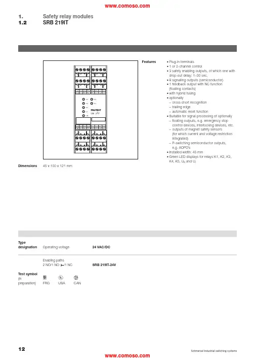
Safety relay modules SRB 219IT1.1.2Features•Plug-in terminals•1 or 2-channel control•3 safety enabling outputs, of which one with drop-out delay: 1–30 sec.•8 signalling outputs (semiconductor)•1 feedback output with NC function (floating contacts)•with hybrid fusing •optionally–cross-short recognition –trailing edge–automatic reset function•Suitable for signal processing of optionally –floating outputs, e.g. emergency stop control devices, interlocking devices, etc.–outputs of magnet safety sensors(for which current and voltage restriction integrated)–P-switching semiconductor outputs, e.g. AOPD ’s•Installed width: 45 mm•Green LED displays for relays K1, K2, K3,K4, K5, U B and U i45 x 100 x 121 mmDimensions HCDFRG USACANTest symbol (inpreparation)24 VAC/DCSRB 219IT-24VOperating voltage TypedesignationCircuit exampleH2•2-channel control (example without cross-short recognition), shown by way of example of a guard monitoring system with two contacts A and B, at least one of which is a contact with positive opening; with external reset button ®NB•S = feedback loop•The control circuit detects wire breaks and earth leakage in the monitoring circuit.•F1 = hybrid fusing•F2 = protection of signalling outputs •Power level: 2-channel control,suitable for contact amplification and contact multiplication throughcontactors or relays with positively driven contacts.Time delay•The time-delayed safety enabling output 37/38 can be set with a dropout delay of between 1 to 30seconds (see setting instructions).•The safety enabling output 37/38corresponds to STOP category 1to EN 60 204-1. The safety enabling outputs 13/14 and 23/24correspond to STOP category 0 to EN 60204-1.•The dropout delay can be set by means of potentiometer accessible on the front side of the housing.Premature switching off of the time delay•The dropout delay can be ended prematurely via the RT input.•The RT input facilitates the “switching off ” of time-delayed enabling output 37/38 before expiry of the set time.•The reset function is only effective during the dropout delay (afterswitching off the safety relay module).Internally a reset signal is generated by a “rising edge ” (activation of the 24 VDC signal at the RT input).RTS11Technical data1.3Operating voltage24 VDC –15%/+20%, residual ripple max. 10%24 VDC –15%/+20%, residual ripple max. 10%24 VAC, 48 VAC, 115 VAC, 230 VAC –15%/+10%24 VAC –15%/+10%Frequency range50/60 Hz (with AC operating voltage)Fuse of operating voltage internal electronic fuse F1, triggering current >0.5 A,reset after interruption of supply voltagePower consumption max. 3 VA, 3 W max. 5.2 VA, 4.4 WVoltage and current restrictionsof the control circuitsS11/S12, S21/S22, S31/S32max. 28 VDC/50 mAVoltage and currentof the control circuits X3/X5max. 28 VDC/100 mASwitching capacityof the enabling contacts230 VAC, 6 A ohmic (inductive with suitable suppressor circuit)Fuse of the enabling contacts 6 A slow-blowingSwitching capacityof the auxiliary outputs41/42, 53/54: 24 VDC, 2 A41/42: 24 VDC, 2 AFuse of the auxiliary contacts 2 A slow-blowingSwitching capacityof the signalling contacts Y1, Y2, Y3, Y4, Y5, Y6: 24 VDC, max. 10 mA Y1, Y2, Y3, Y4, Y5, Y6, Y7, Y8: 24 VDC, max. 10 mA Fuse of the signalling outputs internal electronic fuse F2, tripping current >100 mAExternal auxiliary voltages A1.1: 24 VDC –10%/+10%Utilisation categories13/14, 23/24, 33/34:13/14, 23/24:AC 15: 230 VAC, 6 A AC 15: 230 VAC, 6 A; DC 13: 24 VDC, 6 ADC 13: 24 VDC, 6 A37/38:AC 15: 230 VAC, 3 A; DC 13: 24 VDC, 2 A Pickup delay≤60 ms/≤200 ms (autostart/reset button)Dropout delay≤20 msVaristor circuitry*Shorter dropout delayContact material/contacts AgNi, AgSnO, self-cleaning, positively drivenContact resistance max. 100 mOhm in new stateAir clearance and creepage distance DIN VDE 0110-1 (04.97), 4 kV/2Cable connections Plug-in self-lifting screw terminalsmin. 0.2 mm2, max. 2.5 mm2, strand or multicore with wire end ferruleDimensions h/b/d 100 mm/45 mm/121 mmWeight340 g (400 g with transformer)360 gAmbient operating temperature–25°C ... 45°C (derating curve upon request)Mechanical life107switching cyclesTerminal markings DIN EN 50005/DIN 50013* upon request1.4Selection of applicationsStart configurationExternal reset button . . . . . . . . . . . . . . . . . . . . . . . . . . . . . . . . . . . . . . . . . . . . . . . . Page 16Automatic (time offset approx. 100 ms) . . . . . . . . . . . . . . . . . . . . . . . . . . . . . . . . . . . Page 16Start-up testing . . . . . . . . . . . . . . . . . . . . . . . . . . . . . . . . . . . . . . . . . . . . . . . . . . . . Page 16Sensor configurationEMERGENCY-STOP . . . . . . . . . . . . . . . . . . . . . . . . . . . . . . . . . . . . . . . . . . . . . . . . Page 17Guard . . . . . . . . . . . . . . . . . . . . . . . . . . . . . . . . . . . . . . . . . . . . . . . . . . . . . . . . . . Page 18P-switching semiconductor . . . . . . . . . . . . . . . . . . . . . . . . . . . . . . . . . . . . . . . . . . . Page 19Magnetic safety sensors . . . . . . . . . . . . . . . . . . . . . . . . . . . . . . . . . . . . . . . . . . . . .Page 19Actuator configuration/contact multiplication (KV)Single-channel . . . . . . . . . . . . . . . . . . . . . . . . . . . . . . . . . . . . . . . . . . . . . . . . . . . . Page 20Dual-channel . . . . . . . . . . . . . . . . . . . . . . . . . . . . . . . . . . . . . . . . . . . . . . . . . . . . . Page 20Diversitary . . . . . . . . . . . . . . . . . . . . . . . . . . . . . . . . . . . . . . . . . . . . . . . . . . . . . . .Page 20The following selection of applications is intended to provide users with assistance on which functionalities PROTECT SRBs offer.The circuit examples are suggestions which do not (cannot), however, release the user from his own responsibility to check the circuitry carefully in terms of its suitability for the individual case.Example: monitored start / without cross-short recognition / dual-channel controlMonitored startWithout cross-short recognitionDual-channel controlControl category:• Sensor configuration SK3• SRB module SK4• Actuator level SK4A CD ROM is provided with thiscatalogue as an additional service with the aid of which a completeconnection diagram can be compiled from the different individual functionali-ties.Since EN 954-1 does not require an overall control category for safety circuits, the control category (SK) is shown separately for upstream and downstream periphery as well as for the SRB module itself.Automatic start•Programming to automatic start by means of connecting terminals X3-X5.•The time offset between channels 1 and 2 is approx.100 ms.•Programming to endless time offset betweenchannels 1 and 2 by means of connecting terminals X3-X6.•If the operating mode “automatic start ” is used, an automatic restart after standstill in case of emergency to EN 60 204-1 Section 9.2.5.4.2 and 10.8.3 is to be prevented by higher ranking system.Start-up testing•Start-up testing, see page 6•Additional auxiliary contacts are to be provided as contacts serving the purposes of start-up testing.Time offset ∞Time offset 100 msS12Y3Y4S11S22S12S32S31Signalling outputsASingle-channel EMERGENCY STOP circuit to EN 418/EN 60947-5-5•Detects wire break and earth leakage in EMERGENCY STOP circuit.S12Y3Y4S11S22S21S32S31Signalling outputsABDual-channel EMERGENCY STOP circuit to EN 418/EN 60947-5-5•Detects wire break and earth leakage in the EMERGENCY STOP circuits.•Cross shorts in the EMERGENCY STOP circuits are not detected.S12Y3Y4S11S22S21S32S31ABSignalling outputsDual-channel EMERGENCY STOP circuit to EN 418/EN 60947-5-5•Detects wire breaks and earth leakage in the EMERGENCY STOP circuits.•Cross shorts in the EMERGENCY STOP circuits are detected.Safety relay modulesSelection of applications1.1.4Dual-channel guard monitoring to EN 1088•With positively opening position switches.•Detects wire break and earth leakage in the guard monitoring circuits.•Cross shorts between the guard monitoring circuits are detected.Dual-channel control with safety-orientated P-switching semiconductor components, e.g. AOPDs to EN 61496•Detects wire breaks and earth leakage in the control circuits.•Cross shorts between the monitoring circuits are not detected.Monitoring is performed at sensor level.•The terminals S11 and S21 are used here to feed the P-switching sensors.S12Y3Y4S11S22S12S32S31Signalling outputsASingle-channel control of magnet safety sensor switches to EN 60947-5-3•Detects wire breaks and earth leakage in the control circuits.ATTENTIONIt is only admissible to connect magnet safety sensor switches to the analysis circuitry if the requirements of standard EN 60947-5-3: 1999 are satisfied.The following minimum technical requirements must be satisfied:Switching capacity:min. 3 W Switching voltage:min. 30 VDC Switching current:min. 100 mAThe requirements are satisfied, for example, by the following Schmersal safety sensor:•BNS33-02z-2187S12Y3Y4S11S22S21S32S31ABS12Y3Y4S11S22S21S32S31ABSignalling outputsDual-channel control of magnet safety sensor switches to EN 60947-5-3•Detects wire breaks and earth leakage in the control circuits.ATTENTIONIt is only admissible to connect magnet safety sensor switches to the analysis circuitry if the requirements of standard EN 60947-5-3: 1999 are satisfied.The following minimum technical requirements must be satisfied:Switching capacity:min. 3 W Switching voltage:min. 30 VDC Switching current:min. 100 mAThe requirements are satisfied, for example, by the following Schmersal safety sensor:•BNS33-02z-2187without cross-short detection with cross-short detectionSelection of applications1.4Single-channel control•Suitable for contact amplification or contact multipli-cation by means of relay or contactor with positively driven contacts.*Feedback loopIf the feedback loop is not required it is to be replaced by a bridge.Dual-channel control•Suitable for contact amplification or contactmultiplication by means of relay or contactor with positively driven contacts.*Feedback loopIf the feedback loop is not required it is to be replaced by a bridge.Diversitary control (type SRB 219IT)•Suitable for contact amplification or contactmultiplication by means of relay or contactor with positively driven contacts.*Feedback loopIf the feedback loop is not required it is to be replaced by a bridge.Voltages A1+24 VDC/24 VAC A20 VDC/24 VAC A1.1Feed of the semiconductor outputs (24 VDC)InputsS11/S12Input channel 1S21/S22Input channel 2S31/S32Input for cross-short detection Outputs 13/14First safety enabling output (STOP 0)23/24Second safety enabling output (STOP 0)33/34Third safety enabling output (STOP 0) (in the case of type SRB 308IT)37/38Third safety enabling output (STOP 1), with dropout delay 1 ... 30 sec. (in the case of type SRB 219IT)41/42Auxiliary NC contact 53/54Auxiliary NO contactRT Premature termination of the dropout delayStart X1/X2Feedback loop X3Supply startX4Manual start (reset button)X5Automatic startX6Time offset to infinitySignalling outputs Y1Operating voltage Y2Internal voltage Y3Status channel 1Y4Status channel 2Y5Status feedback loop Y6Status start relay (K1)Y7Status stop 1 (K4, K5)Y8Auxiliary NO contact stop 0 (K2, K3)Terminal designation1.522Schmersal Industrial switching systemsSafety relay modules Diagnosis tables1.1.6Y4 – Channel 201111(S21-S22, S31-S32)Y5 – Feedback loop 11110(X1-X2)Y6 – Relay K100010Y7 – Relay K4, K500001Auxiliary NC contact 111 1 –> 0041-42Y8 – Auxiliary 00 –> 11NO contactY4 – Channel 201111(S21-S22, S31-S32)Y5 – Feedback loop 11110(X1-X2)Y6 – Relay K100010Auxiliary NC contact 111 1 –> 0041-42Auxiliary NO contact 00 –> 1153-54Type SRB 308IT Type SRB 219IT 。
互感器选型手册
1.1 概述............................................................................................................................................5 1.2 技术指标....................................................................................................................................5 1.3 选型说明....................................................................................................................................6 1.4 产品规格....................................................................................................................................7
1.4.9.1 AKH-L 零序电流互感器.....................................................................................47 1.4.9.2 AKH-3.3/P-φ型中压电动机保护专用电流互感器......................................49 1.4.9.3 JDG4-0.5 电压互感器.......................................................................................49 1.4.9.4 AMZK 系列电流互感器.......................................................................................50 1.5 安装方法...................................................................................................................................51 1.6 附录...........................................................................................................................................55 1.6.1 附录 1............................................................................................................................55 1.6.2 附录 2............................................................................................................................56 1.6.3 附录 3............................................................................................................................57 2. 霍尔传感器.......................................................................................................................................58 2.1 开环霍尔电流传感器..............................................................................................................58 2.2 闭环霍尔电流传感器..............................................................................................................62 2.3 直流漏电流传感器...................................................................................................................63 2.4 直流电压传感器......................................................................................................................65 3.BR 系列罗氏线圈变送器....................................................................................................................67 4.BA 系列交流电流传感器....................................................................................................................69 5.BM 系列模拟信号隔离器....................................................................................................................72 6.BD 系列电力变送器............................................................................................................................76 7. 典型案例...........................................................................................................................................82 8. 获得证书...........................................................................................................................................85
直流电流传感器
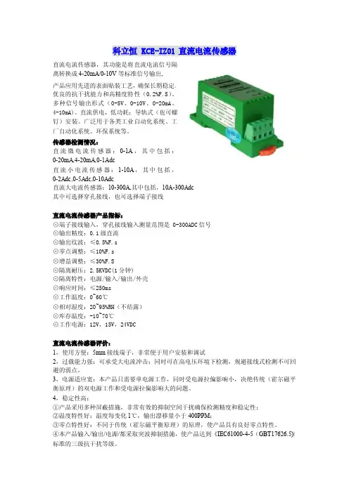
科立恒KCE-IZ01直流电流传感器直流电流传感器,其功能是将直流电流信号隔离转换成4-20mA/0-10V等标准信号输出,产品应用先进的表面贴装工艺,确保长期稳定。
优良的抗干扰能力和高精度特性(0.2%F.S)。
多种信号输出形式(0-5V、0-10V、0-20mA、4-10mA)。
直流供电,低功耗;导轨式(也可螺钉)安装。
广泛用于各类工业自动化系统、工厂自动化系统、环保系统等。
传感器检测情况:直流微电流传感器:0-1A,其中包括:0-20mA,4-20mA,0-1Adc直流小电流传感器:1-10A,其中包括,0-2Adc,0-5Adc,0-10Adc直流大电流传感器:10-300A,其中包括,10A-300Adc其中可选择穿孔接线,也可选择端子接线直流电流传感器产品指标:⊙端子接线输入,穿孔接线输入测量范围是0-300ADC信号⊙输出精度:0.1级直流⊙输出纹波:≤0.5%F.s⊙零点调整:≤10%F.s⊙增益调整:≤30%F.S⊙隔离耐压:2.5KVDC(1分钟)⊙隔离特性:电源/输入/输出/外壳⊙响应时间:≤250ms⊙工作温度:0~60℃⊙相对湿度:20~95%RH(不结露)⊙库存温度:-10~70℃⊙工作电源:12V,15V,24VDC直流电流传感器评价:1,使用方便:5mm接线端子,非常便于用户安装和调试2,过载能力强:可承受大电流冲击;同时可在高电压环境下检测,规避接线式检测不可回避的弱点。
3,电源适应宽:本产品只需要单电源工作,同时受电源拉偏影响小,决绝传统(霍尔磁平衡原理)的双电源工作和受电源拉偏影响大的问题。
4,稳定性高:①产品采用多种屏蔽措施,非常有效的抑制空间干扰确保检测精度和稳定性;②温度特性好;温度每变化1℃,输出漂移量小于400PPM;③零点特性好:不同于传统(霍尔磁平衡原理)的原理,使产品具有良好零点特性。
④本产品输入/输出/电源/都采取突波抑制措施,使产品达到《IEC61000-4-5(GBT17626.5)》标准的三级抗干扰等级。
横河FLXA21两线制电导率变送器快速启动手册
(C)Copyright 2000-2001/efont/The Electronic Font Open Laboratory.版权所有。 在满足下列条件的前提下,允许再发布经过或未经过修改的、源代码或二进制形式的本字体:
1. 源代码的再发布,必须保留上述版权声明,此许可条件细目及以下免责声明。 2. 二进制形式的再发布,必须在随同提供的文档和(或)其它材料中,复制上述版权声明,此许
All Rights Reserved Copyright © 2010, Yokogawa Electric Corporation
IM 12A01A02-12C-C 1st Edition : May 19, 2010-00
ii
u 安全注意事项
■ 本产品的保护、安全和改造相关注意事项
··为了安全使用本仪表以及由本仪表控制的系统,操作时请务必遵守说明书中的安全注意事 项。由于违反这些注意事项而产生的安全问题,横河电机不承担责任。
2.1 安装场所 ..........................................................................................................................4 2.2 电缆密封头的安装 ...........................................................................................................4 2.3 电源接线 ..........................................................................................................................6
丹东通博电器(集团) ZBLB 型 智能靶式流量变送器 说明书

ZBLB型智能靶式流量变送器 使 用 说 明 书辽 制 06000138号丹东通博电器(集团)有限公司1★ 概述为了满足现场总线控制的发展要求,实现与国际先进技术顺利接轨,我公司成功研制出一代新型流量仪表——ZBLB 型智能靶式流量变送器。
ZBLB 型智能靶式流量变送器是应用杠杆原理通过测应力的方法,经高精度的应变式双孔悬臂梁力传感器获取与流量变化一致的测量信号,此信号经A/D 转换器、微处理器、D/A 转换器等处理,输出4mA~20mA 开方电流模拟信号和叠加在此信号上的符合HART 协议的数字信号。
因此,具有对信号的线性处理精度高、抗干扰能力强、远程组态、监测、维护及校准等功能。
可与现场总线符合HART 协议设备联网使用,实现数字双向通讯与过程检测、控制的自动化。
并且可与模拟表兼容使用。
仪表具有现代流行壳体的设计,造型美观且各工作腔室隔离、安全可靠,精确的静压调整装置技术创新。
以上两项技术已获国家专利。
外观设计专利号为:99 3 21507.6。
静压调整实用新型专利号为:99 2 23728.9。
★ 主要性能及技术指标1. 性能● 液晶显示:现场显示有关变量信息; ● 两线制; ● 12V ~36V 供电;● 现场和远程组态功能:通过现场磁开关、远程手持器或PC 机加调试软件读写及组态各种过程参、变量,输出两线制4mA~20mA 开方电流及加载HART 协议通讯的各种参、变量值;● 自诊断信息功能:超出量程报警及各种故障诊断; ● 具有零点和满度校准功能; ● 具有防震、防电磁干扰强等特点; ● 防护等级:IP65;● 法兰标准:JB/T82.1-94(PN:2.5MPa);JB/T82.2-94(PN:4.0MPa、6.3MPa) ;(可按用户提供法兰标准制造)2. 技术指标● 负载电阻:见负载特性图;● 公称压力:2.5 MPa、4.0 MPa、 6.3MPa;● 精度等级:0.5%FS、1.0 %FS(挂重法)[未注明按1.0 %FS 供货];● 环境温度:-30℃~70℃;● 工作温度:T≤100℃(不带散热片),100℃<T≤400℃(带散热片); ● 阻尼时间选择:0秒~32秒;● 可指定报警上、下限,设置报警电流为3.8mA 或22mA ; ● 最大累积流量:99.99MT; ● 量 程 比:3:1;● 流量范围:1.5 m 3/h ~400m 3/h ; ● 电源引入口:M20×1.5(内螺纹)。
21 机电一体化设备组装与调试-1061

[0001-03272203-196ce082][单项选择题][中][基础知识][A]1.()的作用是使压缩空气干燥,过滤,使气体含有的杂质不会经过气体进入制动系统,从而保持制动系统的灵敏和有效。
A.干燥器B.压力表C.空气过滤器D.油雾器[0002-03272203-723a12af][单项选择题][中][基础知识][D]2.()是一种特殊的注油装置。
它以压缩空气为动力,将润滑油喷射成雾状并混合于压缩空气中,随压缩空气进入需要润滑的部位,达到润滑气动元件的目的。
A.干燥器B.压力表C.空气过滤器D.油雾器[0003-03272203-9576b98e][单项选择题][中][基础知识][A]3.压力表按其指示压力的基准不同,分为一般压力表、绝对压力表、差压表。
一般压力表以()为基准。
A.大气压力B.绝对压力零位C.两个被测压力之差D.水压[0004-03272203-286c70e1][单项选择题][中][基础知识][A]4.节流阀的主要作用是()。
A.控制液体流量B.控制电流C.两个被测压力之差D.水压[0005-03272103-45a97544][单项选择题][易][基础知识][B]5.机电一体化技术是以()技术为核心,强调各种技术的协同和集成的综合性技术。
A.自动化B.电子C.机械D.软件[0006-03272103-40cd1153][单项选择题][易][基础知识][C]6.机电一体化技术是以()部分为主体,强调各种技术的协同和集成的综合性技术。
A.自动化B.微电子C.机械D.软件[0007-03272303-a8991450][单项选择题][难][基础知识][B]7.在机电一体化产品的开发过程中,总体方案设计完成后应立即进行()。
A.样机设计(详细设计)B.此方案的评审、评价C.理论分析(数学模2)D.可行性与技术经济分析[0008-03272303-602d2841][单项选择题][难][基础知识][A]8.在机电一体化系统中,机械传动要满足伺服控制的基本要求足()。
HS812电流传感器手册
HS812电流传感器手册
YAV直流/交流电流传感器是一种检测装置,能感受到被测电流的信息,并能将检测感受到的信息,按一定规律变换成为符合一定标准需要的电信号或其他所需形式的信息输出,以满足信息的传输、处理、存储、显示、记录和控制等要求。
电流变送器是一种利用磁通门原理将被测直流电流转换成与该电流成比例输出的直流电流或电压信号的测量模块,原副边之间高度绝缘。
具有高精确度、高线性度、高集成度、体积小结构简单、长期工作稳定且适应各种工作环境的特点。
广泛地应用在新能源、石油、煤矿、化工、铁路、通信、楼宇自控等行业的电气设备的系统控制及检测—
直流微电流测量的电量隔离传感器,测量方式为穿孔结构,无插入损耗,过载能力强,抗电磁干扰能力强,电源适应范田宽,其输入和输出之间都不共地,输入信号为直流微电流,可以用于测量直流系统绝缘漏电流,该产品
可广泛用于直流电源系统各回路的绝缘骸测。
直流漏电流传感器是一种依据互感器电磁隔离、磁调制工作原理将被测直流微电流转换成直流电流、直流电压并隔离输出标准模拟信号或数字信号的装置。
产品符合国标GB/T13850—19xx送蒸可以直接将被测主回路交流电流或者直流电流转糗成按线性比例输出的DC4~20mA(通过250Q电阻转换DC1~5V或通过500Q电阻转
挽DC2—一10V)恒流环标准信号,连续输送到接收装置(PLC DCS DSP MCU无纸记录仪计算机或显示仪表)。
由于我们需要测量的电量一般都为高电压(57.7—380V)和大电流(1A—1000A),如果不对它们进行隔离和把幅度减小,将对人身安全和设备造成严重威胁,信号输入隔离一般采用电压互感器(PT)和电流互感器(CT)。
智能温度变送器一入一出24VDC供电
智能温度变送器(一入一出、24V DC供电)产品概述本智能温度变送器采用16位专用集成芯片设计,采集现场各种热电阻、热电偶等一次传感器的信号,经过放大、运算、隔离、抗干扰抑制等处理后,向控制系统或其它智能仪表输出直流电流或电压信号。
本智能配电器采用输入、输出、电源三端隔离技术,绝对电气隔离,断开过程环路中的直接电路(直流通路),使得检测和控制回路信号的稳定性和抗干扰能力大大增强,从而提高了整个系统的可靠性。
产品特点◆全智能、数字化、现场可编程◆ 16位高精度采集芯片设计◆测量分段线性化处理◆输入故障状态指示◆ 12.7mm超薄厚度,便于密集安装◆标准DIN35mm导轨安装技术参数◆传输精度:±0.2%F〃S (25℃±2℃)◆温度漂移:≤50ppm/℃(-20~+60℃)◆冷端补偿:±1℃(预热时间10分钟;热电偶有效)◆引线电阻:≤20Ω(热电阻有效)◆负载能力:电流≤500Ω;电压≥1MΩ◆响应时间:≤2 S◆介电强度:≥1500V AC(输入/输出/电源之间,漏电流1mA,测试时间1min)◆电磁兼容:符合IEC61000-4-4:1995中第三类工业现场对抗电磁干扰的要求◆供电电源: 20~30V DC◆功耗: 0.65W(24V供电,1路满载输出);◆工作温度: -20~+60℃输入信号○热电偶:K(0-1300℃); E(0-900℃); S(0-1600℃); B(300-1800℃);J(0-1200℃); R(0-1600℃); N(0-1300℃); T(0-400℃);Wre3-Wre25(0-2300℃); Wre5-Wre26(0-2300℃)○热电阻:Pt100(-199-600℃); Cu100(-50-150℃); Cu50(-50-150℃);BA1(-199-600℃); BA2(-199-600℃); Pt1000(-199-600℃);○其它输入、输出类型可特殊订制输出信号○ 4-20mA ○ 0-10mA ○ 0-20mA ○ 1-5V ○ 0-5V ○ 0-10V面板说明PWR :电源指示灯(绿色);工作时常亮。
中创智合科技有限公司产品手册 - ZH-KD07 直流 交流钳形漏电流传感器说明书
ZH-KD07直流/交流钳形漏电流传感器用户手册一.产品简介ZH-KD07直流/交流钳形漏电流传感器是专为在线测量600V 及以下直流、交流漏电流、电流而精心设计制造的,采用新CT 及数字集成技术,钳头细长设计,特别适合于排线密集的场所(电力计量系统、高铁系统、汽车电路检修等),钳形非接触测量,确保操作安全。
传感器体积小、精度高、性能稳定。
传感器可以连接相位检测分析仪、工业控制装置、数据记录仪、示波器、电力质量分析仪、高精度数字多用表等。
广泛适用于电力、通信、气象、铁路、汽车工业、油田、建筑、计量、科研教学单位、工矿企业等领域。
二.技术规格功能交直流漏电流、电流测试电源9V DC 6LR61碱性干电池,连续使用100小时,可以根据需要引出电源线,外接电源,便于长时间连续工作测试方式钳形CT,非接触测量钳口尺寸φ7mm(可钳导线外径)输入量程0mA~60.0A AC/DC 输出电压10mV/A;100mV/A(两档对应输出)输出范围1V peak max 分辨力1mA AC/DC 精度±3%FS(23℃±5℃,75%rh 以下)相位误差≤3°(AC 50Hz/60Hz;23℃±2℃)调零调节ZERO 键可以调零,消除地磁场及外电场的干扰输出接口φ3.5mm 音频插头/BNC 插头/4.0mm 双香蕉插头(按客户要求)输出线2芯屏蔽线,线长2m 尺寸高宽厚:168mm×65mm×34mm 频率响应AC:45Hz~400Hz DC:DC~10kHz 导线位置被检测导线处于钳口中心位置线路电压600V 及以下线路测试仪表质量170g(含电池)工作电流5mA 工作温湿度-10℃~50℃;80%rh 以下极限温度误差-10℃~0℃及40℃~50℃,误差最大增加2%FS 存放温湿度-10℃~60℃;70%rh 以下绝缘强度AC 3700V/rms(铁心与盒之间)适合安规IEC1010-1、IEC1010-2-032、污染等级2、CAT Ⅲ(600V)基本配置传感器1台、电池(6LR619V)1个、包装盒/用户手册1套三.原理及结构采用分割式铁芯和霍尔元件(hole element)组合,能同时检测交流和直流漏电流、电流,当被测电流I通过传感器时,霍尔元件感应输出一个霍尔电压V H,可以通过检测霍尔电压V H,来计算被测试电流I,霍尔电压V H比例于被测试电流I。
FZB-20系列智能变送仪表用户手册
FZB-21~26智能变送仪表通用手册1.1概述配电测控单元是采用通用的硬件方案,对直流操作电源系统的交流和直流配电回路的电压和电流等模拟量信号采用智能电量变送器检测;对配电回路各设备的状态和告警等开关量信号(无源开关触点)采用开关量采集模块采集。
最后,通过RS485接口把检测数据上传到电源监控装置统一处理。
下面分别介绍配电回路这些基础的测控单元的工作原理和技术指标。
1.1.1智能电量变送器a)工作原理:智能电量变送器采用输入、电源、通信三端隔离变换的技术拾取电源系统中各配电回路(整流器、蓄电池和直流母线)的电压和电流信号,实现对电源系统各配电回路运行参数的检测。
其中直流电压信号采用分压采样方式,直流电流信号采用75mV分流器取得,经放大、隔离和A/D变换,把模拟采样信号转换为数字信号供CPU读取,最后通过RS485串口将配电部分的运行参数上传到电源监控装置,进行显示、分析和判断,作为监控装置管理电源系统的重要依据。
模拟量测量采用零点和满度自校准技术,即使在环境温度变化或测量电路参数时变的条件下,仍能保证测量数据的准确性。
b)型号规格:FZB-20系列智能电量变送器的型号规格定义如下:FZB-□/□□工作电源电压标称测量范围输入信号类型智能电量变送器●输入信号类型用阿拉伯数字表示如下:21----直流电压;22----直流电流;23----三相交流电压;24----交流电压;25----交流电流;26----环境温度。
●标称测量范围用阿拉伯数字表示如下:直流电压变送器:1----0~300V(标称值220V);2----0~150V(标称值110V);3----0~75V(标称值48V);4----0~35V(标称值24V)。
直流电流变送器:1-----75mV~0~+75mV;2----0~75mV。
注:直流电流变送器的标称电流变比规格为:20A、30A、50A、75A、100A、150A、200A、300A、500A、750A、1000A、1500A、2000A。