MCR46, Nail - coin resistance, ver. 1
美孚力富SHC PM 460 安全数据表说明书
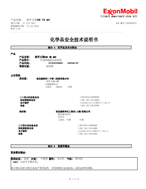
修订日期: 15 七月 2021 SDS 编号:7052602XCN最初编制日期: 13 Jan 2016 版本:2.03______________________________________________________________________________________________________________________化学品安全技术说明书产品产品名称: 美孚力富SHC PM 460 产品简介: 合成基础油及添加剂 产品代码: 2015A0204068, 643940-85 推荐用途: 润滑脂公司资料供应商:埃克森美孚( 中国 )投资有限公司美罗大厦17楼 天钥桥路30号上海市 200030 中国二十四小时应急电话 (+86************** 供应商联系电话 (+86*************电子邮件 *************************.cn 传真(+86*************供应商: 埃克森美孚化工商务(上海)有限公司紫星路1099号 闵行区上海市, 中国 中国二十四小时应急电话 供应商联系电话 电子邮件 传真(+86**************(+86**************************************.cn (+86*************紧急情况概述:物理状态: 固体 外观: 半流体 颜色: 灰白色 气味: 特有的 H402:对水生生物有害。
高压射向皮肤可能会造成严重的损伤 过度接触会造成眼部、皮肤或呼吸刺激。
修订日期: 15 七月 2021SDS 编号:7052602XCN 最初编制日期: 13 Jan 2016版本:2.03______________________________________________________________________________________________________________________该物料的危险性分类与化学品分类和危险性公示通则(GB 13690-2009)一致。
美国 AEMC 电流钳 MR461-561_EN

3. SPECIFICATIONS............................................................................. 9
3.1 Reference Conditions................................................................9 3.2 MR461 Specifications................................................................9 3.2.1 Electrical........................................................................9 3.2.2 Mechanical. .................................................................10 3.3 MR561 Specifications..............................................................10 3.3.1 Electrical......................................................................10 3.3.2 Mechanical. ................................................................. 11 3.4 Common Specifications (MR461 & MR561)............................ 11 3.4.1 Electrical...................................................................... 11 3.4.2 Mechanical. .................................................................12 3.4.3 Safety. .........................................................................13
Keithley仪器编程控制语句

Keysight Truevolt 34460数字万用表操作和维修指南-90918里都有本部分内容INITiate[:IMMediate]将触发系统状态由“空闲”更改为“等待触发”。
在接收到INITiate 命令后,指定的触发条件得到满足时,将开始进行测量。
此命令还从读数存储器中清除之前那组测量结果。
INITiate READ?将测量结果发送到仪器的输出缓冲区快(假定您在完成之后才发送FETCh?)。
INITiate 命令也是一个“重复的”命令。
这意味着在执行INITiate 后,您才能发送不影响测量结果的其他命令。
•在34460A 的读数存储器中最多可以存储1,000 个测量值,或在34461A 中最多可以存储10,000 个测量值。
如果读数存储器溢出,新的测量值将会覆盖存储的最旧的测量值;始终会保留最新的测量值。
不会产生任何错误,但在可疑数据寄存器的条件寄存器中设置Reading Mem Ovfl(读数存储器溢出)位(位14)(请参见状态系统简介)。
•要从读数存储器检索测量结果,请使用FETCh?。
使用DATA:REMove?或R?读取并擦除全部或部分得到的测量结果。
•可以使用ABORt命令返回到空闲状态。
FETCh?等待测量完成并将所有可用的测量结果复制到仪器的输出缓冲区。
读数保留在读数存储器中。
10,000 个测量值。
如果读数存储器溢出,新的测量值将会覆盖存储的最旧的测量值;始终会保留最新的测量值。
不会产生任何错误,但在可疑数据寄存器的条件寄存器中设置Reading Mem•INITiateMEASure:<function>?READ?*RSTSYSTem:PRESetREAD?开始一组新的测量,等待所有测量完成并传输所有可用的测量结果。
发送READ? 与发送INITiate类似,FETCh?紧随其后。
FETch?READ?数据。
•在34460A 的读数存储器中最多可以存储1,000 个测量值,或在34461A 中最多可以存储10,000 个测量值。
MCR100-6参数

汕头华汕电子器件有限公司SiliconControlledRectifiersHCR100 系列█ 主要用途单向可控硅, 用于继电器与灯控制、小型马达控制、较大晶闸管的门极 驱动、传感与检测电路等对应国外型号 MCR100 系列,P0102 系列█ 极限值(Ta=25℃)Tstg ——贮存温度 ………………………………………………… -40~150℃ Tj ——结温 …………………………………………………………-40~125℃ VDRM ——重复峰值断态电压 MCR100-6 ……………………………400V MCR100-8 ……………………………600V IT(RMS)——RMS 通态电流(均方值)…………………………… 0.8A IT(AV) ——平均通态电流(半正弦波,TC=74℃)…………………… 0.5A█ 外形图及引脚排列ITSM ——浪涌通态电流(1/2 周期,60HZ, 正弦波,不重复) …………… 10AVRGM —反向峰值门极电压 ………………………………………………5V IFGM ——正向峰值门极电流 ……………………………………………1.0A█ 电参数(Ta=25℃)参数符号 符 号 说 明 最小值 典型值 最大值 单 位 测 试 条 件IDRM重复峰值断态电流 10 200 uA V uA V 0.8 1.2VAK=VDRM 或 VRRM, Ta=25℃ Ta=125℃VTM IGT VGT峰值通态电压 门极触发电流 门极触发电压1.21.7 200ITM=1.0AVAK =7V, RL=100 ohm VAK =7V, RL=100 ohm Ta=25℃Ta=-40℃ V mAVAK =12V, RL=100 ohmVGD IH门极不触发电压 维持电流0.2Ta=125℃ 2Rth(j-c) Rth(j-a)5 1060.0 150 ℃/W ℃/WVAK =12V,初始电流=50mA Ta=25℃Ta=-40℃ 结到外壳 结到环境热阻 热阻汕头华汕电子器件有限公司SiliconControlledRectifiers对应国外型号 MCR100 系列,P0102 系列HCR100 系列█ 特性曲线图一、HCR100-8 电流降额 (参考 :管体温度) 图二、HCR100-8 电流降额 (参考 :环境温度)Tc 最大允许管体温度(℃)IT(AV) 平 均 通 态 电 流(A)Ta 最大允许环境温度(℃)IT(AV) 平 均 通 态 电 流(A)。
AU5800报警列表_翻译
3121 Sample Probe (FA) Error (Rotation) 3122 Sample Probe (FA) Error (Liquid Sensor) 3123 Sample Probe (FA) Error (Clot Sensor) 3124 Sample Dispenser (SA-S) Error 3125 Inner Wash Dispenser (SA-W) Error 3127 R1 Reagent Probe (FD01) Error (Up-Down) 3128 R1 Reagent Probe (FD01) Error (Rotation) 3129 R1 Reagent Probe (FD01) Error (LiquidSensor) ( 3130 R1 Reagent Dispenser (SA-R1) Error 3131 R1 Inner Wash Water Dispensing Disabled 3132 R2 Reagent Probe (FD11) Error (Up-Down) 3133 R2 Reagent Probe (FD11) Error (Rotation) ( 3134 R2 Reagent Probe (FD11) Error (LiquidSensor) 3135 R2 Reagent Dispenser (SA-R2) Error 3136 R2 Inner Wash Water Dispensing Disabled 3137 S/R1 Mixing Unit (FC01) Error (Up-Down) 3138 S/R1 Mixing Unit (FC01) Error (Rotation) 3139 S/R1 Mixing Unit (FC01) Error (Mixing) 3140 R2 Mixing Unit (FC11) Error (Up-Down) 3141 R2 Mixing Unit (FC11) Error (Rotation) 3142 R2 Mixing Unit (FC11) Error (Mixing) 3143 Cuvette Wash Unit (FB) Error 3144 Cuvette Wash Water Dispensing Disabled 3145 R1 Reagent Refrigirator (DA01) Error 3146 R2 Reagent Refrigirator (DA11) Error 3147 STAT Table (DC) Error (A)[A, B, C, D] 3148 Second Washing Well Pouring Error (A) 3149 Second Washing Well Draining Error 3150 Cooling Unit (DB) Error (A) 3151 Detergent Supply Pump (P5) Error 3180 ISE Sequence Error (A, B, C, D) 3181 ISE A/D Unit Error (A, B, C, D) 3182 ISE Buffer Dispenser (SA-ISE) Error 3183 ISE Mixture Rolling Pump (IB-S) Error 3184 ISE MID Rolling Pump (IB-M) Error 3185 ISE Mixing Unit (ISE-MIX) Error 3186 ISE Sample Pot Liquid Sensor Error 3187 ISE Sample Pot Overflow 3188 ISE Data Low 3189 ISE Analog Power Supply Error (A) 3200 Sample Short 3201 Sample Probe Clot Detect 3203 Sample Probe Short Aspiration 3204 Sample Probe Detergent Short (A) 3205 Sample Probe Detergent Empty (A) 3206 Sample Probe W2 Detergent Empty (A) 3208 Sample Prior Diluent Short (A)
gr-468 core标准

gr-468 core标准
gr-468 core标准是一种针对电信设备中使用的光电设备的通用可靠性保证要求。
该标准旨在确保电信设备中使用的光电设备的可靠性,包括设备的故障率、寿命、环境适应性、安全性等方面。
GR-468-CORE标准主要关注的是设备的可靠性,即设备在规定的时间内完成规定功能的能力。
它规定了设备的可靠性保证要求,包括设备的研发、生产、检验、使用等环节。
同时,该标准还规定了设备的可靠性测试和评估方法,以确保设备在实际使用中能够满足可靠性要求。
总之,GR-468-CORE标准是一种针对电信设备中使用的光电设备的通用可靠性保证要求,旨在确保设备的可靠性,提高设备的性能和质量。
HT46R48资料

General Description
The HT46R48 are 8-bit, high performance, RISC architecture microcontroller devices specifically designed for A/D applications that interface directly to analog signals, such as those from sensors.
Features
· Operating voltage: fSYS=4MHz: 2.2V~5.5V fSYS=8MHz: 3.3V~5.5V
· 19 bidirectional I/O lines (max.) · 1 interrupt input shared with an I/O line · 8-bit programmable timer/event counter with overflow
interrupt and 7-stage prescaler · On-chip crystal and RC oscillator · Watchdog Timer
· 2048´14 program memory · 64´8 data memory RAM · Supports PFD for sound generation · HALT function and wake-up feature reduce power
4 -C h a n n e l A /D C o n v e rte r
PBC
P o rt B
PB
PAC
P o rt A
PA
P B 0 /A N 0 ~ P B 3 /A N 3 P B 4~P B 7
特拉尼米克 TMC4671-EVAL 评估板说明书

Evaluation Board for DC,BLDC and StepperTMC4671-EVAL Evaluation BoardDocument Revision V1.1•2020-APR-02The TMC4671-EVAL is designed for evaluating all features of the TMC4671-LA.The evaluation board is part of TRINAMICs user-friendly plug-in system for chip evaluation.Just connect the TMC4671-EVAL with Landungsbruecke,the associated base board and a separate Power Stage(e.g.TMC-UPS-10A/70V)for easy configuration of PI controllers and feedback systems as well as driving a motor in standard modes like position,velocity or torque mode.Features•Servo Controller for DC,BLDC andstepper motors•Control of torque(FOC),velocity andposition by cascade control•Integrated Delta Sigma ADCs•5V Supply Voltage(onboard buck con-verter for VCCIO3.3V)•SPI and UART for communication withMicrocontroller•Realtime Monitoring Interface•ABN Encoder Interface,Digital HallInterface,Analog Hall Interface,Sine/-Cosine Encoder and Ref.-Switch In-putApplications•Laboratory Automation •Manufacturing •Semiconductor Handling •Robotics•Factory Automation•Test&Measurement•Life Science•Biotechnology•Liquid Handling Simplified Block Diagram©2021TRINAMIC Motion Control GmbH&Co.KG,Hamburg,GermanyTerms of delivery and rights to technical change reserved.Contents1Getting Started31.1First Start-Up (4)2Hardware Information5 3Evaluation Features in the TMCL-IDE6 4Revision History84.1Document Revision (8)1Getting StartedYou need•TMC4671-EVAL•Landungsbruecke or Startrampe with latest firmware (We recommend the Landungs-bruecke as it offers faster USB communica-tion.)•2x Eselsbruecke•TMC-UPS-2/24-EVAL or TMC-UPS-10A/70V-EVAL•BLDC or Stepper motor with supported feed-back system •USB interface •Power Supply•Latest TMCL-IDE V3.0and PC•Cables for interface,motors and powerPrecautions•Do not mix up connections or short-circuit pins.•Avoid bounding I/O wires with motor wires.•Do not exceed the maximum rated supply sup-ply voltage!•Do not connect or disconnect the motor while powered!•START WITH POWER SUPPLYOFF!Figure 1:Getting started1.1First Start-Up1.Make sure that the latest version of the TMCL-IDE is installed.The TMCL-IDE can be downloadedfrom /support/software/tmcl-ide/.2.Open the TMCL-IDE and connect the Landungsbruecke or Startrampe via USB to the computer.ForWindows8and higher is no driver needed,on Windows7machines the TMCL-IDE is installing the driver automatically.3.Verify that the Landungsbruecke or Startrampe is using the latestfirmware version.Thefirmwareversion is shown in the connected device tree.Figure2:Firmware Version4.The TMCL-IDE3.0needs room to show all important information and to provide a good overview.Therefore,arrange the main window related to your needs.We recommend using full screen.For evaluation boards it is essential to have access to the registers.Therefore open up the Register Browser(left side).For a better view click top right on the normal icon to get a maximized register browser window.5.The TMCL-IDE includes a dialogue for diagnostic tasks.Further,the dialogue provides an overviewof the connected motion controller and driver chips.Thus,a window pops up immediately after connecting the evaluation kit thefirst time.The window shows the actual status of the connections.The second tab of the dialogue offers the possibility to choose basic settings or to reset the module to factory1defaults.Figure3:Landungsbruecke Dialogue6.In the upper area of the Evaluation board youfind pin headers for connecting Digital Encoders,Dig-ital Hall Signals and Reference Switches.These input pins are5V tolerant and have extra protection and conditioning circuitry.Analog Hall Sensor Signals or Sine/Cosine Encoder can be processed as single ended analog signals at the respective pin headers in the lower area of the PCB.Power Supply and GND pins allow easy connection.Please check board schematics for proper connection of your feedback system.Figure4:Pin Headers on TMC4671-EVAL2Hardware InformationAll designfiles for our evaluation boards are available for free.We offer the original ECADfiles,Gerber data,the BOM,and PDF copies.Typically,the ECADfiles are in KiCAD format.Some(older)evaluation boards may only be available in Eagle,Altium,or PADS format.Please check schematics for Jumper settings and input/output connector description.Thefiles can be downloaded from the evaluation boards’website directly at https:/// support/eval-kits/.Note Iffiles are missing on the website or something is wrong please send us a note. 3Evaluation Features in the TMCL-IDEThis chapter gives some hints and tips on using the functionality of the TMCL-IDE,e.g.how to use the velocity mode or using the wizards.The register browser can be used to access every register of the TMC4671.Startfirst parametrization of the TMC4671-EVALwith the Wizard,providing guided dialogues to configure and calibrate your e configuration dialogues to setup PWM,Openloop generator,ADC calibra-tion,and feedback configuration.You can start the Wizard by clicking the marked icon(seefig.5).Figure5:Wizard Icon in TMCL-IDEThe TMCL-IDE also offers special dialogues for selectors,limits and PI controller configuration accessible from the left control pane.Figure6:Selectors and Limits dialogues in TMCL-IDEThe TMCL-IDE also provides ease-of-use dialogues for using drive modes(Torque Mode,Velocity Modeand Position Mode,seefig.7).Figure7:Control Mode Dialogues4Revision History4.1Document RevisionTable1:Document Revision。
- 1、下载文档前请自行甄别文档内容的完整性,平台不提供额外的编辑、内容补充、找答案等附加服务。
- 2、"仅部分预览"的文档,不可在线预览部分如存在完整性等问题,可反馈申请退款(可完整预览的文档不适用该条件!)。
- 3、如文档侵犯您的权益,请联系客服反馈,我们会尽快为您处理(人工客服工作时间:9:00-18:30)。
Nail/coin resistance – surface
MCR46
1. Mandatory Requirement
Verify the resistance to scratches from a nail or a ring on the finger, on the material or coating used for the outside surface of a product.
2. Compliance criteria
After the exposure with a nail or ring (coin) no visible scratches is accepted.
If the visible scratch can be erased by a finger it is accepted.
For more information read M-MCR46.
3. Scope
The requirement applies to products with the following characteristics: Product surfaces that the customer is expected to touch according to the expected user pattern.
4. Introduction
The intention of this demand is to verify that the surface can resist touching, being operated, cleaned etc. without getting scratched from a nail or a ring on the finger.
Abbreviations:
MCR = Mechanical Climatic Robustness
RS = Release for Sale
5. Purpose
Make sure that the daily use of the product by the customer will not damage the surface.
A nail should not leave a scratch on a high or low gloss surface.
The ring on a finger should not leave a colored scratch when touching the surface
6. Variable parameters
Not applicable.
7. Timing
The requirement must be verified before RS on samples that have to be processed according to the surface treatment process, which will be used for the running production.
8. Documentation
The test report shall contain all the information necessary to reproduce the test, and state the result of the test.
For more information see Annex 1.
9. Version history
Version Released:
Comments
Initials/Date
1.1 TMJ/27.10.2008 New template, nail and coin resistance.
Annex 1 – test report
The test report shall contain all the information necessary to reproduce the test.
In particular, the following shall be recorded:
−Date of verification.
−Company and person responsible for the verification.
−Identification of the device under test (DUT).
In this case sample material, surface treatment and supplier shall be specified.
−Identification of the test equipment, e.g. brand name, type number, serial number.
−If equipment is calibrated.
−Any effects on the DUT observed during or after the test.
−Test set up (e.g. photo).
−Measurement results, if any.
−The rationale for the pass/fail decision。