宏电RTU前置系统安装手册-windows v1.0_hs
布什安全设备D7050DH多路照电漏温传感器安装指南说明书
NoticesThese instructions cover the installation of theD7050DH Multiplex Photoelectric Duct Smoke Detector on a D7024 or a DS9400M 24 VDC Fire Alarm Control Panel (FACP) with a D7039 or DS9431 Multiplex Expansion Module installed. The D7024 and DS9400M requires ROM version 2.0 or greater. Install, test, and maintain the D7050DH according to these instructions, NFPA 72, local codes, and authority having jurisdiction (AHJ).Follow the procedures in these instructionsto avoid personal injury and damage to theequipment. Failure to follow theseinstructions can result in the D7050DH notoperating properly. Bosch is notresponsible for improperly installed, tested,or maintained devices.The D7050DH complies with Part 15 of the Federal Communications Commission (FCC) Rules and with the RSS-210 of Industry and Science Canada.D7050DH operation is subject to the following two conditions:1.It does not cause harmful interference.2.It must accept any interference it receives,including interference that might cause undesirable operation.1.0 DescriptionThe D7050DH (Figure 1) is Underwriters Laboratories, Inc. (UL) Listed and requires a D343 Duct Detector Housing. Use this detector with the D7024 or aDS9400M that includes a D7039 or DS9431 Multiplex Expansion Module.An LED indicator on the head flashes every 3 to 8 sec to ensure the D7050DH has power and the smoke sampling circuitry functions. This LED flashes at least once each second during an alarm confirming individual detector alarms. The D7050DH automatically resets after the alarm condition clears. 2.0 InstallationFor installation details, refer to the D7024 FACP Operation and Installation Guide (P/N: 31499), theD9400M Reference Guide (P/N: 44578), the D7039 Installation Guide (P/N: 38685), or the D S9431 Installation Instructions (P/N: 41381).Table 1: Maximum Wire Length Allowed foreach Multiplex BusWire Gauge Maximum 50 Ω for eachBus Loop18 AWG (1.02 mm) 3800 ft (1170 m)16 AWG (1.29 mm) 5950 ft (1810 m)14 AWG (1.63 mm) 5950 ft (1810 m)12 AWG (2.05 mm) 5950 ft (1810 m)Table 2: Maximum Number of DetectorsAllowed for each Multiplex BusWith Remote Test 40With Remote LED 50Without Annunciator 703.0 Wiring the D343You can wire the D343 in series as shown in Figure 2.4.0 Setting the AddressSet the D7050DH’s address using a flat-blade screwdriver to position the rotary switches(Figure 3) located on the back. Note that the switches click when turned.The valid address range is from 009 to 255. Refer to the D7024 Operation and Installation Guide (P/N: 31499) or the DS9400M Reference Guide (P/N: 44578) for additional address limitations.Figure 3 shows the A address range set at 095, allowing the D7039 to work with the D7024 FACP.5.0 Mounting1. Remove the tamper screw located in the recesson the top of the dust cover. 2. Remove the dust cover.3. Mount and wire the duct housing according to theD343 Installation Instructions (P/N: 48199). 4. Mount the D7050DH to the base by turning itclockwise until it clicks into place (Figure 4).6.0 ProgrammingFor multiplex programming, refer to the D7024 FACP Operation and Installation Guide (P/N: 31499)or theDS9400M Reference Guide (P/N: 44578).7.0 TestingTest detection devices immediately after installation. Test the D7050DH according to NFPA Chapter 7-1.6.2 (1999) or more often as required by local code.7.1 OperationalTesting2.If a D7050DH is in alarm, shut down the system.3.Remove the D7050DH and recheck for properwiring. If the problems persist, replace the affected D7050DH or exchange it with a known gooddetector. This determines if the problem is caused by the D7050DH.4.When the system is free of alarms, check eachD7050DH to ensure the red LED indicator on the head flashes. This confirms the detector isoperating properly.5.Test each D7050DH to ensure it causes a controlpanel alarm.6.Alarm the D7050DH by doing one of thefollowing:a.Place a magnet horizontally against the recessin the duct cover, centering it over the “T”marked on the head to activate an internalreed switch.b.Remove the duct cover and use a UL Listedaerosol smoke detector tester such as theHome Safeguard Industries’ 25S to simulatean alarm. Follow the instructions included inthe aerosol smoke detector tester.7.When a D7050DH alarms, the red LED indicatoron the head flashes at least once per second. Clear the alarm by initiating a system reset beforeproceeding to the next detector. 7.2 SensitivityTestingTest the D7050DH’s sensitivity to meet NFPA 72 requirements by conducting a Magnet Test (refer to Section 7.3 Magnet Test). You can also test sensitivity by measuring the calibration voltage pins with D1005 Test Cable, D344-RL, or D344-RT (refer to Section 7.4 Voltage Measurement Test). Calibration can be quickly determined by visually inspecting the D7050DH’s LED (refer to Section 7.2.2 Visual Check). These tests confirm whether or not the detector is within its factory marked calibration range.7.2.1 SensitivityTestThe control panel constantly monitors the D7050DH. If the detector exceeds the limits of the sensitivity thresholds, the control panel reports the detector in question and generates a fault condition.7.2.2 VisualCheckThe D7050DH includes the Chamber Check Automatic Trouble Indication that allows it to automatically show if its calibration is out of the factory-listed range. You can meet the NFPA guidelines for sensitivity testing by visually inspecting theD7050DH and checking the Alarm LED flash rate.If the calibration is out of range during power up or longer than 24 h, the Alarm LED double flashes. This LED single flashes when the detector is operating7.3 MagnetTestthe D343 cover for approximately 10 sec.2.Observe the LED. If the D7050DH is within thefactory marked calibration range, it goes into alarm and the Alarm LED flashes at least once persecond.a.If the D7050DH is too sensitive, the AlarmLED flashes six times rapidly (once every 0.5sec) and the detector goes into alarm.b.If the D7050DH is not sensitive enough, theAlarm LED flashes four times slowly (onceevery 2 sec) and the detector goes into alarm.3.If the D7050DH is not operating, it does not signalan alarm. Return the detector for repair.7.4 Voltage Measurement Test1.Plug a D1005 Test Cable (optional) into thecalibration voltage pin.2.Connect a digital voltmeter to the D1005.3.Connect the voltmeter’s negative terminal to theblack wire on the D1005 and connect the positiveterminal to the red wire. The white wire is notused.4.If a D344-RL or D344-RT is installed, use thevoltage monitor jacks as described below:a.The voltage measured by the voltmeter is halfthe sensitivity (in %/ft obscuration) of theD7050DH.b.Multiply the voltage by 2. The result must bewithin the factory-marked calibration rangeprinted on the label located on the bottom ofthe D7050DH.c.If the D7050DH is outside the factory-markedcalibration range, remove it and clean it. Orreplace it as described in Section 7.1OperationalTesting.d.After cleaning, recheck the calibration voltagemeasurement. If the D7050DH is still outsideof the factory-marked calibration range, returnit for recalibration to:National Repair Center130 Perinton ParkwayFairport, New York 144508.0 MaintenanceClean the detector and base at least once each year using a vacuum or clean dry compressed air. Pay particular attention to the screens. You might need to clean more often in dusty areas or areas of heavy insect concentration.1.Remove the D343’s cover.2.Remove the D7050DH from the base and cleanthe base with a clean cloth and common windowcleaner.3.Remove the D7050DH’s cover using a thin,flat-blade screwdriver to pry the chamber from the cover. Insert the screwdriver into the cover slotsand pry off the cover (Figure 5).4.Remove the cover of the detector chamber. Gentlypull the chamber cover up and away from the5.With the chamber cover removed, clean te insideof the cover with a vacuum or clean drycompressed air.Do not clean the D7050DH componentswith water or any liquid cleaner.6.Replace the chamber cover and ensure the hole forthe LED is properly aligned over the LED. Placethe cover parallel to the chamber and gently snapthe locking tabs into place.7.Replace the D7050DH’s cover, lining up the holesfor the LED.8.Return the D7050DH to its base and replace the9.0 SpecificationsTable 3: column width tableStandbyCurrentRefer to the D343 InstallationInstructions (P/N: 48199), the DS9400MReference Guide (P/N: 44578), and theDS6431 Installation Instructions(P/N: 41381)AlarmCurrentRefer to the D343 InstallationInstructions (P/N: 48199), the DS9400MReference Guide (P/N: 44578), and theDS6431 Installation Instructions(P/N: 41381)MinimumOperatingVoltage8 VDC peakPower-UpTime22 sec (maximum)InstallationTemperature+32°F to +100°F (0°C to +38°C)RelativeHumidity0% to 93% (non-condensing)RequiredAccessoriesD343 Duct Housing and Sample Tube Options D344-RT Remote TestD344-RL Remote LEDSMK-TM Test MagnetNotes。
RTU智能采集终端 数据采集设备 无线RTU数据采集器 RTU数据采集单元

远程终端设备RTU6200硬件手册 V1.00阿尔泰科技发展有限公司版权声明本产品是由阿尔泰科技发展有限公司(art control)开发,受知识产权保护。
任何人未¾\u25480X权不得加以仿冒、盗用、非法拷贝。
此份文件内所述得内容,除了商标、产品和软件名称外,其余皆不得以任何形式复制、转换、重述后储存在任何形式的系统中。
除非¾\u36807X阿尔泰科技发展有限公司的书面同意,否则不得以任何形式或文字转译本手册中所述涉及知识产权的内容。
出现在本手册中的产品、公司名称,或属已注册商标或版权声明,其权利由其后所代表的公司所有,除了用作说明和解释用途外,这些有版权或已注册商标、产品和公司名称不得仿冒。
法律责任这本手册仅作参考之用,不作任何形式的保证。
此文件主要目的在于提供使用者使用安装本产品的相关咨讯,作为参考文件之用。
使用者若沿用本手册内容作其他方面的使用参考而导致任何权益、产品等损害的话,本公司不负任何责任,同时为产品更新之需要,本公司将保留修改本手册的权利,不再另行通知,未按本手册使用后果自负。
第一章 RTU6200概述RTU6200系列远程终端设备是阿尔泰科技发展有限公司集多年的开发、工程经验设计的新型RTU产品,它可实现对工业现场信号的采集和对现场设备的控制。
RTU6200 系列远程终端设备的硬件基于功能强大的32位ARM7 核心的LPC2292处理器,拥有256K flash、512K SRAM。
开关量输入/输出、模拟量输入,RS232/RS485,并带有兼容CAN2.0的总线接口、精确的温湿度传感器和RTC时钟,可为现场应用提供功能强大的硬件平台。
各种总线与外部均采用光藕隔离。
5.7"的带有触摸功能的单色液晶显示屏使与其可以构建完整的用户界面。
更方便开发。
其具有多种配置和多种功能的选择,我们可根据用户的实际需求进行量身定制、系统集成、开发和应用。
RTU6200 是基于白色蓝底显示的图形LCD(320*240 像素)。
泓格模拟量输入卡ISO813快速上手手册
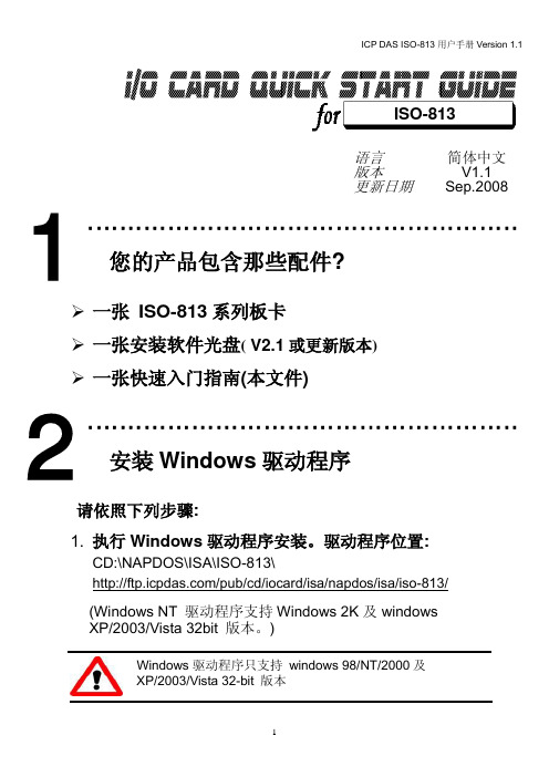
1
2
3
4
5
6
SW1 : 基准地址
Base Adders 200-20F 210-21F 220-22F() 230-23F : 300-30F : 3F0-3FF
A9 1 OFF OFF OFF OFF : OFF : OFF A8 2 ON ON ON ON : OFF : OFF A7 3 ON ON ON ON : ON : OFF A6 4 ON ON ON ON : ON : OFF A5 5 ON ON OFF OFF : ON : OFF A4 6 ON OFF ON OFF : ON :
免责声明
凡使用本系列产品除产品质量所造成的损害,泓格科技股份有限公司不承担任何法律责任。泓格科 技股份有限公司有义务提供本系列产品可靠而详尽资料,但保留修订权利,且不承担使用者非法利用资 料对第三方所造成侵害构成的法律责任。
安全导则
在系统最终调试之前,您应该对控制设备进行完整的控制功能测试和必要的安全性能测试。 您在安装、调试、试运行控制设备的过程中,应保证系统涉及或可能涉及设备的安全运行。 由于不可预见的设备错误或操作错误随时可能发生,您在操作中应提高警觉,避免造成此类危及人 身安全或设备损害的事件。
泓格科技(ICP DAS)主网页
专业技术支持 代理商及订购信息 增强设备功能的相关信息 常见问题 应用案例
联络方式 Service@ Copyright ©2008 by ICP DAS Co., Ltd. All right are reserved
1. 检查 Switch1 (此设定值 须与 I/O 地址设定相符)及 Jumper1 and Jumper2 (此
弘讯电脑说明书

弘讯电脑说明书目录一、6000使用规范 .................................................................................错误!未定义书签。
二、操作面板之安装: ............................................................................ 错误!未定义书签。
三、操作面板.......................................................................................... 错误!未定义书签。
四、电源器之安装: ........................................................................................ 错误!未定义书签。
五、RACK的组合............................................................................................. 错误!未定义书签。
5-1、CPU的连接.................................................................................................................. 错误!未定义书签。
5-2、IO板的连接 ................................................................................................................. 错误!未定义书签。
5-2-1、输入介面板的连接.................................................................................................. 错误!未定义书签。
系统安装手册(Windows版)-v1.0
iES600Pro/DMS1000E主站系统系统安装手册(Windows版)积成电子股份有限公司电网自动化事业部修订历史记录目录1.概述 (1)1.1.设备命名和IP地址规划 (1)1.2.磁盘分区 (1)1.3.操作系统的安装与配置 (2)2.Oracle安装 (5)2.1.安装版本说明 (5)2.2.Windows 64位操作系统下的Oracle安装 (5)2.3.Oracle服务端安装 (5)2.4.创建监听 (9)2.5.创建数据库实例 (14)2.6.Oracle客户端安装 (23)2.7.配置服务名 (29)2.8.设置Oracle环境变量 (33)3.VS2005安装 (33)3.1.关于32位与64位 (33)3.2.安装Visual Studio 2005 (34)3.3.补丁安装 (40)3.3.1.安装Visual Studio 2005 SP1补丁 (40)3.3.2.安装Vista、Win7和Server 2008补丁 (41)3.4.设置Visual Studio 2005环境变量 (42)4.使用脚本设置环境变量 (42)5.QT安装 (43)5.1.安装QT3.3.8 (43)5.2.安装QT3.3.8的补丁 (48)5.3.拷贝安装QT (48)6.应用程序的部署 (48)6.1.建立目录 (48)6.2.编译程序 (48)6.3.修改初始化文件 (48)6.4.程序分发 (49)6.5.注册服务 (49)6.6.运行检查 (49)1.概述1.1.设备命名和IP地址规划根据配置清单,总成人员首先要明确设备的用途,根据设备用途为机器命名。
设备名称遵循以下原则:1)体现机器用途;2)机器名尽量不带“-”或“_”,如“ADM-01-A”或“ADM_01_A”,某些系统或应用程序(如Oracle)不支持这个字符,而且名称显得冗长。
3)维护工作站、调度员工作站、监控工作站等命名要区分开。
RTU控制系统的安装调试方法

RTU控制系统的安装调试方法1. 简介RTU(Remote Terminal Unit)控制系统是一种用于监控和控制远程设备的技术。
本文档旨在介绍RTU控制系统的安装和调试方法,帮助用户顺利部署该系统。
2. 硬件安装在开始安装之前,确保已经获得了RTU控制系统的硬件设备,并具备以下条件:- 适当的安装空间和支架,以确保设备稳固安全地安装。
- 与设备连接的电源和通信线路,确保供电和数据传输的正常进行。
- 依照设备的安装指南,正确布线和连接各个外围设备(如传感器、执行器等)。
3. 软件安装RTU控制系统通常由软件和硬件组成。
在进行软件安装之前,请根据系统要求准备好以下内容:- 操作系统:确保正确的操作系统已经安装在RTU设备上,以支持控制系统软件的运行。
- 驱动程序:根据设备要求,安装所需的驱动程序,以确保设备与操作系统正常通信。
- 程序安装:将RTU控制系统的软件程序安装到设备中。
- 参数配置:根据系统要求,对软件进行必要的参数配置,以满足特定的控制需求。
4. 调试步骤安装完成后,进行以下步骤对RTU控制系统进行调试:1. 确认硬件连接:检查每个硬件设备的连接情况,包括传感器、执行器、通信线路等。
2. 供电检查:验证设备的供电情况是否正常,检查电源接口、开关状态及电源指示灯。
3. 程序运行:启动RTU控制系统的软件程序,确保程序能够正常运行。
4. 通信测试:通过系统界面进行通信测试,检查各个设备之间的通信是否正常。
5. 测量校准:如果涉及传感器测量,应进行校准操作,确保数据准确可靠。
6. 控制测试:通过控制界面进行控制测试,验证系统对设备的控制是否准确。
5. 故障排除在调试过程中,可能会遇到一些问题和故障。
以下是一些常见的故障排除方法:- 检查电源:确认电源供应是否正常,检查电源线路和电源开关。
- 检查通信线路:检查通信线路是否损坏、连接不良或过长。
- 驱动程序更新:如果设备之间通信失败,可以尝试更新驱动程序以解决兼容性问题。
FENISH RTU F-0601 产品手册(上位机)
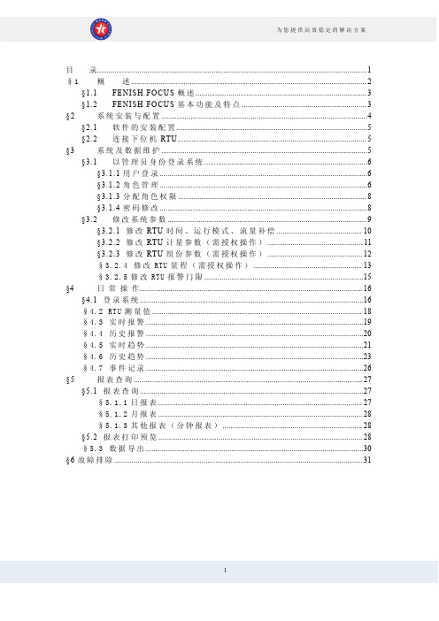
目录 (1)§1概述 (2)§1.1FENISH FOCUS概述 (3)§1.2FENISH FOCUS基本功能及特点 (3)§2系统安装与配置 (4)§2.1软件的安装配置 (5)§2.2连接下位机RTU (5)§3系统及数据维护 (5)§3.1以管理员身份登录系统 (6)§3.1.1用户登录 (6)§3.1.2角色管理 (6)§3.1.3分配角色权限 (8)§3.1.4密码修改 (8)§3.2修改系统参数 (9)§3.2.1修改RTU时间、运行模式、流量补偿 (10)§3.2.2修改RTU计量参数(需授权操作) (11)§3.2.3修改RTU组份参数(需授权操作) (12)§3.2.4修改RTU量程(需授权操作) (13)§3.2.5修改RTU报警门限 (15)§4日常操作 (16)§4.1登录系统 (16)§4.2RTU测量值 (18)§4.3实时报警 (19)§4.4历史报警 (20)§4.5实时趋势 (21)§4.6历史趋势 (23)§4.7事件记录 (26)§5报表查询 (27)§5.1报表查询 (27)§5.1.1日报表 (27)§5.1.2月报表 (28)§5.1.3其他报表(分钟报表) (28)§5.2报表打印预览 (28)§5.3数据导出 (30)§6故障排除 (31)§1概述§1.1FENISH FOCUS概述FENISH FOCUS站控系统软件可运行于Win98/Win2000/WinXP等多种操作系统,提供友好的人机界面,分为组态、运行两部分。
OPEN-3000系统使用手册-前置

OPEN-3000能量管理系统系统使用手册之前置国电南瑞科技股份有限公司二零零七年八月前言本手册是OPEN-3000系统前置工具使用说明,结合工程化工作将各类编辑工具的使用操作进行了较为详细的说明。
该手册主要适用于初次使用OPEN-3000前置系统的人员以及系统工程化人员,同时也可以作为前置工具使用的速查手册,希望对使用OPEN-3000系统者有所帮助。
鉴于系统相应软件功能在不断更新,所以本手册也会随之做定期相应更新和完善。
目录第一章 FES子系统概述 (1)1.1结构与运行方式 (1)1.2控制策略 (3)1.2.1 人工控制 (3)1.2.2 通道分配原则 (3)1.2.3 负荷均分原则 (4)1.2.4 通道、厂站投退判断 (4)1.2.5 值班、备用原则 (4)1.3配置方案 (5)1.3.1 前置服务器配置 (5)1.3.2 终端服务器配置 (5)1.4主要模块进程 (5)1.5主要进程分布 (7)1.6厂站通道定义 (10)第二章 FES子系统硬件配置 (11)2.1机柜布置 (11)2.2数据采集终端服务器 (12)2.2.1初步选择试验型号 (12)2.2.2 输出端子 (12)2.3通道箱及通道板 (13)2.3.1通道箱 (13)2.3.2 通道板 (13)2.4端子排 (14)第三章 FES子系统规约设置 (16)3.1CDT规约 (16)3.2IEC101/IEC104规约 (17)3.3 µ4F规约 (18)3.4DL476-92规约 (19)第四章 FES子系统图形操作 (23)4.1通用操作 (23)4.2图元操作 (26)4.3WEB侧图形操作 (31)第五章 FES子系统操作界面 (32)5.1通道原码显示界面(FES_CDISP) (32)5.2通道报文显示界面(FES_RDISP) (33)5.3实时数据显示界面(FES_REAL) (34)5.4事件显示界面(FES_EVENT) (35)5.5网络交换报文显示界面(FES_NETDISP) (36)5.6TASE2远方读取变量界面(FES_READ_VAR) (37)5.7运行监视界面(FES_TABLE) (40)5.8统计查询界面(FES_QUERY) (44)5.9模拟器界面(FES_SIM) (48)第六章 FES远程维护工具 (50)6.1人工控制、切换工具 (50)6.2人工模拟遥信变位 (50)6.3人工模拟变化遥测 (51)6.4人工模拟SOE (52)6.5实时数据查询 (53)6.6通道报文监视 (55)6.7通道原码监视 (56)6.8网络报文监视 (56)6.9共享内存监视 (57)第七章 HMD1智能MODEM使用说明 (59)7.1概述 (59)7.2功能 (59)7.3参数 (59)7.4指示灯定义 (60)第八章 HMD2智能数字隔离板使用说明 (68)8.1概述 (68)8.2功能 (68)8.3参数 (68)8.4指示灯定义 (69)8.5运行状态设置 (69)第九章 前置数据库表说明 (74)9.1设备类 (74)9.1.1 通讯厂站表 (74)9.2.2通道表 (74)9.1.3前置配置表 (75)9.1.4前置网络设备表 (76)9.2定义表类 (76)9.2.1前置遥测定义表 (76)9.2.2前置遥信定义表 (77)9.2.3前置遥脉定义表 (77)9.2.4前置遥信转发表 (78)9.2.5前置遥测转发表 (78)9.3规约类 (78)9.3.1 CDT规约表 (78)9.3.2 IEC101规约表 (79)9.3.3 IEC104规约表 (79)9.4其他类 (79)9.4.1 DL476分组定义表 (79)9.4.2 DL476分组转发表 (79)9.4.3 规约映射表 (80)第一章 FES子系统概述前置子系统(Front End System)作为OPEN-3000系统中实时数据输入、输出的中心,主要承担了调度中心与各所属厂站之间、与各个上下级调度中心之间、与其它系统之间以及与调度中心内的后台系统之间的实时数据通信处理任务,也是这些不同系统之间实时信息沟通的桥梁。
- 1、下载文档前请自行甄别文档内容的完整性,平台不提供额外的编辑、内容补充、找答案等附加服务。
- 2、"仅部分预览"的文档,不可在线预览部分如存在完整性等问题,可反馈申请退款(可完整预览的文档不适用该条件!)。
- 3、如文档侵犯您的权益,请联系客服反馈,我们会尽快为您处理(人工客服工作时间:9:00-18:30)。
文档版本 01 (2013-9-10)
iii
RTU 前置系统 使用说明书
插图目录
插图目录
图 2-1 RTU 前置系统安装流程图 .................................................................................................................... 2-2 图 2-2 Java 安装页面......................................................................................................................................... 2-2 图 2-3 安装验证页面........................................................................................................................................ 2-3 图 2-4 验证 Java 安装成功............................................................................................................................... 2-3 图 2-5 选择自定义安装“Custom”.................................................................................................................. 2-4 图 2-6 修改安装路径界面................................................................................................................................ 2-4 图 2-7 “Wizard Completed”界面 ..................................................................................................................... 2-5 图 2-8 选择服务类型........................................................................................................................................ 2-6 图 2-9 连接数.................................................................................................................................................... 2-6 图 2-10 数据库端口配置 .................................................................................................................................. 2-7 图 2-11 字符集设置.......................................................................................................................................... 2-7 图 2-12 数据库服务名称选择 .......................................................................................................................... 2-8 图 2-13 数据库密码设置 .................................................................................................................................. 2-8 图 2-14 数据库安装和配置成功 ...................................................................................................................... 2-9 图 2-15 RTU 安装向导页面 ............................................................................................................................ 2-10 图 2-16 选择安装位置.................................................................................................................................... 2-10 图 2-17 设置开始菜单中的快捷方式名称 .....................................................................................................2-11 图 2-18 现场项目名称设置 .............................................................................................................................2-11 图 2-19 端口配置............................................................................................................................................ 2-12 图 2-20 数据库连接信息 ................................................................................................................................ 2-12 图 2-21 安装界面............................................................................................................................................ 2-13 图 2-22 安装完毕............................................................................................................................................ 2-13 图 2-23 监控服务运行状态页面 .................................................................................................................... 2-14 图 2-24 RTU 前置登陆页面 ............................................................................................................................ 2-14 图 3-1 提示数据库未启动.................................................................................................. 错误!未定义书签。 图 3-2 Web 服务端口被占用............................................................................................................................. 3-2 图 3-3 端口配置................................................................................................................................................ 3-2 图 3-4 初始化数据库错误................................................................................................................................ 3-3