CAI022
深低温星上定标黑体源研究

深低温星上定标黑体源研究董惠文1,练敏隆1,马思宇1,李洋1,裴景洋1,于志1,凤晓华2(1.北京空间机电研究所,北京 100094; 2.中国科学院宁波材料技术与工程研究所,浙江宁波 315201)摘要:为匹配红外空间载荷低温光学镜头的光学性能,降低背景噪声,实现载荷高精度星上定标,研制了一种基于制冷机主动制冷的深低温星上定标黑体源装置(低温100 K工作),该星载黑体源装置由面黑体辐射体、低温制冷机主动制冷系统、冷量传输热管及精密测控温系统组成,通过载荷级真空辐射定标实验校验,最终实现红外遥感器对星上定标黑体源宽光谱(2 ~ 16 μm)、高发射率(0.987)、深低温(100 K)的高精度定标源需求。
该深低温星上定标黑体源可用于对极远极冷极弱目标探测的红外载荷星上辐射定标,其高精度、低功耗、通用性的工程化设计方法,为后续相关研究及推广提供技术支撑。
关键词:深低温;星上定标黑体;真空辐射定标中图分类号:TB94 文献标志码:A 文章编号:1674-5795(2023)06-0067-09Development of deep cryogenic onboard calibration blackbody sourceDONG Huiwen1, LIAN Minlong1, MA Siyu1, LI Yang1, PEI Jingyang1, YYU Zhi1, FENG Xiaohua2(1.Beijing Institute of Space Mechanical and Electrical Engineering, Beijing 100094, China;2.Ningbo Institute of Materials Technology & Engineering, Chinese Academy of Sciences, Ningbo 315201, China)Abstract: In order to match the optical performance of low⁃temperature optical lenses of infrared space payloads, re⁃duce background noise, and achieve high⁃precision on⁃board calibration of payloads, a deep⁃low temperature on⁃board calibration blackbody source device based on active refrigeration (operating at a low temperature of 100 K) was proposed. The spaceborne blackbody source device is composed of a face⁃blackbody radiator, an active refrigeration system of a low temperature chiller, a heat pipe of cooling capacity transmission, and a precise temperature measurement and control sys⁃tem. It was verified through vacuum radiation calibration experiment that the requirements of infrared remote sensors for the on⁃board calibration blackbody source: wide spectrum (2 ~ 16 μm), high emissivity (0.987) and deep low temperature (100 K) were achieved. The blackbody source for calibration on a cryogenic satellite can be used for on⁃board radiation calibration of infrared payloads for the detection of extremely distant, extremely cold and weak targets. The high precision, low power consumption and universal engineering design method of the calibration source provides technical support for subsequent related research and promotion.Key words: deep cryogenic temperature; onboard calibration blackbody source; vacuum radiation calibration0 引言红外光学遥感载荷可应用于实现资源普查、环境监测、海洋观测、气象分析、深空探测、空间引力波探测、天文观测等领域。
一种V型阵列的二维波达方向估计的新方法

一种V型阵列的二维波达方向估计的新方法
令瀚;叶中付
【期刊名称】《计算机仿真》
【年(卷),期】2008(025)006
【摘要】波达方向估计是阵列信号处理的一个重要研究方向,在雷达、通信、声纳、地震勘测等领域都有着广泛的应用前景.它已成为阵列无源探测和智能天线中的关
键技术.针对二维信号,本文研究一种基于V型阵二维波达方向估计的新算法.该算法根据阵列结构的特点形成多个需要的相关矩阵,构造一个特殊大矩阵并经特征分解
获得信号子空间的估计,最后利用2D-ESPRIT方法实现二维角度估计,可以解决β
角兼并信号的波达方向估计问题,无需谱峰搜索且信号参数自动配对.最后用计算机
仿真验证了该算法的有效性.
【总页数】5页(P113-116,123)
【作者】令瀚;叶中付
【作者单位】中国科技大学电子工程与信息科学系,安徽,合肥,230027;甘肃省定西
市气象局,甘肃,定西,743000;中国科技大学电子工程与信息科学系,安徽,合
肥,230027
【正文语种】中文
【中图分类】TP393
【相关文献】
1.一种基于双平行线阵相干源二维波达方向估计的新方法 [J], 曾操;廖桂生;王洪洋
2.一种用于未知噪声背景中相干源二维波达方向估计的新方法 [J], 李平安;孙进才
3.一种基于三维阵列结构二维波达方向估计的新方法 [J], 丁君;徐腾
4.一种用于矩形阵列的二维波达方向估计方法 [J], 王剑书;樊养余;杜瑞;吕国云
5.一种基于平行互质阵列时空扩展的二维波达方向估计 [J], 赵慧; 赵晶; 曾伟
因版权原因,仅展示原文概要,查看原文内容请购买。
SnBi36Ag0.5Sbx_焊料合金组织与性能
第14卷第4期2023年8月有色金属科学与工程Nonferrous Metals Science and EngineeringVol.14,No.4Aug. 2023SnBi36Ag0.5Sb x 焊料合金组织与性能朱文嘉, 赵中梅, 龙登成, 张欣, 秦俊虎*, 卢红波(云南锡业新材料有限公司, 昆明 650501)摘要:向SnBi36Ag0.5合金中加入不同含量的Sb 元素,按设计的质量比将Sn 、Bi 、Ag 、Sb 纯金属在450 ℃熔化,保温6 h 、320 ℃浇铸,制备成SnBi36Ag0.5Sb x (x =0.3、0.7、1.0、1.5、2.0)焊料合金。
并对合金的显微组织、相成分、熔点、润湿性、力学性能进行表征,研究Sb 含量对合金性能的影响。
结果表明该合金由网状Bi 相、基体Sn 相、颗粒状和短杆状的富Bi 相、Ag 3Sn 构成。
在一定范围内,Sb 元素绝大部分固溶于Sn 基体相中,难以析出SnSb 化合物。
Sb 的添加使合金的液相线温度和熔程明显提高。
随着Sb 含量增高,润湿时间越长,润湿力越低,润湿性能下降。
当Sb 含量为2%时,抗拉强度最高值为97.09 MPa 。
添加少量的Sb 对Sn-Bi 系中Bi 合金焊料性能产生明显影响。
关键词:SnBi36Ag0.5Sb x 焊料合金;显微组织;润湿性;力学性能中图分类号:TG425 文献标志码:AStudy on microstructure and properties of SnBi36Ag0.5Sb x solder alloyZHU Wenjia, ZHAO Zhongmei, LONG Dengcheng, ZHANG Xin, QIN Junhu *, LU Hongbo(Yunnan Tin New Material Co., Ltd. , Kunming 650501, China )Abstract: SnBi36Ag0.5Sb x (x =0.3, 0.7, 1.0, 1.5 and 2.0) solder alloy was prepared by melting pure Sn, Bi, Ag, Sb at 450 ℃ for 6 h and then casting at 320 ℃ according to the mass ratio . The microstructure, phase composition, melting point, wettability, and mechanical properties of the alloy were characterized to study the effect of Sb content on the properties of the alloy. The results showed that the alloy was composed of reticulated Bi phase, matrix phase of Sn, granular and short rod-shaped Bi-rich phase, and Ag 3Sn compound. In a certain range, most Sb elements solutionized in the matrix phase of Sn rather than as the SnSb compound liberation. The liquidus temperature and melting range of the alloy were increased by the addition of Sb. With increasing Sb content, the wettability decreased due to the worse wetting time and the wetting force. When the Sb content was 2%, the maximum tensile strength was 97.09 MPa. The addition of a small amount of Sb can significantly affect the properties of the Bi alloy solder in the Sn-Bi system.Keywords: SnBi36Ag0.5Sb x solder alloy ; microstructure ; wettability ; mechanical propertiesSn-Bi 系焊料是低温无铅焊料的重要组成部分,与Sn-In 系焊料相比成本更低[1-2]。
冬小麦种子小偃22

冬小麦种子--小偃22
特征特性:弱春性,中熟,成熟期比豫麦18号晚2天。
幼苗半匍匐,分蘖力较强,叶色浅,叶片较长。
株高88厘米,株型较紧凑,抗倒伏能力一般。
穗纺缍型,短芒、白壳、白粒,籽粒角质,码密,结实性较好。
成穗率较高,平均亩穗数42万穗,穗粒数34粒,千粒重38克。
抗寒性一般,旗叶干尖较重。
慢条锈病,中感纹枯病和秆锈病,高感叶锈病、白粉病和赤霉病。
容重798克/升,粗蛋白含量14.6%,湿面筋含量30.5%,沉降值36.2毫升,吸水率63.4%,面团稳定时间4.8分钟,最大抗延阻力238E.U,延展性22.6厘米,拉伸面积76.3平方厘米。
产量表现:1999年参加黄淮冬麦区南片水地晚播组区域试验,平均亩产442.7公斤,比对照豫麦18号增产6.2%(不显著);2000年续试,平均亩产519.9公斤,比对照豫麦18号增产3.7%(显著)。
2001年参加生产试验,平均亩产471.5公斤,比对照豫麦18号增产2.2%。
栽培技术要点:适宜播期为10月上旬~中旬,每亩基本苗12~14万株,适时冬灌,酌情春灌,高产田注意防倒伏;注意防治白粉病、叶枯病、叶锈病。
及时收获防止穗发芽。
- 1 -。
莱贝(上海)科学仪器有限公司介绍企业发展分析报告

Enterprise Development专业品质权威Analysis Report企业发展分析报告莱贝(上海)科学仪器有限公司免责声明:本报告通过对该企业公开数据进行分析生成,并不完全代表我方对该企业的意见,如有错误请及时联系;本报告出于对企业发展研究目的产生,仅供参考,在任何情况下,使用本报告所引起的一切后果,我方不承担任何责任:本报告不得用于一切商业用途,如需引用或合作,请与我方联系:莱贝(上海)科学仪器有限公司1企业发展分析结果1.1 企业发展指数得分企业发展指数得分莱贝(上海)科学仪器有限公司综合得分说明:企业发展指数根据企业规模、企业创新、企业风险、企业活力四个维度对企业发展情况进行评价。
该企业的综合评价得分需要您得到该公司授权后,我们将协助您分析给出。
1.2 企业画像类别内容行业仪器仪表制造业-通用仪器仪表制造资质增值税一般纳税人产品服务化办公用品,办公设备,五金交电,电子产品1.3 发展历程2工商2.1工商信息2.2工商变更2.3股东结构2.4主要人员2.5分支机构2.6对外投资2.7企业年报2.8股权出质2.9动产抵押2.10司法协助2.11清算2.12注销3投融资3.1融资历史3.2投资事件3.3核心团队3.4企业业务4企业信用4.1企业信用4.2行政许可-工商局4.3行政处罚-信用中国4.4行政处罚-工商局4.5税务评级4.6税务处罚4.7经营异常4.8经营异常-工商局4.9采购不良行为4.10产品抽查4.11产品抽查-工商局4.12欠税公告4.13环保处罚4.14被执行人5司法文书5.1法律诉讼(当事人)5.2法律诉讼(相关人)5.3开庭公告5.4被执行人5.5法院公告5.6破产暂无破产数据6企业资质6.1资质许可6.2人员资质6.3产品许可6.4特殊许可7知识产权7.1商标7.2专利7.3软件著作权7.4作品著作权7.5网站备案7.6应用APP7.7微信公众号8招标中标8.1政府招标8.2政府中标8.3央企招标8.4央企中标9标准9.1国家标准9.2行业标准9.3团体标准9.4地方标准10成果奖励10.1国家奖励10.2省部奖励10.3社会奖励10.4科技成果11土地11.1大块土地出让11.2出让公告11.3土地抵押11.4地块公示11.5大企业购地11.6土地出租11.7土地结果11.8土地转让12基金12.1国家自然基金12.2国家自然基金成果12.3国家社科基金13招聘13.1招聘信息感谢阅读:感谢您耐心地阅读这份企业调查分析报告。
钟祥市2019—2020年度油菜品种筛选试验
农艺·园艺钟祥市2019—2020年度油菜品种筛选试验张友华,刘小春,李红波,黄振余,孙艺琳,胡圆圆(钟祥市农业农村局,湖北 钟祥 431900)[摘要]为钟祥市油菜项目遴选品种,选定13个品种开展筛选试验。
对参试品种的丰产性、抗病性等方面进行比较。
结果显示,圣光128在试验中表现优异,其株高、分枝数、角果数都较为适中,丰产性较为明显,建议适当加大该品种推广力度。
天油杂283、华油62、大地199等三个品种产量均超过200kg/667m²,建议适量推广。
[关键词]油菜;品种遴选;试验[中图分类号]S-3 [文献标识码]B钟祥市是产油大市,油菜面积居全省前列,且近年来该市一直在实施双低油菜保护区建设项目和油菜轮作项目,为顺利实施该项目,需筛选几个从丰产性、适应性、抗逆性及其特征特性都适宜钟祥种植的品种。
为此,我们在钟祥市丰乐镇曹滩村进行了油菜品种筛选试验,进而为遴选出适宜钟祥市种植的油菜品种提供依据。
1 材料与方法1.1 参试品种及来源参试品种共13个,即,天油杂283、圣光128、华油杂72、大地199、中油杂28、华油2129(高油酸)、华油杂62、华油杂62R、华油2101、华油杂158、金油杂6、利油618、利油杂1号。
前4个品种由2019—2020年度钟祥市双低优质油菜保护建设项目种子供应商提供,后9个品种由各种子企业提供。
1.2 小区设计示范品种分一排在同一块田进行,采用自由排比法排列,共13个小区,不设重复(表1)。
小区长25m、宽4m、面积100m²、小区间走道1.5m,试验区周围设保护行。
1.3 栽培及管理措施试验田土质为沙壤土,前茬大豆。
播种:2019年9月29日,机械条播,每667m²播种量400g施肥:1月20日,每667m²追施尿素6.85kg。
防治:播种后第二天,每667m²用广佳安(50%异松乙草胺)50ml兑水15kg喷雾封闭除草。
深度学习网络在降水相态判识和预报中的应用

第47卷第3期气象Vol.47No.3 2021年3月METEOROLOGICAL MONTHLY March2021黄骄文,蔡荣辉,姚蓉,等,2021.深度学习网络在降水相态判识和预报中的应用气象,47(3):317-326.Huang J W,Cai R H,Yao R,et al,2021.Application of deep learning method to discrimination and forecasting of precipitation type[J#Meteor Mon,47(3):317-326(in Chinese).深度学习网络在降水相态判识和预报中的应用!黄骄文12蔡荣辉12姚蓉12王胜春3滕志伟121湖南省气象台,长沙4101182气象防灾减灾湖南省重点实验室,长沙4101183湖南师范大学信息科学与工程学院,长沙410081提要:利用1996—2015年中国的高空探测资料和地面观测数据,挑选发生降水的数十万个样本将其分为降雨和降雪两类事件,抽象为二分类问题,采用深度学习网络技术构建降水相态判识模型,并用2016—2017年的数据进行测试检验,针对2018年1月下旬中国一次大范围雨雪天气过程进行个例检验,在此基础上探讨了深度学习网络在降水相态判识和预报中的应用(主要结论如下:基于深度学习网络判识模型的判识准确率为98.2%,雨、雪的TS评分分别为97.4%和94.4%,相应空报率为1.7%和2.0%,漏报率为1.0%和3.7%,较传统指标阈值法的判识准确率有较大提高;个例检验显示,基于实况探空数据的模型判识结果与降水相态实况在全国基本保持一致,欧洲中期数值预报中心(ECMWF)的降水相态预报产品和模型的预报结果对全国的降水相态都表现出较好的预报能力,而对雨雪分界线的预报,模型的预报结果较ECMWF总体上更接近实况(测试结果表明,模型较好地提取了雨、雪降水相态的结构特征,深度学习网络在降水相态判识和预报中的应用具有可行性和一定的优势,可为降水相态的客观判识和预报提供重要技术支撑(关键词:降水相态,深度学习,雨雪分界线,检验中图分类号:P456文献标志码:A DOI:10.7519/j.issn.1000-0526.2021.03.005Application of Deep Learning Method to Discriminationand Forecasting of Precipitation TypeHUANG Jiaowen12CAI Ronghui12YAO Rong12WANG Shengchun3TENG Zhiwei12 1Hunan Meteorological Observatory,Changsha4101182Key Laboratory of Preventing and Reducing Meteorological Disaster of Hunan Province,Changsha4101183College of Information Science and Engineering,Hunan Normal University,Changsha410081Abstract:This paper applies deep learning method on establishing a model to discriminate the precipitation type.Hundreds of thousands of precipitation samples obtained from sounding and observation data of China from1996to2015were divided into rain and snow events.The2016—2017data were tested,and a case testwas;ondu;tedonarainandsnow weatherpro;essoverChinainlateJanuary2018.Furthermore,the appli;ationofdeeplearning method to dis;rimination and fore;asting of pre;ipitation type was dis;ussed. The main conclusions are as follows.Discrimination accuracy of the model is98.2%,which is more improved than the traditional index threshold method.TS scores of rain and snow are97.4%and94.4%,false discriminate rates are1.7%and2.0%,and omission rates are1.0%and3.7%,respectively.The*湖南省气象局第三期业务能力建设项目(NLJS01)、湖南省气象局重点项目(XQKJ17A004)、湖南省水利重点科技项目(XSKJ2018179-07)和湖南省重点领域研发计划项目(019SK2161)共同资助2020年(月5日收稿*2020年8月14日收修定稿第一作者:黄骄文,主要从事短中期天气预报工作和研究.E-mail:hjwen2010@通讯作者:蔡荣辉,主要从事天气预报技术业务和研究工作.E-mail:mita S@318气象第47卷casetestdenotesthatthemodeldiscriminationresultsbasedontheobservationdataarebasica l yconsist-entwiththeobservationdata.TheECMWFprecipitationtypeproductsandthemodelresultsalsohavea good forecast performance for precipitation type over pared with ECMWF,the model forecast <orrainandsnowseparatinglineismoreconsistentwithobservation.Thetestresultsshowthatthedis-crimination model established in this paper can extract the key features of precipitation type of rain and snow.Theapplicationofdeeplearning methodtodiscriminationandforecastingofprecipitationtypeis feasible and advantageous.Thus,this method could provide important technical support for the objective identificationandpredictionofprecipitationtype.Key words:precipitation type,deep learning,rain and snow separating line,verification引言随着社会的发展,冬季降水对人们的生产生活造成的影响愈发严重(马宗晋,2009)。
树脂基复合材料模拟海洋环境长期老化及失效行为
装备环境工程第20卷第6期·64·EQUIPMENT ENVIRONMENTAL ENGINEERING2023年6月树脂基复合材料模拟海洋环境长期老化及失效行为王登霞1,谢可勇1,刘俊聪1,安琪1,王新波1,钟勇2,丁康康3(1.山东非金属材料研究所,济南 250031;2.西南技术工程研究所,重庆 400039;3.中船重工第七二五研究所,山东 青岛 266237)摘要:目的实现高性能树脂基复合材料的环境适应性评价和使用寿命预测。
方法选取玻璃纤维增强不饱和聚酯(GF/197S)与玻璃纤维增强乙烯基脂(GF/905-2)2种树脂基轻质复合材料,开展模拟海洋环境实验室盐雾、湿热和盐水浸泡环境9 600 h的加速老化试验。
基于4种力学性能(拉伸强度、弯曲强度、压缩强度及层间剪切强度)开展材料老化行为规律研究,利用傅里叶变换衰减全反射红外光谱(ATR-FTIR)对树脂基体在3种加速老化环境中的分子链段与官能团变化情况进行分析,得到基体树脂的老化机理。
利用外观、超声扫描成像、SEM分析树脂纤维界面的变化情况,明确树脂/纤维界面的失效模式。
利用差示扫描量热分析(DSC)与热重分析(TG)分析3种加速老化方式对玻璃纤维增强树脂复合材料(GFRPC)的玻璃化转变温度(t g)与热质量损失的影响。
结果3种老化方式对树脂基体的老化影响顺序依次为70 ℃/95%RH 湿热、35 ℃盐雾、常温盐水浸泡。
结论得到了先进轻质树脂基复合材料的模拟海洋环境老化行为、失效模式以及树脂基体的老化机理,为实现高性能树脂基复合材料的环境适应性评价和使用寿命预测奠定了基础。
关键词:玻璃纤维增强树脂复合材料;模拟老化;力学性能;腐蚀行为;失效模式;不饱和聚酯;乙烯基脂中图分类号:TQ322.4 文献标识码:A 文章编号:1672-9242(2023)06-0064-011DOI:10.7643/ issn.1672-9242.2023.06.009Long Term Aging and Failure Behaviors of Polymer Composites inSimulated Marine EnvironmentsWANG Deng-xia1, XIE Ke-yong1, LIU Jun-cong1, AN Qi1, WANG Xin-bo1, ZHONG Yong2, DING Kang-kang3(1. Shandong Institute of Non-metallic Materials, Jinan 250031, China; 2. Southwest Institute of Technology and Engineering,Chongqing 400039, China; 3. 725th Institute of China Shipbuilding Industry Corporation, Shandong Qingdao 266237, China)ABSTRACT: Two kinds of resin based lightweight composites: glass fiber reinforced unsaturated polyester (GF/197S) and glass fiber reinforced vinyl ester (GF/905-2) were selected to carry out accelerated tests in simulated marine environment of salt spray aging, hydrothermal aging and salt water immersion for 9 600 h in laboratory. The effects of the three aging environments收稿日期:2022–09–07;修订日期:2022–11–04Received:2022-09-07;Revised:2022-11-04基金项目:国防技术基础科研项目(JSHS2019209C001,JSHS2019207B001,JSHS2020209B007)Fund:Basic scientific research project of National Defense Technology (JSHS2019209C001, JSHS2019207B001, JSHS2020209B007)作者简介:王登霞(1981—),女,博士,研究员,主要研究方向为非金属材料环境试验与寿命预测。
- 1、下载文档前请自行甄别文档内容的完整性,平台不提供额外的编辑、内容补充、找答案等附加服务。
- 2、"仅部分预览"的文档,不可在线预览部分如存在完整性等问题,可反馈申请退款(可完整预览的文档不适用该条件!)。
- 3、如文档侵犯您的权益,请联系客服反馈,我们会尽快为您处理(人工客服工作时间:9:00-18:30)。
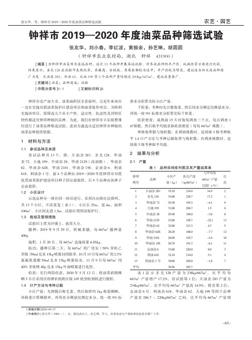
C-DIAS Analog Input Module CAI 022 2 x resistance measurement bridges ±2mV / VThe CAI 022 DMS module is used to record data fromresistance measurement bridges(e.g. load cells). With an 18-bit resolution, measurement values with an accuracy of±0,01% are available.Technical DataAnalog Channel SpecificationsNumber of channels 1 or 2Measurement range ±2 mV / VMeasurement value ±105000Resolution Internal 24 bit(From the 18 bit measurement value)Conversion time for all channels 8ms / 2 Channel drive4ms / 1 Channel driveBridge supply voltage 10VMaximum load of the voltagesupply (entire supply)135mAMaximum resistance per channel(using all 4 channels)150Ohm to 5000OhmAllowable resistance (parallelcircuit of all 4 bridges)75Ohm to 5000OhmAnalog channel measurement accuracy±0,01% of maximum measurement value (With an operating temperature from 0 to +40°C)Number of filters per channel 2 (1 fix, 2. 4-step settable)Serial interface Analysis with hyper terminal possible23.06.2006 Page1bSo that the maximum load for the reference voltage is not exceeded, a maximum of 4 bridges with a minimum resistance of 300 Ohms can be connected to the CAI 022. Here, it doesn’t matter if 4 bridges are connected parallel with one channel or if bothchannels are connected with 2 bridges.Step response of the analog and digital filters (20mV steps)10203040506070809010Samples [n]F i l t e r a u s g a n g [d e z i m a l ]Electrical RequirementsSupply from C-DIAS Bus +5V and +24VCurrent consumption of the C-DIAS Bus (+5 V supply) Typically 50mA Maximum 70mA Current consumption of the C-DIAS Bus (+5 V-supply)Typically 200mAMaximum 250mAIMPORTANT:This module exceeds the standard current consumption for C-DIAS modules!(+5V: 150mA and +24V: 150mA)If this C-DIAS module is mounted on an 8x module carrier (CMB 08x), the total current ofthe modules used must be determined and tested. Page 2 23.06.2006aThe specification for the current consumption is found in the technical document of therespective module under “Electrical Requirements”The total current of the +5V supply cannot exceed 1.2A (150mA/slot).This also applies to the total current of the +24V supply, which also cannot exceed1.2A (150mA/slot).3 23.06.2006 PageMiscellaneousArticle number 12-009-022Hardware version 1.xStandardization UL (E247993) in preparationEnvironmental conditionsStorage temperature -20 – +85°COperating temperature 0 – +40°CHumidity 0 – 95%, UncondensedEMV stability Per EN 61000-6-2:2001 (Industrial area)Shock resistance EN 60068-2-27 150m/s²Protection type EN 60529 IP 20Page 4 23.06.2006Mechanical Dimensions5 23.06.2006 PageTerminal AssignmentPage 6 23.06.2006 aX1: Measurement bridge 1X2: Measurement bridge 2 Pin Function 1 Signal input 1- 2 Signal input 1+ 3 Reference Input 1- 4 Reference Input 1+ 5 Reference Output 1- (GND) 6 Reference Output 1+ 7 Reference Output 1- (GND) 8 Reference Output 1+ 9 Earth connection 1 (shield) 10 Earth connection 1 (Shield)Pin Function 1 Signal input 2- 2 Signal input 2+ 3 Reference Input 2- 4 Reference Input 2+ 5 Reference Output 2- (GND) 6Reference Output 2+7 Reference Output 2- (GND) 8 Reference Output 2+ 9 Earth connection 2 (Shield) 10 Earth connection 2 (Shield)Pin Function 1 +5 V 2 Rx / TTL 3 Tx / TTL4 -5 GND 6-X3: Serial interfaceThe signals of the serial interfaces are TTL signals. To connect the serial interface to a RS232 interface a TTL/RS232 converter is necessary.23.06.2006 Page 7aApplicable ConnectorX1, X2: 10-pin Weidmüller connecter B2L3,5/10X3: 6-pin socket board RM2,54 (not included in connector set CKL 072!)The complete C-DIAS connector set CKL 072 with spring terminals is available fromSigmatek under the article number 12-600-072Page 8 23.06.2006Status DisplayLED Nr. LED color Description1 Green Output 1 DC OK2 Green Output 2 DATA9 23.06.2006 PageWiring GuidelinesGeneralThe 0V connection for the voltage supply must be wired to the 0V collection point over the shortest route possible.Wiring and Cable ShieldingThe analog signals received by the module are very small in comparison to the digital signals. To ensure error-free operation, a careful wiring method should be followed.The analog connection lines must be as short as possible and avoid parallel wiring with digital signal lines.The signal lines should be shielded or at the very least, twisted (see below).Page 10 23.06.2006C-DIAS ANALOG INPUT MODULECAI 022Wiring VariationsThere are two connection types available for measuring with the resistive wire strain: • 4-wire measurement: The advantage of this variation is that a four-pole connection cable can be used for the DMS; however, the voltage drop on the circuit for the bridge supply voltage cannot be compensated.Weidmüller PlugRLineJumperShieldingRLineMeasuring Bridge•6-wire measurement: This method has the advantage of voltage compensation through direct measurement of the bridge supply voltage on the DMS.Weidmüller PlugRLineShieldingRLineDMS-Measuring Bridge23.06.2006Page 11C-DIAS ANALOG INPUT MODULECAI 022Analysis of the serial interface with Hyper terminalSettings: Baud rate: Data bits: Parity: Stop bits: Flow control: 115,2k 8 None 1 NoneCounter:Shows how often measuring values are written to the serial interface. The measuring values are updated in about 9ms intervals. After each reset the counter reading is reset. This value corresponds to the filtered measurement value of the voltage on the resistor measuring bridge with 18-bit resolution. Filter frequency: fg = fSamp / 96Filter 1:Page 1223.06.2006C-DIAS ANALOG INPUT MODULE Filter 2:CAI 022This value corresponds to the filtered measurement value of the voltage on the resistor measuring bridge with 18-bit resolution. Filter frequency: fg = fSamp / x; x … [8, 16, 32, 64] The setting of the filter frequency for filter 2 takes place with the configuration register of the respective channel. The description of the configuration register can be found under Configuration register for Channel x – CFGRx.23.06.2006Page 13C-DIAS ANALOG INPUT MODULECAI 022Communication (C-DIAS)Over the C-DIAS bus, the operating parameters and data can be read and written. Up to 256, 8-bit addresses can be accessed. The data transfer is divided it two register groups. • • Status, instruction and configuration registers. Data registersNote: Registers not mentioned below cannot be used as they are used by the CAI022 internally. Data over the hardware can be read from the serial EEProm (LASAL EEProm) can be read.Status, instruction and configuration registersThese registers can be addressed directly.Data registersTo avoid bus conflicts between the controller and C-DIAS bus with 32-bit data transfers, the data are stored in 2 pages. A flag in STATUSR always points to the page with the most current values.Process for Reading Data from the C-DIAS BusThe control reads the PAGE bit in STATUSR. If this bit is cleared, the current data is stored in PAGE0. If the bit is set, the current data is in PAGE1. Data can be read from the actual page.Process for Writing Data from the CAI 022 µC.The µC reads the PAGE bit in STATUSR. If it is cleared, the data is written to PAGE1. If the PAGE bit is set, the data is written to PAGE0. The PAGE BIT is then inverted.Page 1423.06.2006C-DIAS ANALOG INPUT MODULECAI 022Schematic Process Diagram of Communication over the C-DIAS Bus.Data is read from PAGE00PAGE Bit in STATUSRControl reads Page indentificationµC of CAI022Data register PAGE0control reads from PAGE0C-DIASModule writes to PAGE1Data register PAGE123.06.2006Page 15C-DIAS ANALOG INPUT MODULE Data is read from PAGE1CAI 0221PAGE Bit in STATUSRControl reads Page identificationµC der CAI022Module writes to PAGE0Data register PAGE0C-DIASData register PAGE1Control reads from PAGE1Page 1623.06.2006C-DIAS ANALOG INPUT MODULECAI 022Registers used in Communication over the C-Dias BusRegister overviewRegister STATUSR CMDR CFG Description Module status (error messages, operating status) Instruction register (operating mode settings) Global configurations register Address 0x00 0x01 0x02VERFirmware version0x04 – 0x06CFGR1 CFGR2Configuration for channel 1 Configuration for channel 20x10 0x11SR1 SR2Error status for channel 1 Error status for channel 20x18 0x19DATA1_P0_F1 DATA1_P0_F2 DATA2_P0_F1 DATA2_P0_F2Data for filter output 1 Channel1 Page 0 Data for filter output 2 Channel1 Page 0 Data for filter output 1 Channel2 Page 0 Data for filter output 2 Channel2 Page 00x20 – 0x23 0x24 – 0x27 0x28 – 0x2B 0x2C – 0x2FDATA1_P1_F1 DATA1_P1_F2 DATA2_P1_F1 DATA2_P1_F2Data for filter output 1 Channel1 Page 1 Data for filter output 2 Channel1 Page 1 Data for filter output 1 Channel2 Page 1 Data for filter output 2 Channel2 Page 10x40 – 0x43 0x44 – 0x47 0x48 – 0x4B 0x4C – 0x4F23.06.2006Page 17C-DIAS ANALOG INPUT MODULECAI 022Status Register – STATUSRBit STAUSR R/W Initial Value 7 MOD3 R 0 6 MOD2 R 0 5 MOD1 R 0 4 MOD0 R 0 3 ERR R 0 2 R 0 1 R 0 0 PAGE R 0• • • • • •BIT 7 – MOD3: Modus Bit 3 See Mode bits table. BIT 6 – MOD2: Modus Bit 2 See Mode bits table. BIT 5 – MOD1: Modus Bit 1 See Mode bits table. BIT 4 – MOD0: Modus Bit 0 See Mode bits table. BIT 3 – ERR: Error Bit When this bit is set, an error has occurred. The error register should be checked. BIT 0 – PAGE: Page If this bit is cleared, the last valid data is stored in the address range 0x20 to 0x3F. If it is set, the last valid data is stored in the address range 0x40 to 0x5F. This flag is valid only in connection with the RDY bit.Mode bits tableMOD3 0 MOD2 0 MOD1 0 MOD0 0 Description Warm-up phase The module is in the warm-up phase. The data registers contain no valid data and no instruction can be sent except for the configuration mode. 0 0 0 1 Operating mode The module is in operating mode. The data registers now contain valid data.Page 1823.06.2006C-DIAS ANALOG INPUT MODULECAI 022Instruction Register - CMDRBit CMDR R/W Initial Value R/W 0 R/W 0 R/W 0 7 6 5 4 3 CMDR[7..0] R/W 0 R/W 0 R/W 0 R/W 0 R/W 0 2 1 0Instruction register for controlling the module. The module is set to 0 after this instruction is executed.Table of instructionsValue 0x01 0x02 Instruction Normal operation (Skip warm-up phase) Assume and save configurationsGlobal Configurations Register – CFGBit CFG R/W Initial Value R/W 0 R/W 0 R/W 0 R/W 0 R/W 0 R/W 0 7 6 5 4 3 2 1 CHAN1 R/W 0 0 CHAN0 R/W 0Global Configuration of CAI022 • • BIT1 – CHAN1 Channel configuration bit BIT0 – CHAN0 Channel configuration bitWith the CHAN1:CHAN0 bits, it is possible to select 1, 2 and 4-channel operation. The conversion time changes according to the settings.CHAN1 0 0 CHAN0 0 1 Number of channels (active channels) 1 (connector X1) 2 (connector X1 & X2) Conversion time for all channels 4ms 8ms23.06.2006Page 19C-DIAS ANALOG INPUT MODULECAI 022VER –Version registerBit VER0 VER1 VER2 R/W R R R R 7 6 5 4 VER[7..0] VER[15..8] VER[23..16] R R R R 3 2 1 0Version number of the Firmware: • • • VER[7..0] Revision number (binary) VER[15..8] Subversion number (binary) VER[24..16] Main version number (binary)Example:VER2 1 VER1 9 VER0 14 Version V01.09.14Configuration register for Channel x – CFGRxBit CFGRx R/W Initial Value 1 0 0 0 0 0 0 0 7 EN 6 5 4 3 2 1 FIL1 0 FIL0x...[1..4] • • BIT7-EN: Enable The channel is active when this bit is set and inactive when cleared. BIT1-FIL1: Filter selection for filter 2 See filter table • BIT0-FIL0: Filter selection for 2 See filter tablePage 2023.06.2006C-DIAS ANALOG INPUT MODULE CAI 022Filter tableFIL1 FIL0 Filter frequency for Filter 20 0 f g = f Samp / 8 Filter 2-10 1 f g = f Samp / 16 Filter 2-21 0 f g = f Samp / 32 Filter 2-31 1 f g = f Samp / 64 Filter 2-4Filter 1 (fixed value filter) has a filter frequency of f= f Samp / 96.gStatus register for Channel x – SRxBit 7 6 5 4 3 2 1 0SRx - - - - - - - SIGOFR/W R R R0 0 0 0 0 0 0 0ValueInitialx ... [1..4]• BIT 0 – SIGOV: Signal OverflowIf this bit is set, the measured value of the input signal is too high.When cleared, the measured value is within range.Data Register - DATAx_PyBit 7 6 5 4 3 2 1 0DATAx_Py_Fz DATAx_Py_Fz[7..0][15..8]DATAx_Py_Fz DATAx_Py_Fz[23..16]DATAx_Py_Fz DATAx_Py_Fz[31..24]DATAx_Py_Fz DATAx_Py_FzR/W R R R R R R R R0 0 0 0 0 0 0 0ValueInitialx ... [1 … 4], y ... [0, 1], z ... [1, 2]32 Bit Data register for channel x, page y and filter z.21 23.06.2006 PageC-DIAS ANALOG INPUT MODULE CAI 022LASAL EEProm DataCalibration data CAI022 (24C02 is organized by byte):Address Data Descriptionsum$00 $xx Check$01 123 Identification$02 5 Module group 5=CAI$03 10 Module version 4=CAI022$04 2 Number of channels$05 10 Hardware version $10=HW 1.0$06-$3F 0 FILLAI calibration datasum $40 $xxxx Check$42 12345 Identification$44 9 Length of the following data block in WORD$46 2 Number of channels$48-$57 …xxxxxx“ Serial number as 16-byte string. E.G.: …31333_01_0019___“$58-$AF 0 FILL$B0-$B3 xxx* Head1 (CalibrateCounter)$B4-$B7 xxx* Head1 (ZeroLevel)$B8-$BB xxx* Head1 (CalibrateLevel)$BC-$BF xxx* Head1 (CalibrateWeight)$C0-$C3 xxx* Head1 (MaxWeight)$C4-$D7 xxx* Head2 (partitioned the same as Head1)$D8-$EB xxx* Head3 (partitioned the same as Head1)$EC-$FF xxx* Head4 (partitioned the same as Head1)* Customer specific data (not require for the operatin of the module).Page 22 23.06.2006C-DIAS ANALOG INPUT MODULE CAI 02223 23.06.2006 Page。