4分齿轮流量计说明书(洗衣液))
Blue-White F-440系列流量计说明书

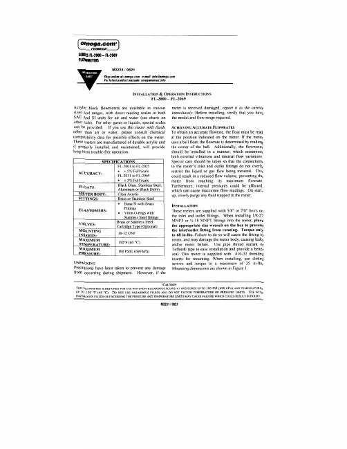
®Your Blue-White F-440 Series!®Your Blue-White flowmeter was designed to be easy to install.!Please read the Instruction Guideline on the next page before installing your flowmeter.!This flowmeter is an instrument, special care should be taken when handling and installing.Inspection of the Flowmeter and Compatibility!Carefully inspect the meter for any damage that may have occurred during shipping. !Remove the plastic tubing that has been inserted during packaging for shipping reasons.!Make sure your pressure, temperature, fluid and other requirements are compatible with the meter before installation.!The maximum temperature capability decreases as the pressure increases. The max PSI decreases as the temperature increases. See the chart on the following page. !®Although the meter may be suitable for other chemicals, Blue-White cannot guarantee their suitability. It is the responsibility of the user to determine the suitability of the flowmeter in their application. Flowmeters are tested and calibrated for water only.®!Blue-White warranties the flowmeter for use with water only.Meter Body: PolysulfoneFloat: 316SS, or PVDF (based on model)Guide rod: # 316 Stainless Adapters: PolysulfoneO-Rings: Viton (optional EP)Scale: Permanent, dual scale silkscreen (black ink)Max. PSIg: 175 PSIG / 12 BAR at 70°F/21°C Max. Temp: 212°F / 100°C at 0 pressure Accuracy: ± 4% of full scale readingpipe configuration, install the flowmeter after all glued fittings are dried and lines are purged of all fumes. Never hold the meter body with pliers or liketools. Union nuts should be hand tightened only. DO NOT OVER-TIGHTEN!3. Vibration and heavy loads will damage the meter!Wall, floor and ceiling mounts and supports must be carefully aligned with the meter body and sturdy enough to support the plumbing and prevent vibration. Never allow the flowmeter to support the weight of related piping.4. Solenoid valves will damage the meter!Avoid a system that will impose a sudden burst of flow to the meter . Such a burst will cause the float to impact the float stop with destructive force. Solenoid valves, or other quick opening valves cannot be used unless meter is protected against sudden bursts of flow.5. High pressures and temperatures will damage the meter!The maximum acceptable temperature and pressure is interdependent. Themaximum acceptable working pressure is dependant on the actual fluid tempera-ture. The maximum acceptable fluid temperature is dependant on the actual working pressure. (see Temperature Vs. Pressure chart).Installation Guideline90 p s i 6.2 b a r120 p s i 8.3 b a r150 p s i 10.3 b a rPressure and TemperaturePressure and temperature limits are inversely proportional. At the maximum suggested pressure the temperature should approach 70°F / 21.1°C; at the maximum suggested temperature the pressure should approach zero psi. We cannot guarantee our flowmeters will not be damaged either at or below thesuggested limits simply because of many factors which influence meter integrity; stress resulting from meter misalignment, damage due to excessive vibration and/or deterioration caused by contact with certain chemicals as well as direct sunlight. These situations and others tend to reduce the strength of the materials from which the meters are manufactured.Flowmeters are tested and calibrated for water only.Although meters may be suitable for other chemicals, Blue-Whitecannot guarantee their suitability. It is the responsibility of the user to determine the suitability of the flowmeter in their application.Application NoteTemperatureTemperature vs. Pressure90°F/32.2°C 70°F/21.1°C0 p s i 0 b a r30 p s i 2.1 b a r190°F/87.7°C 170°F/76.6°C 150°F/65.6°C 130°F/54.4°C 110°F/43.3°C 212°F/100°C 60 p s i 4.1b a rMaintenanceThe “Exploded View” drawing illustrates assembly of the F-440 series meter. If your flowmeter needs to be cleaned refer to this drawing when reassembling the unit. The tapered tube may be cleaned with a soft bottle brush. Use a MILD soap and water solution for cleaning purposes. Hard water deposits can be removed with a 5% acetic acid solution (vinegar). Note the floats “up” position.175 p s i 12 b a rF-440 - In-Line2147511 65412Part No. Desc.F-44N07 3/8” Male NPT in-line adapter, PolysulfoneF-44N08 1/2” Male NPT in-line, PolysulfoneF-44N09 3/4” Male NPT in-line, PolysulfoneF-45N013 ½” Male NPT in-line, Polysulfone, large body F-44N05 3/8” and 1/2” Half Union, NylonF-44N06 3/4” Half Union, Nylon90003-152 3/8” and 1/2” O-ring seal, Viton90003-627 3/8” and 1/2” O-ring seal, EP90003-082 3/4” O-ring seal, Viton90003-039 3/4” O-ring seal, EPN/A Meterbody and Float not sold separatelyF-44N14 3/8” and 1/2” Guide Rod, 316 Stainless SteelF-44N15 3/4” Guide Rod, 316 Stainless SteelF-45N007 3/8” and ½”Guide Rod holder, PolysulfoneF-45N019 3/4” Guide Rod holder, PolysulfoneF-45N043 Indicator, RedNo.124567711F-440E - Elbow (Panel Mount)116574123754123No.Part No.Description1F-44N403/8” Male NPT 90° Elbow, Polysulfone F-44N201/2” Male NPT 90° Elbow, Polysulfone F-44N213/4” Male NPT 90° Elbow, Polysulfone F-44N421/2” Male NPT 90° Elbow, Polysulfone 2F-44N053/8” and 1/2” Half Union, Nylon F-44N063/4” Half Union, Nylon3F-4427A 3/8” and 1/2” Panel mount lock nut F-4428A 3/4” Panel mount lock nut 490003-1523/8” and 1/2” O-ring seal, FKM90003-6273/8” and 1/2” O-ring seal, EP 90003-0823/4” O-ring seal, FKM 90003-0393/4” O-ring seal, EP5N/A Meterbody / Float (not sold separately)6F-44N143/8” & 1/2” Guide Rod, 316 SSF-44N153/4” Guide, 316 SS7F-45N0073/4” Guide Rod, Hastelloy C-276F-45N0193/4” Guide Rod holder, Polysulfone11F-45N043Indicator, RedF-440A - Adjustable (Panel Mount)1154265748731109F-440A - Adjustable (Panel Mount) No.Part No.Description1F-44N403/8” Male NPT 90° Elbow, Polysulfone F-44N201/2” Male NPT 90° Elbow, Polysulfone F-44N213/4” Male NPT 90° Elbow, Polysulfone F-44N421/2” Male NPT 90° Elbow, Polysulfone2F-44N053/8” and 1/2” Half Union, Nylon F-44N063/4” Half Union, Nylon3F-4427A3/8” and 1/2” Panel mount lock nut F-4428A3/4” Panel mount lock nut490003-1523/8” and 1/2” O-ring seal, FKM 90003-6273/8” and 1/2” O-ring seal, EP 90003-0823/4” O-ring seal, FKM90003-0393/4” O-ring seal, EP5N/A Meterbody and Float (not sold separately)6F-44N143/8” & 1/2” Guide Rod, 316 SS F-44N153/4” Guide, 316 SS7F-45N0071/2” Guide Rod holder, Polysulfone F-45N0193/4” Guide Rod holder, Polysulfone8F-44N40-13/8” M/NPT Valve Assm. Sm, Poly, FKM seal F-44N40-21/2” M/NPT Valve Assm. Sm, Poly, FKM seal F-45N031-13/8” M/NPT Valve Assm. Lg, Poly, FKM seal F-45N031-21/2” M/NPT Valve Assm. Lg, Poly, FKM seal F-45N031-33/4”” M/NPT Valve Assm. Lg, Poly, FKM seal990003-010O-Ring, FKM 90003-597O-Ring, EP1090003-071O-Ring, FKM 90003-018O-Ring, EP11F-45N043Indicator, RedURL: E-mail:**************************************************Phone: 714-893-8529 Fax: 714-894-0149BLUE-WHITE LIMITED WARRANTYYour Blue-White product is a quality product and is warranted for a specific time from date of purchase (proof of purchase is required). The product will be repaired or replaced at our discretion. Failure must have occurred due to defect in material or workmanship and not as a result of operation of the product other than in normal operation as defined in the product manual. Warranty status is determined by the product's serial label and the sales invoice or receipt. The serial label must be on the product and legible. The warranty status of the product will be verified by Blue-White or a factory authorized service center.Variable Area and Digital Flow meters are warranted for 1 year from date of purchase (proof of purchase is required). The flow meter will be repaired or replaced at our discretion. The S6A ultrasonic flow meter is warranted for 2 years from date of purchase (proof of purchase is required). The flow meter will be repaired or replaced at our discretion.WHAT IS NOT COVERED• Freight to the factory, or service center.• Products that have been tampered with, or in pieces.• Damage resulting from misuse, carelessness such as chemical spills on the enclosure, abuse, lack of maintenance, or alteration which is out of our control.• Damage by faulty wiring, power surges or acts of nature.• Damage that occurs as a result of: meter misalignment, improper installation, over tightening, use of non- recommended chemicals, use of non-reccomended adhesives or pipe dopes, excessive heat or pressure, or allowing the meter to support the weight of related piping.BLUE-WHITE does not assume responsibility for any loss, damage, or expense directly or indirectly related to or arising out of the use of its products. Failure must have occurred due to defect in material or workmanship and not as a result of operation of the product other than in normal operation as defined in the manual.Warranty status is determined by the product's serial label and the sales invoice or receipt. The serial label must be on the product and legible. The warranty status will be verified by Blue-White or a factory authorized service center. PROCEDURE FOR IN WARRANTY REPAIRWarranty service must be performed by the factory or an authorized service center. Contact the factory or local repair center to obtain a RMA (Return Material Authorization) number. It is recommended to include foot strainer and injection/check valve fitting since these devices may be clogged and part of the problem. Decontaminate, dry, and carefully pack the product to be repaired. Please enclose a brief description of the problem and proof of purchase. Prepay all shipping and insurance cost. COD shipments will not be accepted. Damage caused by improper packaging is the responsibility of the sender. When In-Warranty repair is completed, the factory pays for return shipping to the dealer or customer.PRODUCT USE WARNINGBlue-White products are manufactured to meet the highest quality standards in the industry. Each product instruction manual includes a description of the associated product warranty and provides the user with important safety information. Purchasers, installers, and operators of Blue-White products should take the time to inform themselves about the safe operation of these products. In addition, Customers are expected to do their own due diligence regarding which products and materials are best suited for their intended applications. BLUE-WHITE is pleased to assist in this effort but does not guarantee the suitability of any particular product for any specific application as Blue-White does not have the same degree of familiarity with the application that the customer/end user has. While BLUE-WHITE will honor all of its product warranties according to their terms and conditions, Blue-White shall only be obligated to repair or replace its defective parts or products in accordance with the associated product warranties.BLUE-WHITE SHALL NOT BE LIABLE EITHER IN TORT OR IN CONTRACT FOR ANY LOSS OR DAMAGE WHETHER DIRECT, INDIRECT, INCIDENTAL, OR CONSEQUENTIAL, ARISING OUT OF OR RELATED TO THE FAILURE OF ANY OF ITS PARTS OR PRODUCTS OR OF THEIR NONSUITABILITY FOR A GIVEN PURPOSE OR APPLICATION.CHEMICAL RESISTANCE WARNINGBLUE-WHITE offers a wide variety of wetted parts. Purchasers, installers, and operators of Blue-White products must be well informed and aware of the precautions to be taken when injecting or measuring various chemicals, especially those considered to be irritants, contaminants or hazardous. Customers are expected to do their own due diligence regarding which products and materials are best suited for their applications, particularly as it may relate to the potential effects of certain chemicals on Blue-White products and the potential for adverse chemical interactions. Blue-White tests its products with water only. The chemical resistance information included in this instruction manual was supplied to BLUE-WHITE by reputable sources, but Blue-White is not able to vouch for the accuracy or completeness thereof. While BLUE-WHITE will honor all of its product warranties according to their terms and conditions, Blue-White shall only be obligated to repair or replace its defective parts or products in accordance with the associated product warranties.BLUE-WHITE SHALL NOT BE LIABLE EITHER IN TORT OR IN CONTRACT FOR ANY LOSS OR DAMAGE, WHETHER DIRECT, INDIRECT, INCIDENTAL, OR CONSEQUENTIAL, ARISING OUT OF OR RELATED TO THE USE OF CHEMICALS IN CONNECTION WITH ANY BLUE-WHITE PRODUCTS.Users of electrical and electronic equipment (EEE) with the WEEE marking per Annex IV of the WEEE Directive must not dispose of end of life EEE as unsorted municipal waste, but use the collection framework available to them for the return, recycle, recovery of WEEE and minimize any potential effects of EEE on the environment and human health due to the presence of hazardous substances. The WEEE marking applies only to countries within the European Union (EU) and Norway. Appliances are labeled in accordance with European Directive 2002/96/EC. Contact your local waste recovery agency for a Designated Collection Facility in your area.80000-440 REV. 3 20230327。
ZHM中文操作手册

Küppers Elektromechanik GmbHFlow MetersLiebigstraße 2 • D-85757 Karlsfeld • Tel.+49 81 31/59 39 10 • Fax +49 81 31/9 26 04ZHM系列安装和操作手册综述齿轮流量计是容积式流量计,结构与齿轮泵相似。
随着介质的流动,推动两个互相啮合的齿轮转动。
介质从齿轮和壳体之间的测量室流过。
一对齿轮自由转动,不需要供电。
齿轮的转速与瞬时流量成正比。
齿轮流量计配备了信号拾取传感器,不用接触介质而透过外壳就可以精确检测转速。
每单位体积的脉冲数是固定的,从而可以计算体积流量。
另外,如果选用了带内置传感器的现场指示表头VTM,还可以提供4到20mA模拟信号输出。
计算 齿轮流量计的K-系数(标定系数)精确定义了每升流量的输出脉冲数。
每台表出厂时都 提供一份标定记录,可以得到K-系数。
另外,我们的标定记录还提供以下信息:•折合到瞬时流量的最大测量误差• 相应流量范围的最大/最小频率•不同流量时的K-系数•整个流量范围有效的平均 K-系数应用以下公式:Q=流量,单位为升每分钟f= 输出脉冲频率,单位为 Hz=齿轮流量计的K-系数,单位为脉冲每升准备工作机械和电路安装、调试和维护必须由合格或者认可的人员进行。
请保证ZHM的测量范围不能够超过规定值的20%。
安装以前测量管道应当进行清洁。
颗粒和杂质一定不能进入流量计,因为可能造成堵塞。
尤其是对于小口径的ZHM01-ZHM02更加重要。
对于以下介质请使用过滤器作为预防:ZHM01–03:120 微米04–05:200 微米06–07:300 微米流量计的安装齿轮流量计应当按照流量方向(标定方向)安装。
可以水平也可以垂直安装。
流量方向在表体上用箭头指示。
对于有反向流量的测量安装方向没有关系,因为这种情况下流量计两个方向都做过标定。
我们的标准型齿轮流量计适合Ermeto螺纹连接件,不需要其它的额外密封。
椭圆齿轮流量计说明书

LC型椭圆齿轮流量计使用说明书目录一、概述 (1)二、技术性能特点 (1)三、工作原理 (2)四、连接方式 (3)五、调试与使用 (3)六、安装与使用注意 (5)七、型号表示方法 (6)八、开箱注意事项 (7)九、订货须知 (7)LC椭圆齿轮流量计一、概述我们具有独立的产品设计、制造体系,能够提供多种材料、口径和连接方式,还提供与之相配套的转换器、显示仪表和流量计算机等。
椭圆齿轮流量计的工作原理是液体推动一对椭圆齿轮转动;每个腔体的容积是固定体积;齿轮转速引出,传感器发出同步脉冲计数,椭圆齿轮的转动通过磁性密封联轴器及传动减速机构传递给计数器直接指示出流经流量计的总量。
若附加发信装置后,再配以电显示仪表,可实现远传只是瞬时流量和累积流量。
典型应用:椭圆齿轮流量计主要用于测量高粘度的介质,产品广泛应用于石油、石化、天然气、化工、造纸等行业,用于测量小管径的微小流量计量。
主要优点:◆口径从10~150mm;◆外壳材质有多种供选择:铝、不锈钢及中高压不锈钢、PPS、青铜等;◆轴承材质有多种供选择:陶瓷、青铜、哈氏合金、碳化物、PPS、不锈钢等;◆轴的材质:316不锈钢;◆ O形环的材质有VITON、氟橡胶、不锈钢、特氟隆供选择;◆量程比10:1,最大可达50:1;◆精度为±1%和±0.5%两种,重复性±0.03%;◆安装时直管段要求:5D+3D,需加装过滤器;◆粘度最高可达1,000 000CP;◆压力等级最高可达551bar;◆耐温等级最高可达-10~80℃;二、技术性能特点1. 椭圆齿轮流量计的技术性能型号 口径 最小流量 最大流量 精度等级工作压力(Mpa )LC —8 8 0.04 0.4 0.5,0.21.6,2.5,4.0,6.4LC —15 15 0.16 1.5 LC —20 20 0.3 3 LC —25 25 0.6 6 LC —40 40 1.5 15 LC —50 50 2.4 24 LC —80 80 6 60 LC —100 100 10 100 LC —150150121202.椭圆齿轮流量计的特点流量测量与流体的流动状态无关,这是因为椭圆齿轮流量计是依靠被测介质的压头推动椭圆齿轮旋转而进行计量的。
全流量多点齿轮分流器中文说明书C

全流量多点齿轮分流器(用于静压轴承、静压导轨上)
产品介绍
武汉樵薪机械制造有限公司
技术规格书
一、产品简介
武汉樵薪机械制造有限公司出品的全流量多点齿轮分油器,每个出油口均有一对齿轮组成的分油器均分全流量供油,只要油腔压力在油泵与分油器的范围以内,一定能使相对滑动面脱离接触形成液体摩擦。
故压力储备大,过载能力强。
其次,系统中没有阻尼。
不会因堵塞使油腔失压,故可靠性好。
其三,没有调整环节,且系标准部件,设计、装配、维修方便。
系统工作原理如图:
1.可用变量泵供油,流量无级调整。
2.可以用定量油泵全流量工作,在稳定油泵供油压力或限制最高压力下工作。
建议:在负载变化大的静压系统中,静压油源采用两套定量,轻载时启动小排量前给泵,中载时启动大排量前给泵,满载时两套前给泵同时启动。
用全流量多点齿轮分油器供油的静压系统,可用于立车工作台静压导轨,大型车床主轴,工件托架,轧辊磨床砂轮轴,滚齿机花盘定心轴等的静压轴承,机床与机器上其它静压轴承,以及静压蜗杆蜗母条传动副等。
在静压导轨系统中,静压导轨上的油腔多时,可用几套独立的系统联合供油;在静压主轴系统中,静压轴承的油腔少,一套系统可以供二个或三个轴承。
油腔的流量大时,可用二个或几个出油点并联供油;也可以将几套系统的相应出油点并联作为一套系统用。
本全流量多点齿轮分油器适用50—200厘拖的机械油。
最大油腔力为50公斤力/厘米。
可用飞轮蓄能作断电保护。
常用的几种多点齿轮分油器尺寸与适用范围如下:
外观图。
流量计仪表操作说明

目录仪表的键盘和前面板-------------------------------------2 仪表功能----------------------------------------------------4 仪表程序----------------------------------------------------4 仪表键盘和中控方式的转换----------------------------6 仪表的启动和停止----------------------------------------7 仪表重量和容积方式的转换----------------------------8 给定量的输入----------------------------------------------8 显示事件信息----------------------------------------------8 服务数据----------------------------------------------------9 标定功能----------------------------------------------------9 调零-----------------------------------------------------14 计数器1或2的复位-------------------------------------13 安装与调整-------------------------------------------------13 维护与保养-------------------------------------------------14 事件信息----------------------------------------------------16(一)仪表的键盘1各按键的作用如下:启动键和停止键。
eyc-tech DPM04流量计总计器用户手册说明书
Manuals+— User Manuals Simplified.eyc-tech DPM04 Flow Totalizer User ManualHome » eyc-tech » eyc-tech DPM04 Flow Totalizer User Manualeyc-tech DPM04 Flow TotalizerContents1 Security Considerations2 Dimension3 Connection4 Installation5 Configuration Software5.1 Application ProgramIntroduction5.2 Establish RS-485 connection5.3 Scan RS-485 connection5.4 Setting RS-485 ModBus Protocol5.5 Measurement Programming5.6 Linearity Computation5.7 Export and Import Configuration5.8 Device Information5.9 Totalizer5.10 Display and Data Log6 Menu Operation6.1 Menu Flowchart7 Inspection And Maintenance7.1 Maintenance7.2 Troubleshooting8 Customer Support9 Documents / Resources9.1 References10 Related PostsSecurity ConsiderationsPlease read this Specification carefully, prior to use of this, and keep the manual properly,for timely reference.Solemn StatementThis product can not be used for any explosion-proof area.Do not use this product in a situation where human life may be affected.eyc-tech will not bear any responsibility for the results produced by the operatorsWarning!Installation and wiring must be performed by qualified personnel in accordance with all applicable safety standards.This product must be operated under the operating conditions specified in manual to prevent equipment damages.Please using the product under the ordinary pressure, or it will influence safe problem.This product must be operated under the operating condition specified in this manual to prevent equipment damages.This product must be operated under the normally atmospheric condition to prevent equipment damages.To prevent products damage, always disconnect the power supply from the product before performing any wiring and installation.All wiring must comply with local codes of indoor wiring and electrical installation rules.Please use crimp type terminal.To prevent personal injury, do not touch the moving part of product in operation.Installation Dimension InstallationConfiguration SoftwareApplication Program IntroductionUser may download the configuration software on eyc-tech web site. Please decompress the application prior to execute it. Operating System requirements:above Windows 7 SP1. Other application program requirements: above Microsoft Office 2003. Hardware requirements: USB to RS-485 converter.Establish RS-485 connection1. Connect product to PC via RS-485 converter2. Execute configuration software3. Click “Interface > Config”4. Select the corresponding values of com port as following :a. Port: Please confirm the connection com port firstb. Baud Rate (DPM04 default 9600)c. Data Frame (device default None Parity Check, 8 data bits, 1 stop bit)d. Response Timeout (default 300ms)e. Retry, trial cycles if communication error (default 2 times)f. Station ID (default 1)5. Click “Apply”6. Connect successfullya. Show value and trend chart of the measurementb. Show value and tread chart of device mcu temperaturec. Show “Open Port, Read successful”Scan RS-485 connection※Use scan function to connect when forgetting the connection information or having more facilities.1. Connect the product to PC via RS-485 converter2. Execute configuration software3. Click “Interface > Config”4. Select the corresponding values of com port as fallowing5. Click “Scan” to execute connection facilities6. Scan connection facilities and set upa. Select Station IDb. Click “CLOSE AND EXPORT”7. Click “Apply”8. Connect successfullya. Show value and trend chart of the measurementb. Show value and tread chart of device mcu temperaturec. Show “Open Port, Read successfulSetting RS-485 ModBus Protocol1. Setting RS-485 connection as step 5.12. Click “Setting” tab3. Select Modbus Protocol parametera. Station ID 1~247b. Baud Rate 9600, 19200, 38400, 57600, 115200c. Data Frame None-8Bit-1Stop, None-8Bit-2Stop, Even-8Bit-1Stop,Even-8Bit-2Stop, Odd-8Bit-1Stop, Odd-8Bit-1StopMeasurement ProgrammingClick the “Configuration” tab, the configuration divide by 4 sub groups as following.1. 1. Input function, this function could be found in “Input” taba. Input type, current, voltage, frequency, pulse or modbusb. Number of input rate decimal places, up to 4c. Low point of input spand. High point of input spane. volume unit of input ratef. period unit of input rateg. Analog input range (valid when the input selects current)h. Analog input range (valid when the input selects voltage)i. Low point of frequency input (valid when the input selects frequency)j. High point of frequency input (valid when the input selects frequency)k. value of pulse input (valid when the input selects pulse)l. unit of pulse input (valid when the input selects pulse) The following input is valid when 485 is selected m. Modbus protocol type, master or slavern. station IDo. Baud rate (valid when the input selects the master node)p. Parity checkq. Stop bitr. Register addresss. Register data typet. Data format, data word high and low exchangeu. Numerical magnificationThe flow totalizer setting itemsv. Number of decimal placesw. volume unitx. duct profile area (valid when velocity to volume conversion)y. flow coefficient (valid when velocity to volume conversion)2. Output function, this function could be found in “Output” taba. output type, current or voltageb. analog output range (valid when the output selects current)c. analog output range (valid when the output selects voltage)d. low point of output spane. high point of output spanf. error reaction, force current output if error detected. Select None if function disable. (valid when the outputselects current)g. linear correction, Off if disable, Interpolation if linear interpolation, Square Root if root extractionh. output cut-off, disable if set 0i. response time, e.g. set 3.0 if take 3.0 seconds for rise time T903. Relay function, this function could be found in “Relay” taba. driven signal source, rate or totalizerb. set pointc. action mode, HI.AL if upscale active, LO.AL if downscale actived. hysteresise. alarm, NONE if disable, HOLD if memory and hold the first alarm until reboot, Action if active when alarmassert, Deaction if inactive when alarm assertf. relay on delay time (seconds)g. relay off delay time (seconds)4. The other items could be found in “Option” taba. LED brightness, 0 darkest, 9 brightestb. password validation, NO if disable, YES is enablec. new passwordd. pause counter of volume accumulatione. reset factory default (without counter of totalizer)Linearity ComputationClick the Interpolation tab to specify the linear interpolation pointsa. interpolation tableb. interpolation curvec. Interpolate input column, device measured value (raw value)d. Interpolate output column, device output value (standard value or correction value)e. Read the interpolation table of the devicef. Clear the interpolation table on configuration software. Note: this action will not modify the interpolation table of the deviceg. apply, the interpolation would be written in deviceExport and Import ConfigurationClick the Setting tab to export and import device configurationa. summary text of device configurationb. read device configurationc. write device configurationd. load device configuratione. save device configurationexport procedure: device connection → step b→ step eimport procedure: device connection→ step d → step cDevice InformationClick the Information tab to get device informationa. device serial numberb. device model namec. firmware versiond. factory mode enabled statee. firmware checksumf. RS-485 enabled stateg. input function enabled stateh. output function enabled statei. totalizer enabled state input calibration information j. analog current input calibration pointsk. analog voltage input calibration pointsl. frequency input calibration pointsOutput calibration informationm. analog voltage output calibration pointsn. analog current output calibration pointso. Calibration dateTotalizerClick the Totalizer tab to display the volumetric accumulation and related functiona. instantaneous flow rate, programmable unitb. instantaneous flow rate, unit of Liter/minc. accumulative flow, unit conversion 1, default m3d. accumulative flow, unit conversion 2, default Litere. unit of accumulative flow 1f. unit of accumulative flow 2g. master enable of volumetric accumulationh. enable of accumulation 1i. enable of accumulation 2j. reset button of accumulation 1k. reset button of accumulation 2Display and Data LogClick the Display tab to display the measurement data and start data log function1. data display: click the “Display” tab2. button descriptionclear the plot charttoggle chart plotting line styleselect the OUTPUT channel you want to setset the line color of the selected OUTPUT channelsnap the currently chart plotexport data log since device is connectedaxis Y main coordinate, ON or OFFaxis X coordinate, ON or OFFaxis Y secondary coordinate, ON or OFFlegend, ON or OFFmeasurement data logging, ON or OFFaxis X time scaleaxis Y amplitude scale3. Set the logging time intervala. Click File > Log Intervalb. select the logging interval4. Store/log measurement datastore measurement data: save the logging data since device is connected click Display > Exportspecify the path and filename > SaveNote: If the specified path and file name are the same, the original file data will be over written log measurement data: start data loggingclick Display > Log(OFF)specify the path and filename > saveNote: If the specified path and file name are the same, the original file data will be over written. Menu OperationButton name and locationDPM status and button functionButton InstructionDPM ModeNormal Mode Menu ModePress UP once Reserved increase number or option oncePress OK once Go Menu Mode Submit the selection, go on next menu or complete the setting and then return to the normal modePress DOWN once Reserved decrease number or option once, shift cursot if numerical me nuHold UP Reserved increase number or option fasterHold OK 1.5 seconds Reserved Return to previous menu, or leave menu mode Hold DOWN Reserved decrease number or option fasterPress UP and DOWN simultaneouslyReset Counter Not AvailableMenu Flowcharteyc-tech DPM04 Menu Flowcharteyc-tech DPM04 Menu FlowchartInspection And MaintenanceMaintenanceSince this product is inspected and calibrated for high accuracy at the factory before shipment, no calibration on the installation site is necessary when this product is installed. For inspection and maintenance follow the instructions below:Periodically inspect this product for its sensing accuracy. Set the period between inspections based on operating temperature, dust content and dirt condition of the place of installation, and regular calibration is carried out to guarantee the accuracy.TroubleshootingIf abnormality occurs during operation, please check and repair according to the following table and takenecessary handling.eyc-tech DPM04 Flow Totalizer [pdf] User ManualDPM04 Flow Totalizer, DPM04 Flow Totalizer, Flow Totalizer, TotalizerReferenceseyc-tech|Taiwan measurement specialist, sensor manufacturerManuals+,。
流量计说明书.pdf_1718715200.0919275

TABLE OF CONTENTS Introduction (4)Specifications (6)Installation (7)Operational Start-Up (9)Troubleshooting (11)Flow Monitor Information (12)Repair Kit Information (13)Statement of Warranty (15)INTRODUCTIONFluid entering the meter passes through the inlet flow straightener which reduces its turbulent flow pattern and improves the fluid’s velocity profile. Fluid then passes through the turbine blades causing it to rotate at a speed proportional to the fluid velocity. As each blade passes through the magnetic field, created at the base of the pickoff transducer, AC voltage (pulse) is generated in the pick-up coil (see Figure 1). These impulses produce an output frequency proportional to the volumetric flow through the meter. The output frequency is used to represent flow rate and/or totalization of fluid passing through the turbine flow meter.FIGURE 1Schematic illustration of electric signalgenerated by rotor movementTURBINE METERThe FTB-1400 Series Turbine Flow Meter is designed to withstand the rigorous demands of the most remote flow measurement applications. The FTB-1400 Series Flow Meter maintains measurement accuracy and mechanical integrity in the corrosive and abrasive fluids commonly found in oil field waterflood project pipelines, in-situ mining operations, offshore facilities and plant locations. Simple to install and service, it can operate in any orientation (horizontal to vertical) as long as the“flow direction” arrow is aligned in the same direction as the actual line flow. For optimum performance, the flow meter should be installed with a minimum of 10 diameters upstream pipe length and 5 diameters downstream pipe length.FIGURE 2Typical cross-section of FTB-1411 throughFTB-1441 turbine flow meterSPECIFICATIONSMATERIALS of CONSTRUCTION: Body : 316 Stainless SteelRotor : CD4MCU Stainless SteelRotor Support and Bearings : 316 Stainless SteelRotor Shaft : Tungsten CarbideOPERATING LIMITATIONS:Temperature: -150 °F to +350 °F (-101 °C to +177 °C) The metershould not be subjected to temperatures above +350° F(177° C), or below -150° F (-101° C) or the freezingpoint of the metered liquid. High temperatures willdamage the magnetic pick-up, while lower temperatureswill limit the rotation of the rotor.Pressure : Maximum pressure ratings as follows:5,000 psi ─ all NPT meters up to 2"2,000 psi ─ 3" male NPT1,500 psi ─ 4" male NPT1,000 psi ─ 6" male NPT800 psi ─ all grooved end metersNote: Consult factory for pressure ratings for flanged meters. Accuracy:± 1.0% of reading Repeatability: ± 0.1%Calibration: Water (NIST Traceable Calibration) Corrosion: All FTB-1400 series turbine meters are constructed ofstainless steel and tungsten carbide. The operator mustensure that the operating fluid is compatible with thesematerials. Incompatible fluids can cause deterioration ofinternal components and cause a reduction in meteraccuracy.Pulsation andVibration: Severe pulsation and mechanical vibration will affectaccuracy and shorten the life of the meterFiltration: If small particles are present in the fluid, it is recommendedthat a strainer be installed upstream of the meter (see Table 1 WARNING: Pressure in excess of allowable rating may cause the housing to burst and cause serious personal injury.FLOW MONITOR:For a complete flow monitor package, Omega offers the FTB-1400 Series Flow Monitors (see Appendix B on page 12 for flow monitor information). These digital signal processing displays utilize the low-level frequency input from the FTB-1400 Series Turbine Meters to calculate flow rate and total. When ordered with an Omega FTB-1400 Series Turbine Meter, the included factory calibration will provide dependable and accurate flow information.REPAIR KIT:The FTB-1400 Series Turbine Meter Repair Kit is designed for easy field service of a damaged flow meter, rather than replacing the entire flow meter (see Appendix B on page 12 for repair kit information).Repair parts are constructed of stainless steel alloy and tungsten carbide and are factory calibrated to ensure accuracy throughout the entire flow range. Each kit is complete and includes the calibrated K-factor which is used to recalibrate the flow monitor or other electronics to provide accurate output data.INSTALLATION INSTRUCTIONSPrior to installation, the flow meter should be checked internally for foreign material and to ensure the turbine rotor spins freely. Fluid lines should also be checked and cleared of all debris.The flow meter must be installed with the flow arrow, etched on the exterior of the meter body, pointing in the direction of fluid flow. Though the meter is designed to function in any position it is recommended, where possible, to install horizontally with the magnetic pick-up facing upward.The liquid being measured should be free of any large particles that may obstruct rotation of the rotor. If particles are present, a mesh strainer should be installed upstream before operation of the flow meter. (See Table 1 on page 8.)TABLE 1 Strainer Mesh Installation DetailsThe preferred plumbing setup is one containing a by-pass line (Figure 3 on page 10) that allows meter inspection and repair without interrupting flow. If a by-pass line is not utilized, it is important that all control valves be located downstream of the flow meter (Figure 4 on page 10).This is true with any restriction in the flow line that may cause the liquid to flash. If necessary, air eliminators should be installed to ensure that the meter is not incorrectly measuring entrained air or gas.PARTNUMBER STRAINER MESH CLEARANCE FILTER SIZE FTB-1411, FTB-142160 × 60 .0092 260 Micron FTB-1412, FTB-142260 × 60 .0092 260 Micron FTB-1413, FTB-142360 × 60 .0092 260 Micron FTB-142460 × 60 .0092 260 Micron FTB-1425 60 × 60 .0092 260 MicronFTB-1431 20 × 20 .0340 .86mm FTB-1441 20 × 20 .0340 .86mmCAUTION: Damage can be caused by striking an empty meter with a high velocity flow stream.It is recommended that a minimum length, equal to ten (10) pipe diameters of straight pipe, be installed on the upstream side and five (5) diameters on the downstream side of the flow meter. Otherwise, meter accuracy may be affected. Piping should be the same size as the meter bore or threaded port size.Do not locate the flow meter or connection cable close to electric motors, transformers, sparking devices, high voltage lines, or place connecting cable in conduit with wires furnishing power for such devices. These devices can induce false signals in the flow meter coil or cable, causing the meter to read inaccurately.If problems arise with the flow meter and monitor, consult Appendix A (Troubleshooting Guide) on page 11. If further problems arise, consult the factory.If the internal components of the turbine flow meter are damaged beyond repair, turbine meter repair kits are available. Information pertaining to the turbine meter repair kits is referenced in Appendix B on page 12.OPERATIONAL START-UPThe following steps should be followed when installing and starting the meter.WARNING: Make sure that fluid flow has been shut off and pressure in the line released before attempting to install the meter in an existing system.1. After meter installation, close the isolation valves and open theby-pass valve. Flow liquid through the by-pass valve for sufficient time to eliminate any air or gas in the flow line.CAUTION: High velocity air or gas may damage the internal components of the meter.2. Open upstream isolating valve slowly to eliminate hydraulic shockwhile charging the meter with the liquid. Open the valve to full3. Open downstream isolating valve to permit meter to operate.4. Close the by-pass valve to a full closed position.5. Adjust the downstream valve to provide the required flow ratethrough the meter. Note: The downstream valve may be used as a control valve.FIGURE 3Meter installation utilizing a by-pass line(Shown with an FTB-1400 Series Flow Monitor)FIGURE 4Meter installation without utilizing a by-pass lineAPPENDIX ATROUBLESHOOTING GUIDE Trouble Possible Cause RemedyMeter indicates higher than actual flow rate -Cavitation-Debris on rotor support-Build up of foreign materialon meter bore-Gas in liquid-Increase back pressure-Clean meter-Clean meter-Install gas eliminatorahead of meterMeter indicates lower than actual flow rate -Debris on rotor-Worn bearing-Viscosity higher than calibrated-Clean meter and add filter-Clean meter and add filter-Recalibrate monitorErratic system indication, meter alone works well (remote monitor application only) Ground loop in shielding Ground shield one placeonly. Look for internalelectronic instrumentground. Reroute cablesaway from electrical noiseIndicator shows flow when shut off Mechanical vibration causesrotor to oscillate without turningIsolate meterNo flow indication. Full or partial open position Fluid shock, full flow into drymeter or impact caused bearingseparation or broken rotor shaftRebuild meter with repairkit and recalibrate monitor.Move to location wheremeter is full on start-up oradd downstream flowcontrol valveErratic indication at low flow, good indication at high flow Rotor has foreign materialwrapped around itClean meter and add filterNo flow indication Faulty pick-up Replace pick-upSystem works perfect, except indicates lower flow over entire range By-pass flow, leak Repair or replace by-passvalves, or faulty solenoidvalvesMeter indicating highflow, upstream pipingat meter smaller thanmeter boreFluid jet impingement on rotor Change pipingOpposite effects of above Viscosity lower than calibrated Change temperature,change fluid or recalibratemeter11APPENDIX BFTB-1400 SERIES FLOW MONITOR Simplified Version• Displays rate and/or total• Large 8 digit by 3/4” display• Front panel programming• NEMA 4X enclosure• Five selectable units of measure• Programs in seven simple stepsPart Number InformationFTB 1400 X DMounting StyleM = Meter MountR =Remote MountS =Swivel Mount Advanced Version• Displays rate and/or total• Large 8 digit by 3/4” display• Front panel programming• NEMA 4X enclosure• Thirteen selectable units of measure• Selection of time intervals for rate measurement• Ten point linearization• Provides additional programming optionsPart Number InformationFTB 1400 X D AMounting StyleM = Meter MountR =Remote MountS =Swivel Mount1213FTB-1400 REPAIR KITFigure 5Typical turbine meter component directoryFlow Meter SizeRepair Kit FitsMeter Part NumberRepair KitPart Number3/8" FTB-1411,FTB-1421 FTB-1400A-RK 1/2" FTB-1412, FTB-1422 FTB-1400B-RK 3/4" FTB-1413, FTB-1423 FTB-1400C-RK 7/8" FTB-1424 FTB-1400D-RK 1" FTB-1425 FTB-1400E-RK 1-1/2" FTB-1431 FTB-1400F-RK 2" LowFTB-1441 FTB-1400F-RK Standard Magnetic Pick-upAll Meter SizesFTB-1400-MPNOTES 141516。
流量计说明书
CLEAN ING AND DISASSEMBLY Occasional cleaning may be required if dirt appears in the flow tube or if float movement becomes restricted. To clean, remove the top plug and remove the float. Wash the tapered hole and top plug with a mild liquid detergent and soft brush. Rinse all parts with clean water and dry thoroughly with clean air or nitrogen. Do not use solvents to clean this meter as they will attack the acrylic and destroy the meter. FL-2001 FL-2031 FL-2060 DIMENSIONSto to to FL-2025 FL-2057 FL-2069 AIN. 4 6½6 5/8 mm 102 165 164 B IN. 3 5 1/i 5 In mm76.2 140 140 CIN. I I 318 I 1/8 mm 25.1 34.9 28.6 DIN. I 518 3½ 3 1/, mm 41.3 88.9 38.1 EIN. I 3/16 I 1/2 1112 mm 30.2 38.1 38.1 FIN. I 1/8 I 1/8 I 3/8 mm �9.6 28.6 34.9 G IN. 1/8-27 118-27 1/4-18 mm MNPT MNPT MNPT*Does not include 1 /8" backplate.FL-2001 to FL-2025 FLOW RATES RANGEMODEL RANGE MODEL SCFH OF A IRCODE LPM OF A IR CODE .1-1 rL-2001 .04 Lu o_s LMP FL-2010 .2-2 FL-2002 1-1 FL-2011 4-5 FL-2003 2-25 FL-2012 5-10 FL-2004 4-5 FL-2013 2-20 FL-2005 1-10 FL-2014 3.-30 FL-2006 2-25 FL-2015 4-50 FL-2007 6-50 FL-2016 10-100 FL-2008 10-100 F L -2017 20-200 GPHOFWATER CODE CCM OFWATER CODE 2-2 FL-2021 5-50 FL-2018 .4-5 FL-2022 10-100 FL-2019 1-IO FL-2023 20-240 FL-2020 2-20 FL-2024 4--40 FL-2025 RE-ASSEMBLY Check to make sure that all parts are clean and dry. To lubricate the o-rings, apply a small amount of halocarbon grease prior to re-assembly. If applicable, reinstall the rod guide assembly into the flowmeter body. Make sure the rod guide is seated firmly in the body of the meter. Reinstall the top plug, making sure that the rod guide is properly aligned. Tighten top plug until it's flush with top of acrylic body. Exceeding this may damage the meter body. If you have any questions regarding the installation, maintenance or use of this tlowmeter, please call the Customer Service Department. 1 ' / i'. -G .,, I0-32ME.ADED INSERTS (2PtACES) I 0 l @'. __ L 0 j i l---c-----i FL-2060 to FL-2069 F LOW RA T ES* RANGE MODEL RANGE MODEL SCF M OF AIR CODE LPM OF A IR CODE .5-5 FL-2060 14-140 FL-2063 1-10 FL-2061 30-280 FL-2064 2-20 FL-2062 60-560 FL-2065 GPM OFWATER CODE LPM OFWATER CODE .2-2.5 FL-2066 8-9 FL-2068 .4-5 FL-2067 1.5-20 FL-2069 FL-203 I to FL-2057 F LOW RA T ES RANGE MODEL RANGE MODEL SCF H O F A IR CODE CCM OFWATER CODE .4.5 FL-2031 4-50 FL-2045 1-10 FL-2032 10-120 FL-2046 2-20 FL-2033 25-225 FL-2047 4-40 FL-2034 40-400 FL-2048 10-100 FL-2035 40-060 FL-2049 14-150 FL-2036 100-1500 FL-2050 20-200 FL-2037200-3000 FL-2051 CCM OF A IR CODE ]00-3700 FL-2052 100-1000 FL-2038GPHWATER CODE LPM OF AIR CODE 1-10 FL-2053 .4-5 FL-2039 2-25 FL-2054 1-10 FL-2040 4-50 FL-2055 2-20 FL-2041 6-60 FL-2056 3-30 FL-2042 SCF M OF A IR CODE4-50 FL-2043 .3-3 FL-2057 10-100 FL-2044 CONTINUED PRODUCT IMPROVEMENT MAY RESULT IN SPECIFICATION REVISIONSWHEN ORDER.ING PARTS PLEASE tNCLUOE PART DESCRlPTtON. ITEM NUMBER AND TYPE OF MATERIAL REQUlRED.M3231 I 0821。
- 1、下载文档前请自行甄别文档内容的完整性,平台不提供额外的编辑、内容补充、找答案等附加服务。
- 2、"仅部分预览"的文档,不可在线预览部分如存在完整性等问题,可反馈申请退款(可完整预览的文档不适用该条件!)。
- 3、如文档侵犯您的权益,请联系客服反馈,我们会尽快为您处理(人工客服工作时间:9:00-18:30)。
検驗
INSPECTOR
核凖
CHECKED BY
客户承認
CUSTOMER APPROVED BY
敬請確認後蓋章簽回
地址:广东省深圳市龙华区大浪街道华盛路 79 号
TEL:400777448
FAX:
邮箱:
网址:
深圳市神武传感器有限公司
SHENZHEN SHENWU SENOR CO.,LTD。
(6)
装配总成
(7)
(8) (9) (10) (11)
制定日期
总成测试及
检
验
装稳流组件
包
装
产成品入库
出厂抽检
要
求
性能参数特性、尺寸、外观等。
负责部门 质检部
在1.75Mpa压力下,观察1min无泄漏。 装配车间
1、 检测零件尺寸 2、 检测磁场强度 3、 粘接牢固 4、 装配后,转动是否灵活 1、 检测零件尺寸 2、 确认转子转动灵活 3、 保证无轴向转动 4、 压装到位 5、 检测尺寸L 1、 检测零件尺寸 2、 检测性能 3、 扭距为 1-2N.m 4、 安装牢固 1、部件引出线及外观符合要求 2、安装位置是否正确 1、 基本参数及外观检查 2、测试过程中严禁短路、电压过高 及过低以免造成元件损坏及误差
安装方向示意图 OUT
三、输出波形图:
IN
Duty Cy=40%~60%
四、 引出线方式:
1 红 IN
JST 第一孔
霍 2 黄 OUT
尔
JST 第二孔
元 3 黑 GND
件
JST 第三孔
深圳市神武传感器有限公司
SHENZHEN SHENWU SENOR CO.,LTD。
五、技术参数
适用范பைடு நூலகம்:
适用于有低粘度的液体
尺 游标卡尺
寸
引出线、阀体安装尺寸是否符合图纸尺寸
数 量
制定日期 制定原因
制定 批准
更改日期 更改原因
深圳市神武传感器有限公司
SHENZHEN SHENWU SENOR CO.,LTD。
七、工序流程卡
流程编号 工序名称
(1)
元(配)件
阀体外泄 (2)
检测
装水流转子
(3)
组
件
(4)
压挡圈
装
配
(5)
霍尔传感器
13、拉拔强度
在引出线上施加 1 分钟 10N 的拉力,无松脱、拉断现象,且性能无变 化。
14、耐久性
在常温下,从进水口通入 0.1MPa 水压,以接通 1S,断开 0.5S 为一循环, 试验 30 万次无异常。
六、出厂检验:
深圳市神武传感器有限公司
SHENZHEN SHENWU SENOR CO.,LTD。
深圳市神武传感器有限公司
SHENZHEN SHENWU SENOR CO.,LTD。
规格書
Specification
客户名称 :
(Customer’s Name):
客户料号:
(Customer’s Part No.):
产品料号:
(ChuangYe Part No.):
品名规格 : 4 分齿轮流量计
(Product Name)
1、最低额定工作电压 DC4.5 5V-24V
2、最大工作电流
15 mA (DC 5V)
3、工作电压范围
基 4、负载能力 本 5、使用温度范围 参 6、使用湿度范围 数 7、允许耐压
DC 5~18 V ≤10 mA (DC 5V) ≤80℃ 35%~90%RH(无结霜状态) 水压 1.75Mpa 以下
5、输出上升时间
0.04μS
6、输出下降时间
0.18μS
7、流量-脉冲特性 技 8、耐冲击 术
要 9、绝缘电阻
水平测试脉冲频率(Hz)=[2.5* Q]±1%(水平测试) (Q 为流量 L/min ) 产品包装好,从 50cm 高度 X、Y、Z 方向自由落下至混凝土表面无异常, 精度变化 10%以内。 霍尔传感器与铜阀体之间的绝缘电阻 100MΩ以上。(DC 500V)
8、保存温度
-25~+80℃
9、保存湿度
25%~95%RH
1、输出脉冲高电平 >DC 4.5 V (输入电压 DC 5 V)
2、输出脉冲低电平 <DC 0.5 V (输入电压 DC 5 V)
3、精
度
(流量--脉冲输出) 30~1200 L/h ±1%以内(液体为柴油、牛奶 )
4、输出脉冲占空比 50±10%
求 10、耐热性
在 80±3℃环境中放置 48h , 返回常温 1-2h 无异常,且零件无裂纹、 松驰、膨胀、变形等现象,精度变化 10%以内。
11、耐寒性
在-20±3℃环境中放置 48h , 返回常温 1-2h 无异常,且零件无裂纹、 松驰、膨胀、变形等现象,精度变化 10%以内。
12、耐湿性
在 40±2℃,相对湿度 90%~95%RH 环境中放置 72h 取出后 , 绝缘电阻 1MΩ以上。
一、产品简介:
水流量传感器主要由塑料阀体 、水流转子组件和霍尔传感器组成。 它装在热水器进水端,用于检测进水流量,当水通过水流转子组件时, 磁性转子转动并且转速随着流量变化而变化,霍尔传感器输出相应脉冲 信号,反馈给控制器,由控制器判断水流量的大小,进行调控。
二、 使用注意事项 严禁剧烈冲击以及化学物质的侵蚀。 严禁抛掷或碰撞。 垂直安装,倾斜度不超过 5 度。 介质温度不宜超过 1200 C。
项目 测量工具
技术要求
阀体及配件的表面光洁、无变形、去毛刺、无明显痕
外
目
迹、颜色一致;没粘有污渍;各连配件是否牢固、端正;
观
测
是否正确贴粘商标、QC标签及生产日期。
1、稳压电源 1、脉冲频率(Hz)=[ 2.5*Q] ±1% (Q--流量 L/min ) 2、示波器 2、输出脉冲高电平:>DC 4.5 V (输入电压 DC 5V) 性 3、频率计 3、输出脉冲低电平:<DC 0.5 V (输入电压 DC 5V) 4、兆欧表 4、输出脉冲占空比:50±10% 5、温度计 5、工作电压范围:5~18V 能 6、湿度计 6、允许耐压:1.2 Mpa 以下 7、测试台 7、绝 缘 电 阻: 100 MΩ以上
齿轮流量计技术文档
产品特点: 1. 本产品外观轻巧灵便,体积小,便于安装. 2. 叶轮内部镶有不锈钢珠,永远耐磨. 3. 密封圈采用上,下受力的结构永不漏水. 4. 霍尔元件采用德国进口,并且用灌封胶封装,
防止进水,永不老化. 5. 所有原材料均有符合 ROSH 检测标准
深圳市神武传感器有限公司
SHENZHEN SHENWU SENOR CO.,LTD。
装配齐全,到位,紧固
商标及标签、产品外观、数量检查
产品数量检查及核实
基本参数、引出线、 安装尺寸、外观
制定
更改日期
装配车间
装配车间
装配车间 质检部 装配车间 装配车间 装配车间 装配车间 成品库 质检部
制定原因
批准
更改原因