AWT6134中文资料
DS_AW6314_CN_V1.1_IIC接口_双输入_四通道SIM卡接口控制器

I 2C 接口、双输入、四通道SIM 卡接口控制器特性y 用于四个SIM 卡的电源管理与电平转换 y 可接收两套SIM 卡信号源输入 y I 2C 控制与通信接口y 独立控制的SIM 卡电源电压:1.8V/3.0V y LDO 可提供高达80mA 的负载电流 y 支持四个SIM 卡同时在线工作 y 自动电平转换y 动态上拉电路实现信号的快速上拉y 每个SIM 卡具有独立的时钟停止模式(高电平或低电平)y 内置完善的故障保护电路,满足EMV 故障容限要求y 低静态电流和关机电流y 所有引脚可承受>8kV 的ESD 电压 y 28引脚 4mmX4mm QFN 封装应用y GSM ,TD-SCDMA 以及其他3G 无线应用 y 四SIM 卡接口描述AW6314是一款双输入、四通道SIM 卡电源管理和电平转换器,可为2.5G 以及3G 手机提供1.8V 和3.0V SIM 卡电源,并具有数字信号电平转换功能。
AW6314包含四个LDO 稳压器,用于从一个2.7V 至5.5V 的输入电源分别为四个SIM 卡提供1.8V 或3.0V 电压。
该LDO 可以提供高达80mA 的负载电流。
AW6314包含两套SIM 卡信号源接口(SIMCLK1,2,SIMRST1,2,SIMIO1,2),通过软件配置可以实现一进四出或二进四出应用。
AW6314通过I 2C 接口来分别控制四个SIM 卡通道和基带芯片进行通信。
内部的电平转换器具有宽输入范围,与基带芯片接口电平支持1.8V 至5.5V 电压范围,SIM 卡接口支持1.8V 或3.0V 两种标准。
AW6314支持四SIM 卡同时在线,可实现快速的SIM 卡切换。
引脚分布及标识图AW6314- AW6314QNR XXXX-生产跟踪码AW6314 器件标识(TOPSIDE MASK)AW6314 俯视图(TOP VIEW)V S I M 2V I OV B A TA D 0C LSRST3SIO3S C L K 2S R S T 2SIO2VSIM3SCLK3S R S T 1SIO1SIMIO1SIMRST1I M C L K 1VSIM4SCLK4SIO4SRST4V S I M 1S C L K 1SDA SYSRSTB I M I O 2I M R S T 2I M C L K 2图 1 AW6314引脚分布及标识图典型应用图注1:在I2C总线SDA、SCL上预留30pF电容(靠近AW6314),有利于增强接口的抗干扰能力。
W681512S中文资料

4. TABLE OF CONTENTS
1. GENERAL DESCRIPTION.................................................................................................................. 2 2. FEATURES ......................................................................................................................................... 2 3. BLOCK DIAGRAM .............................................................................................................................. 3 4. TABLE OF CONTENTS ...................................................................................................................... 4 5. PIN CONFIGURATION ....................................................................................................................... 6 6. PIN DESCRIPTION ............................................................................................................................. 7 7. FUNCTIONAL DESCRIPTION............................................................................................................ 8
atc中文手册
A T24C256中文资料2009-11-15 09:43特性???? 与1MHz I2C 总线兼容???? 到伏工作电压范围???? 低功耗CMOS 技术???? 写保护功能当WP 为高电平时进入写保护状态???? 64 字节页写缓冲器???? 自定时擦写周期???? 100,000 编程/擦写周期???? 可保存数据100 年???? 8 脚DIP SOIC 封装???? 温度范围商业级工业级和汽车级概述CAT24WC256 是一个256K 位串行CMOS E2PROM 内部含有32768 个字节每字节为8 位CATALYST 公司的先进CMOS 技术实质上减少了器件的功耗CAT24WC256 有一个64 字节页写缓冲器该器件通过I2C 总线接口进行操作管脚描述管脚名称功能A0 A1 地址输入SDA 串行数据/地址SCL 串行时钟WP 写保护Vcc + 电源Vss 地NC 未连接极限参数工作温度工业级-55 +125商业级0 +75贮存温度-65 +150各管脚承受电压 Vcc+Vcc 管脚承受电压 +封装功率损耗Ta=25焊接温度(10 秒) 300口输出短路电流100mA功能描述CAT24WC256 支持I2C 总线数据传送协议I2C 总线协议规定任何将数据传送到总线的器件作为发送器任何从总线接收数据的器件为接收器数据传送是由产生串行时钟和所有起始停止信号的主器件控制的CAT24WC256 是作为从器件被操作的主器件和从器件都可以作为发送器或接收器但由主器件控制传送数据发送或接收的模式管脚描述SCL 串行时钟CAT24WC256 串行时钟输入管脚用于产生器件所有数据发送或接收的时钟这是一个输入管脚SDA 串行数据/地址双向串行数据/地址管脚用于器件所有数据的发送或接收SDA 是一个开漏输出管脚可与其它开漏输出或集电极开路输出进行线或wire-ORWP 写保护当WP 脚连接到Vcc 所有内存变成写保护只能读当WP 引脚连接到Vss 或悬空允许器件进行读/写操作A0 A1 器件地址输入这些管脚为硬连线或者不连接对于单总线系统最多可寻址4 个CAT24WC256 器件参阅器件寻址当这些引脚没有连接时其默认值为0I2C 总线协议I2C 总线协议定义如下1 只有在总线空闲时才允许启动数据传送2 在数据传送过程中当时钟线为高电平时数据线必须保持稳定状态不允许有跳变时钟线为高电平时数据线的任何电平变化将被看作总线的起始或停止信号起始信号时钟线保持高电平期间数据线电平从高到低的跳变作为I2C 总线的起始信号停止信号时钟线保持高电平期间数据线电平从低到高的跳变作为I2C 总线的停止信号器件寻址主器件通过发送一个起始信号启动发送过程然后发送它所要寻址的从器件的地址8 位从器件地址的高5 位固定为10100 见图5 接下来的2 位A1 A0 为器件的地址位最多可以连接4 个器件到同一总线上这些位必须与硬连线输入脚A1 A0 相对应从器件地址的最低位作为读写控制位1表示对从器件进行读操作0 表示对从器件进行写操作在主器件发送起始信号和从器件地址字节后CAT24WC256 监视总线并当其地址与发送的从地址相符时响应一个应答信号通过SDA 线CAT24WC256 再根据读写控制位R/W 的状态进行读或写操作应答信号I2C 总线数据传送时每成功地传送一个字节数据后接收器都必须产生一个应答信号应答的器件在第9 个时钟周期时将SDA 线拉低表示其已收到一个8 位数据CAT24WC256 在接收到起始信号和从器件地址之后响应一个应答信号如果器件已选择了写操作则在每接收一个8 位字节之后响应一个应答信号当CAT24WC256 工作于读模式时在发送一个8 位数据后释放SDA 线并监视一个应答信号一旦接收到应答信号CAT24WC256 继续发送数据如主器件没有发送应答信号器件停止传送数据并等待一个停止信号写操作字节写在字节写模式下主器件发送起始信号和从器件地址信息R/W 位置0 给从器件在从器件送回应答信号后主器件发送两个8 位地址字写入CAT24WC256 的地址指针主器件在收到从器件的应答信号后再发送数据到被寻址的存储单元CAT24WC256 再次应答并在主器件产生停止信号后开始内部数据的擦写在内部擦写过程中CAT24WC256 不再应答主器件的任何请求页写在页写模式下单个写周期内CAT24WC256 最多可以写入64 个字节数据页写操作的启动和字节写一样不同在于传送了一字节数据后主器件允许继续发送63 个字节每发送一个字节后CAT24WC256 将响应一个应答位且内部低6 位地址加1 高位地址保持不变如果主器件在发送停止信号之前发送大于64 个字节地址计数器将自动翻转先前写入的数据被覆盖当所有64 字节接收完毕主器件发送停止信号内部编程周期开始此时所有接收到的数据在单个写周期内写入CAT24WC256应答查询可以利用内部写周期时禁止数据输入这一特性一旦主器件发送停止位指示主器件操作结束时CAT24WC256 启动内部写周期应答查询立即启动包括发送一个起始信号和进行写操作的从器件地址如果CAT24WC256 正在进行内部写操作将不会发送应答信号如果CAT24WC256 已经完成了内部写操作将发送一个应答信号主器件可以继续对CAT24WC256 进行下一次读写操作写保护写保护操作特性可使用户避免由于不当操作而造成对存储区域内部数据的改写当WP 管脚接高时整个寄存器区全部被保护起来而变为只可读取CAT24WC256 可以接收从器件地址和字节地址但是装置在接收到第一个数据字节后不发送应答信号从而避免寄存器区域被编程改写读操作CAT24WC256 读操作的初始化方式和写操作时一样仅把R/W 位置为1 有三种不同的读操作方式立即/当前地址读选择/随机读和连续读立即/当前地址读的地址计数器内容为最后操作字节的地址加1 也就是说如果上次读/写的操作地址为N 则立即读的地址从地址N+1 开始如果N=E 此处E=32767 则计数器将翻转到0 且继续输出数据CAT24WC256接收到从器件地址信号后R/W 位置1 它首先发送一个应答信号然后发送一个8 位字节数据主器件不需发送一个应答信号但要产生一个停止信号选择/随机读选择/随机读操作允许主器件对寄存器的任意字节进行读操作主器件首先通过发送起始信号从器件地址和它想读取的字节数据的地址执行一个伪写操作在CAT24WC256 应答之后主器件重新发送起始信号和从器件地址此时R/W 位置1 CAT24WC256 响应并发送应答信号然后输出所要求的一个8 位字节数据主器件不发送应答信号但产生一个停止信号连续读连续读操作可通过立即读或选择性读操作启动在CAT24WC256 发送完一个8 位字节数据后主器件产生一个应答信号来响应告知CAT24WC256 主器件要求更多的数据对应每个主机产生的应答信号CAT24WC256 将发送一个8 位数据字节当主器件不发送应答信号而发送停止位时结束此操作从CAT24WC256 输出的数据按顺序由N 到N+1 输出读操作时地址计数器在CAT24WC256 整个地址内增加这样整个寄存器区域在可在一个读操作内全部读出当读取的字节超过E 此处E=32767计数器将翻转到零并继续输出数据字节。
HA13164中文资料

HA13164AMultiple Voltage RegulatorADE-207-342 (Z)Rev.0Jun. 2001 General DescriptionThe HA13164A is a compact multiple voltage regulator for car audio system. The outputs of this IC output consist of regulated 5.7 V output for a microcontroller, regulated 8 V output for CD driver, regulated 9.0 V output for audio control, regulated 10 V output for illuminations and regulated 5 V output, VCC-dependent output for external output and VCC-dependent output for remort-ANT.FunctionsGeneral•ACC power monitor circuit is built-in as to detect low voltage.•Low saturation output (PNP output) used for audio output.•Adjustable voltage for illumination output by changing an external resister.Protections•Output current limit circuit to avoid device destruction caused by shorted output, etc.•High surge input protector against VCC and ACC.•Built in a thermal shutdown circuit to prevent against the thermal destruction.HA13164ARev.0, Jun. 2001, page 2 of 18Pin Description and Equivalent CircuitFunctionPin No.Pin Name Specification Equivalent CircuitNormal OperationTSDSurge Input 1EXT OUTVCC-1V/300mA minOutput voltage isVCC-1 V when M or H level applied to CTRL pin.0V 0V2ANT OUT VCC-1V/300mA minOutput voltage is VCC-1 V when M or H level to CTRL pin and H level to ANT-CTRL.0V0V4VDD OUT5.7V/100mA minRegular 5.7V.5.7V 0V5SW5VOUT5.0V/100mA minOutput voltage is 5V when M or H level applied to CTRL pin.0V 0V6COMPOUT 5.0V/100mA minOutput for ACC detector0V 0VHA13164ARev.0, Jun. 2001, page 3 of 18Pin Description and Equivalent Circuit (cont)FunctionPin No.Pin Name Specification Equivalent CircuitNormal Operation TSD Surge Input 8VCC —Connected to VCC——9BATT DET—Low battery detect.DetectNot detect10AUDIOOUT 9.0V/500mA minOutput voltage is 9V when M or H level applied to CTRL pin.0V 0V12CD OUT8.0V/1.3A minOutput voltage is 8V when H level applied to CTRL pin.0V 0V13ILM AJ —Adjustment pin for ILM output voltage.——14ILM OUT9.85V/500mA minOutput voltage is 10V when M or H level applied to CTRL pin0V0V15GND—Connected to GND ——HA13164ARev.0, Jun. 2001, page 4 of 18Timing ChartVCC VDDCTRLANTCTRLAUDIOCDILMEXTSW5VANTACC2.8V2.5VCOMPB.DET current9.25V8.5VHA13164A Block DiagramRev.0, Jun. 2001, page 5 of 18HA13164AAbsolute Maximum Ratings(Ta = 25°C)Item Symbol Value Unit Note Operating power supply voltage Vcc18VDC supply voltage Vcc(DC)26V1 Peak voltage Vcc(PEAK)50V2 Power dissipation Pd36W3 Junction temperature Tj150°COperating temperature Topr–40 to +85°CStorage temperature Tstg–55 to +125°CNotes:Recommended power supply voltage range 10V to 16V.1.Applied time is less than 30 sec.2.Surge pulse as input.3.Ta=25°C. :Permissible power dissipation when using a heat sink of infinite area. Refer to thederating curves below.Rev.0, Jun. 2001, page 6 of 18HA13164ARev.0, Jun. 2001, page 7 of 18Electrical Characteristics(unless otherwise noted, Vcc = 13.2 V, Ta = 25°C)ItemSymbol Min Typ Max Unit Test Condition Standby currentIST —460700µA ACC = 0V, CTRL = 0VCTRL L level (STBY mode)VCL 0— 1.0V CTRL M level (CD OFF mode)VCM 2.0— 3.0V CTRL H level (CD ON mode)VCH 4.0——V ANT CTRL L level (ANTOFF mode)VACL 0— 2.0V ANT CTRL H level (ANT ON mode)VACH 3.0——V Output voltage Vo1 5.4 5.7 6.0V Io1 = 80mAVoltage regulation ∆Vo11—1050mV Vcc = 10 to 16V, Io1 = 80mA Load regulation∆Vo12—50100mV Io1 = 0 to 80mA Minimum I/O voltage differential ∆Vo13— 1.0 1.5V Io1 = 80mA Output current capacity Io1100250—mA Vo1 ≥ 5.4VVDD OUTRipple rejection ratioSVR15060—dB f = 100Hz, Io1 = 80mA Output voltage 2Vo27.68.08.4V Io2 = 1.0AVoltage regulation ∆Vo21—40100mV Vcc = 10 to 16V, Io2 = 1.0A Load regulation∆Vo22—70150mV Io2 = 10m to 1.0A Minimum I/O voltage differential ∆Vo23— 1.0 1.5V Io2 = 1.0A Output current capacity Io2 1.3 2.0—A Vo2 ≥ 7.6VCD OUTRipple rejection ratioSVR24045—dB f = 100Hz, Io2 = 1.0A Output voltage 3Vo38.59.09.5V Io3 = 400mAVoltage regulation ∆Vo31—3090mV Vcc = 10 to 16V, Io3 = 400mA Load regulation∆Vo32—100200mV Io3 = 10 to 400mA Minimum I/O voltage differential ∆Vo33—0.40.9V Io3 = 400mA Output current capacity Io3500850—mA Vo3 ≥ 8.5VAUDIO OUTRipple rejection ratioSVR34550—dB f = 100Hz, Io3 = 400mA Output voltage 4Vo49.359.8510.35V Io4 = 400mAVoltage regulation ∆Vo41—40100mV Vcc = 12.5 to 16V, Io4 = 400mA Load regulation∆Vo42—50100mV Io4 = 10 to 400mA Minimum I/O voltage differential ∆Vo43— 1.0 1.5V Io4 = 400mA Output current capacity Io4500900—mA Vo4 ≥ 9.35VILM OUTRipple rejection ratioSVR43540—dB f = 100Hz, Io4 = 400mA Differential I/O voltage ∆Vo51— 1.0 1.5V Io5 = 300mA Load regulation ∆Vo52—350600mV Io5 = 10 to 300mA EXT12OUTOutput current capacityIo5300500—mAVo5 ≥ 11.7VHA13164ARev.0, Jun. 2001, page 8 of 18Electrical Characteristics (cont)(unless otherwise noted, Vcc = 13.2 V, Ta = 25°C)Item Symbol Min Typ Max Unit Test Condition Differential I/O voltage ∆Vo61— 1.0 1.5V Io6 = 300mA Load regulation ∆Vo62—350600mV Io6 = 10 to 300mA ANT OUTOutput current capacityIo6300500—mA Vo6 ≥ 11.7VOutput voltage Vo7 4.6 5.0 5.4V Io7 = 80mA, VDD = no load SW5V OUT Output current capacity Io7100300—mA Vo7 ≥ 4.6VOutput voltage Vo8 4.6 5.0 5.4V Io8 = 40mA, VDD = no load Output current capacity Io8100300—mA Vo8 ≥ 4.6VRise threshold voltage VTHH8 2.6 2.8 3.0V ACC OUTHysteresis range∆VTH80.20.30.4V Threshold voltage VTHH98.18.58.9V Hysteresis range ∆VTH90.550.750.95V BATT.DETOutput current capacityIo9200——µAVo = 0.3VHA13164A Evaluation CircuitRev.0, Jun. 2001, page 9 of 18HA13164AMain CharacteristicRev.0, Jun. 2001, page 10 of 18Package DimensionsDisclaimer1.Hitachi neither warrants nor grants licenses of any rights of Hitachi’s or any third party’s patent,copyright, trademark, or other intellectual property rights for information contained in this document.Hitachi bears no responsibility for problems that may arise with third party’s rights, including intellectual property rights, in connection with use of the information contained in this document.2.Products and product specifications may be subject to change without notice. Confirm that you have received the latest product standards or specifications before final design, purchase or use.3.Hitachi makes every attempt to ensure that its products are of high quality and reliability. However,contact Hitachi’s sales office before using the product in an application that demands especially high quality and reliability or where its failure or malfunction may directly threaten human life or cause risk of bodily injury, such as aerospace, aeronautics, nuclear power, combustion control, transportation,traffic, safety equipment or medical equipment for life support.4.Design your application so that the product is used within the ranges guaranteed by Hitachi particularly for maximum rating, operating supply voltage range, heat radiation characteristics, installationconditions and other characteristics. Hitachi bears no responsibility for failure or damage when used beyond the guaranteed ranges. Even within the guaranteed ranges, consider normally foreseeable failure rates or failure modes in semiconductor devices and employ systemic measures such as fail-safes, so that the equipment incorporating Hitachi product does not cause bodily injury, fire or other consequential damage due to operation of the Hitachi product.5.This product is not designed to be radiation resistant.6.No one is permitted to reproduce or duplicate, in any form, the whole or part of this document without written approval from Hitachi.7.Contact Hitachi’s sales office for any questions regarding this document or Hitachi semiconductor products.Sales OfficesHitachi, Ltd.Semiconductor & Integrated Circuits.Nippon Bldg., 2-6-2, Ohte-machi, Chiyoda-ku, Tokyo 100-0004, Japan Tel: Tokyo (03) 3270-2111 Fax: (03) 3270-5109Copyright Hitachi, Ltd., 2000. All rights reserved. Printed in Japan.Hitachi Asia Ltd. Hitachi Tower16 Collyer Quay #20-00, Singapore 049318Tel : <65>-538-6533/538-8577 Fax : <65>-538-6933/538-3877URL : .sg URLNorthAmerica : /Europe : /hel/ecg Asia : Japan : http://www.hitachi.co.jp/Sicd/indx.htmHitachi Asia Ltd.(Taipei Branch Office)4/F, No. 167, Tun Hwa North Road, Hung-Kuo Building, Taipei (105), Taiwan Tel : <886>-(2)-2718-3666 Fax : <886>-(2)-2718-8180 Telex : 23222 HAS-TPURL : Hitachi Asia (Hong Kong) Ltd.Group III (Electronic Components) 7/F., North Tower, World Finance Centre,Harbour City, Canton Road Tsim Sha Tsui, Kowloon, Hong KongTel : <852>-(2)-735-9218 Fax : <852>-(2)-730-0281URL : Hitachi Europe Ltd.Electronic Components Group.Whitebrook ParkLower Cookham Road MaidenheadBerkshire SL6 8YA, United Kingdom Tel: <44> (1628) 585000Fax: <44> (1628) 585160Hitachi Europe GmbHElectronic Components Group Dornacher Straße 3D-85622 Feldkirchen, Munich GermanyTel: <49> (89) 9 9180-0Fax: <49> (89) 9 29 30 00Hitachi Semiconductor (America) Inc.179 East Tasman Drive,San Jose,CA 95134 Tel: <1> (408) 433-1990Fax: <1>(408) 433-0223For further information write to:Colophon 2.0。
atc中文手册
A T24C256中文资料2009-11-15 09:43特性与1MHz I2C 总线兼容1.8 到6.0 伏工作电压范围低功耗CMOS 技术写保护功能当WP 为高电平时进入写保护状态64 字节页写缓冲器自定时擦写周期100,000 编程/擦写周期可保存数据100 年8 脚DIP SOIC 封装温度范围商业级工业级和汽车级概述CAT24WC256 是一个256K 位串行CMOS E2PROM 内部含有32768 个字节每字节为8 位CATALYST 公司的先进CMOS 技术实质上减少了器件的功耗CAT24WC256 有一个64 字节页写缓冲器该器件通过I2C 总线接口进行操作管脚描述管脚名称功能A0 A1 地址输入SDA 串行数据/地址SCL 串行时钟WP 写保护Vcc +1.8V 6.0V 电源Vss 地NC 未连接极限参数工作温度工业级-55 +125商业级0 +75贮存温度-65 +150各管脚承受电压-2.0V Vcc+2.0VVcc 管脚承受电压-2.0V +7.0V封装功率损耗Ta=25 1.0W焊接温度(10 秒) 300口输出短路电流100mA功能描述CAT24WC256 支持I2C 总线数据传送协议I2C 总线协议规定任何将数据传送到总线的器件作为发送器任何从总线接收数据的器件为接收器数据传送是由产生串行时钟和所有起始停止信号的主器件控制的CAT24WC256 是作为从器件被操作的主器件和从器件都可以作为发送器或接收器但由主器件控制传送数据发送或接收的模式管脚描述SCL 串行时钟CAT24WC256 串行时钟输入管脚用于产生器件所有数据发送或接收的时钟这是一个输入管脚SDA 串行数据/地址双向串行数据/地址管脚用于器件所有数据的发送或接收SDA 是一个开漏输出管脚可与其它开漏输出或集电极开路输出进行线或wire-ORWP 写保护当WP 脚连接到Vcc 所有内存变成写保护只能读当WP 引脚连接到Vss 或悬空允许器件进行读/写操作A0 A1 器件地址输入这些管脚为硬连线或者不连接对于单总线系统最多可寻址4 个CAT24WC256 器件参阅器件寻址当这些引脚没有连接时其默认值为0I2C 总线协议I2C 总线协议定义如下1 只有在总线空闲时才允许启动数据传送2 在数据传送过程中当时钟线为高电平时数据线必须保持稳定状态不允许有跳变时钟线为高电平时数据线的任何电平变化将被看作总线的起始或停止信号起始信号时钟线保持高电平期间数据线电平从高到低的跳变作为I2C 总线的起始信号停止信号时钟线保持高电平期间数据线电平从低到高的跳变作为I2C 总线的停止信号器件寻址主器件通过发送一个起始信号启动发送过程然后发送它所要寻址的从器件的地址8 位从器件地址的高5 位固定为10100 见图5 接下来的2 位A1 A0 为器件的地址位最多可以连接4 个器件到同一总线上这些位必须与硬连线输入脚A1 A0 相对应从器件地址的最低位作为读写控制位1表示对从器件进行读操作0 表示对从器件进行写操作在主器件发送起始信号和从器件地址字节后CAT24WC256 监视总线并当其地址与发送的从地址相符时响应一个应答信号通过SDA 线CAT24WC256 再根据读写控制位R/W 的状态进行读或写操作应答信号I2C 总线数据传送时每成功地传送一个字节数据后接收器都必须产生一个应答信号应答的器件在第9 个时钟周期时将SDA 线拉低表示其已收到一个8 位数据CAT24WC256 在接收到起始信号和从器件地址之后响应一个应答信号如果器件已选择了写操作则在每接收一个8 位字节之后响应一个应答信号当CAT24WC256 工作于读模式时在发送一个8 位数据后释放SDA 线并监视一个应答信号一旦接收到应答信号CAT24WC256 继续发送数据如主器件没有发送应答信号器件停止传送数据并等待一个停止信号写操作字节写在字节写模式下主器件发送起始信号和从器件地址信息R/W 位置0 给从器件在从器件送回应答信号后主器件发送两个8 位地址字写入CAT24WC256 的地址指针主器件在收到从器件的应答信号后再发送数据到被寻址的存储单元CAT24WC256 再次应答并在主器件产生停止信号后开始内部数据的擦写在内部擦写过程中CAT24WC256 不再应答主器件的任何请求页写在页写模式下单个写周期内CAT24WC256 最多可以写入64 个字节数据页写操作的启动和字节写一样不同在于传送了一字节数据后主器件允许继续发送63 个字节每发送一个字节后CAT24WC256 将响应一个应答位且内部低6 位地址加1 高位地址保持不变如果主器件在发送停止信号之前发送大于64 个字节地址计数器将自动翻转先前写入的数据被覆盖当所有64 字节接收完毕主器件发送停止信号内部编程周期开始此时所有接收到的数据在单个写周期内写入CAT24WC256应答查询可以利用内部写周期时禁止数据输入这一特性一旦主器件发送停止位指示主器件操作结束时CAT24WC256 启动内部写周期应答查询立即启动包括发送一个起始信号和进行写操作的从器件地址如果CAT24WC256 正在进行内部写操作将不会发送应答信号如果CAT24WC256 已经完成了内部写操作将发送一个应答信号主器件可以继续对CAT24WC256 进行下一次读写操作写保护写保护操作特性可使用户避免由于不当操作而造成对存储区域内部数据的改写当WP 管脚接高时整个寄存器区全部被保护起来而变为只可读取CAT24WC256 可以接收从器件地址和字节地址但是装置在接收到第一个数据字节后不发送应答信号从而避免寄存器区域被编程改写读操作CAT24WC256 读操作的初始化方式和写操作时一样仅把R/W 位置为1 有三种不同的读操作方式立即/当前地址读选择/随机读和连续读立即/当前地址读的地址计数器内容为最后操作字节的地址加1 也就是说如果上次读/写的操作地址为N 则立即读的地址从地址N+1 开始如果N=E 此处E=32767 则计数器将翻转到0 且继续输出数据CAT24WC256接收到从器件地址信号后R/W 位置1 它首先发送一个应答信号然后发送一个8 位字节数据主器件不需发送一个应答信号但要产生一个停止信号选择/随机读选择/随机读操作允许主器件对寄存器的任意字节进行读操作主器件首先通过发送起始信号从器件地址和它想读取的字节数据的地址执行一个伪写操作在CAT24WC256 应答之后主器件重新发送起始信号和从器件地址此时R/W 位置1 CAT24WC256 响应并发送应答信号然后输出所要求的一个8 位字节数据主器件不发送应答信号但产生一个停止信号连续读连续读操作可通过立即读或选择性读操作启动在CAT24WC256 发送完一个8 位字节数据后主器件产生一个应答信号来响应告知CAT24WC256 主器件要求更多的数据对应每个主机产生的应答信号CAT24WC256 将发送一个8 位数据字节当主器件不发送应答信号而发送停止位时结束此操作从CAT24WC256 输出的数据按顺序由N 到N+1 输出读操作时地址计数器在CAT24WC256 整个地址内增加这样整个寄存器区域在可在一个读操作内全部读出当读取的字节超过E 此处E=32767计数器将翻转到零并继续输出数据字节。
AU9254A21中文资料

AU9254A21中⽂资料AU9254 A21USB Hub Controller Technical Reference ManualRevision 1.11997-2003 Alcor Micro Corp.All Rights ReservedCopyright NoticeCopyright 1997 - 2003Alcor Micro Corp.All Rights Reserved.Trademark AcknowledgementsThe company and product names mentioned in this document may be the trademarks or registered trademarks of their manufacturers.DisclaimerAlcor Micro Corp. reserves the right to change this product without notice.Alcor Micro Corp. makes no warranty for the use of its products and bears no responsibility for any errors that appear in this document. Specifications are subject to change without notice.Contact Information:Web site: /doc/8810114908.html/TaiwanAlcor Micro Corp.4F-1, No 200, Kang Chien Rd., Nei Hu,Taipei, Taiwan, R.O.C.Phone: 886-2-8751-1984Fax: 886-2-2659-7723San Clara Office Los Angeles Office2901 Tasman Drive, Suite 206 9400 Seventh St., Bldg. A2Santa Clara, CA 95054 Rancho Cucamonga, CA 91730Phone: (408) 845-9300 Phone: (909) 989-3060Fax: (408) 845-9086 Fax: (909) 944-0464Table of Contents1.0 Introduction (1)1.1. Description (1)1.2. Features (1)2.0 Application Block Diagram (3)3.0 Pin Assignment (5)4.0 System Architecture and Reference Design (10)4.1. AU9254 Block Diagram (10)4.2. Sample Schematics11 (11)5.0 Electrical Characteristics (15)5.1. Absolute Maximum Ratings (15)5.2. Recommended Operating Conditions (15)5.3. General DC Characteristics (15)5.4. DC Electrical Characteristics for 5 volts operation (16)5.5. DC Electrical Characteristics for 3.3 volts operation (16)5.6. Crystal Oscillator Circuit Setup for Characterization (17)5.7. USB Transceiver Characteristics (17)5.8. ESD Test Results (22)5.9. Latch-Up Test Results (23)6.0 Mechanical Information (25)6.1 Normal Size Package (Body Size 209 mil) (25)6.2 Small Size Package (Body Size 150 mil) (27)TABLE OF CONTENTS iTABLE OF CONTENTS i1.0 Introduction1.1. DescriptionThe AU9254A21 is an integrated single chip USB hub controller designed for the emerging industry-standard Universal Serial Bus (USB). The AU9254A21 supports four USB downstream ports. Each downstream port has power switch control, and over-current sensing.Single chip integration makes the AU9254A21 the most cost effective stand-alone USBhub solution available in the market. Downstream ports can be used to connect variousUSB peripheral devices, such as USB printers, modems, scanners, cameras, mice, or joysticks to the system without adding external glue logic.1.2. FeaturesFully compliant with the Universal Serial Bus Specification, version 1.1.USB hub design is compliant with Universal Serial Bus Hub Specification, revision1.1.Single chip integrated USB hub controller with embedded proprietary processor. Supports four bus-powered/self-powered downstream ports.Built-in 3.3v voltage regulator allows single +5V operating voltage, resulting in reduced overall system cost.Runs at 12Mhz frequency.28-pin SSOP package, both normal size (body size 209 mil) and smaller size (body size 150 mil) are available. INTRODUCTION 1This Page Intentionally Left BlankINTRODUCTION 22.0 Application Block DiagramThe AU9254A21 is a single chip 4-port USB hub controller. The upstream port is connected to the USB system. The downstream ports can be used for a mouse, joystick, scanner, printer or other device.KeyboardDIAGRAM 3APPLICATIONBLOCKThis Page Intentionally Left BlankDIAGRAM 4APPLICATIONBLOCKAPPLICATION BLOCK DIAGRAM 53.0 Pin AssignmentThe AU9254A21 is packaged as a 28-pin shrink small outline plastic package (SSOP). The figure on the following page shows the signal names for each of the pins on the chip. Accompanying the figure is the table that describes each of the pin signals.USB1_DP USB1_DM USB_DP USB_DM DP3_OVRCUR DP4_OVRCUR DP3_PWRUP XTAL2XTAL1AGND/GNDO NC DP2_OVRCUR SUSPEND DP1_OVRCURUSB2_DM USB2_DP USB3_DM USB3_DP USB4_DM USB4_DP DP4_PWRUP DP2_PWRUP BUS_PWREDVCC5O/VCC5IK GND5O/GND5IKVCC3V DP1_PWRUP GANGPOWERTable 3-1. Pin Descriptions of Au9254A21, 28-pin SSOPPin Name Input/Output DescriptionPinNo1 USB_DM Input/OutputUSB D- for downstream port 2; add 15K? pull-downto ground.2 USB2_DP Input/OutputUSB D+ for downstream port 2; add 15K? pull-down to ground.3 USB3_DM Input/OutputUSB D- for downstream port 3; add 15K? pull-downto ground.4 USB3_DP Input/OutputUSB D+ for downstream port 3; add 15K? pull-down to ground.5 USB4_DM Input/OutputUSB D- for downstream port 4; add 15K? pull-downto ground.6 USB4_DP Input/OutputUSB D+ for downstream port 4; add 15K? pull-down to ground.7 DP4_PWRUP Output Downstream port 4 power switch control. Active low.8 DP2_PWRUP Output Downstream port 2 power switch control. Active low.9 BUS_PWRED Input Bus power. Low indicates bus-powered.10 VCC5O/VCC5IK Power +5 V power supply.11 GND5O/GND5IK Power Ground.12 VCC3V Power 3.3V output for upstream D+ pull-up.13 DP1_PWRUP Output Downstream port 1 power switch control. Active low.14 GANGPOWER Input Ganged or individual port power selection. Add a 10k pull down for ganged power. 10k pull up forindividual power.15 DP1_OVRCUR Input Downstream port 1 over-current indicator. Active low.SYSTEM ARCHITECTURE AND REFERENCE DESIGN 6SYSTEM ARCHITECTURE AND REFERENCE DESIGN 716 SUSPEND Output Device is in suspended state: Active high. 17DP2_OVRCURInputDownstream port 2 over-current indicator. Active low.18 NC 19 AGND/GNDOPower+5 V power supply.20 XTAL_1 Input Crystal in. 21 XTAL_2 Output Crystal out. 22DP3_PWRUPOutputDownstream port 3 power switch control. Activelow.23 DP4_OVRCUR InputDownstream port 4 over-current indicator. Active low.24 DP3_OVRCUR InputDownstream port 3 over-current indicator. Active low.25 USB_DM Input/OutputUSB D- for upstream.26USB_DP Input/Output USB D+ for upstream port. Need external 1.5K ?pull-up to 3.3V. 27USB1_DM Input/Output USB D- for downstream port 1; add 15K ? pull-downto ground. 28USB1_DP Input/Output USB D+ for downstream port 1; add 15K ? pull-down to ground. This Page Intentionally Left BlankSYSTEM ARCHITECTURE AND REFERENCE DESIGN 84.0 System Architecture andReference Design4.1. AU9254A21 Block DiagramSYSTEM ARCHITECTURE AND REFERENCE DESIGN 94.2 Sample SchematicsSYSTEM ARCHITECTURE AND REFERENCE DESIGN 10SYSTEM ARCHITECTURE AND REFERENCE DESIGN 11SYSTEM ARCHITECTURE AND REFERENCE DESIGN 12SYSTEM ARCHITECTURE AND REFERENCE DESIGN 13This Page Intentionally Left BlankSYSTEM ARCHITECTURE AND REFERENCE DESIGN 14 5.0 Electrical Characteristics5.1. Absolute Maximum RatingsSYMBOL PARAMETER RATING UNITSV CC Power Supply -0.3 to 6.0 VV IN Input Voltage -0.3 to VCC+0.3 VV OUT Output Voltage -0.3 to VCC+0.3 VT STG Storage Temperature -40 to 125 ?C5.2. Recommended Operating ConditionsSYMBOL PARAMETER MIN TYP MAX UNITS5.5V5.0Supply 4.5V CC PowerVoltage 0 V CC V V IN InputTemperature -5 85 O CT OPR Operating5.3. General DC CharacteristicsSYMBOL PARAMETER CONDITIONS MIN TYP MAX UNITS I IL Input low current no pull-up or pull-down-1 1 µAI IH Input high current no pull-up or pull-down-1 1 µAI OZ Tri-state leakage current -10 10 µAcapacitance 4 ρFC IN Inputcapacitance 4 ρFC OUT OutputC BID Bi-directional buffer capacitance 4 ρF CHARACTERISTICS 15ELECTRICAL。
2SA2013中文资料(ONSEMI)中文数据手册「EasyDatasheet - 矽搜」

Unit µA µA MHz
200 (360)400
本文描述或包含没有规范,能够处理应用需要极高的可靠性,如生命支持系统,飞机的控制系统或其他应用程序的 故障可合理预期会导致严重的身体任何及所有SANYO产品和/或财产损失.使用任何SANYO产品中,在此类应用中描述或包 含前与您的SANYO代表就近请教.
芯片中文手册,看全文,戳
订购数量: ENN6307B
2SA2013 / 2SC5566
2SA2013 / 2SC5566 DC / DC转换器应用
应用
•
PNP / NPN外延平面硅晶体管
继电器驱动器,灯驱动器,电机驱动器,闪存.
特征
• • • • • •
采用FBET和MBIT过程. 高电流容量. 低集电极 - 发射极饱和电压. 高速切换. 超小型封装facilitales 小型化的终端产品. 高允许功耗.
4
IC - VCE
mA 70 mA 80 90mA 100mA A 60m 50mA 40mA 30mA 20mA 10mA
--3
3
--2 集电极电流,IC - 一个 --1
2
--10mA
集电极电流,IC - 一个 1
0
IB=0mA
0 --0.4 --0.8 --1.2 集电极 - 发射极电压VCE - V --1.6 --2.0 IT00152
--25° C
5°C Ta=7 25°C
饱和电压 )° -C 毫伏 10 ,VCE(SAT --25 7 5 3 2 1.0 0.01 2 3 5 7 0.1
°C a=75 T 25°C
2 3
5 7 1.0
2
3
集电极电流,IC - 一个 10000 7 5 3 2 1000 7 5 集电极 - 发射极 3 2 100 ,VCE(SAT) - 毫伏 饱和电压 7 ° Ta=75 C 5
AWWA C216-2007 中文
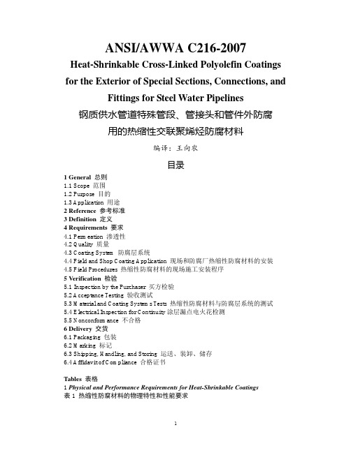
ANSI/AWWA C216-2007Heat-Shrinkable Cross-Linked Polyolefin Coatings for the Exterior of Special Sections, Connections, and Fittings for Steel Water Pipelines钢质供水管道特殊管段、管接头和管件外防腐用的热缩性交联聚烯烃防腐材料编译:王向农目录1 General 总则1.1 Scope 范围1.2 Purpose 目的1.3 Application 用途2 Reference参考标准3 Definition定义4 Requirements要求4.1 Permeation 渗透性4.2 Quality 质量4.3 Coating System 防腐层系统4.4 Field and Shop Coating Application 现场和防腐厂热缩性防腐材料的安装4.5 Field Procedures 热缩性防腐材料的现场施工安装程序5 Verification检验5.1 Inspection by the Purchaser 买方检验5.2 Acceptance Testing 验收测试5.3 Material and Coating Systems Tests 热缩性防腐材料与防腐层系统的测试5.4 Electrical Inspection for Continuity涂层漏点电火花检测5.5 Nonconformance 不合格6 Delivery交货6.1 Packaging 包装6.2 Marking 标记6.3 Shipping, Handling, and Storing 运送、装卸、储存6.4 Affidavit of Compliance 合格证书Tables表格1 Physical and Performance Requirements for Heat-Shrinkable Coatings表1 热缩性防腐材料的物理特性和性能要求SECTION 1: GENERAL第一章总则Sec. 1.1Scope范围This standard describes the material, application, and field-procedure requirements for protective exterior coatings consisting of heat-shrinkable, cross-linked polyolefin coatings. ANSI/AWWA C216 also describes the application of protective exterior coatings to special sections, connections, and fittings to be used in underground and underwater steel water pipelines.本标准叙述了采用热缩性交联聚烯烃材料的外防腐层的材料、用途和现场施工程序。
- 1、下载文档前请自行甄别文档内容的完整性,平台不提供额外的编辑、内容补充、找答案等附加服务。
- 2、"仅部分预览"的文档,不可在线预览部分如存在完整性等问题,可反馈申请退款(可完整预览的文档不适用该条件!)。
- 3、如文档侵犯您的权益,请联系客服反馈,我们会尽快为您处理(人工客服工作时间:9:00-18:30)。
07/2003AWT6134KPCS/CDMA 3.4V/28dBm Linear Power Amplifier ModulePRELIMINARY DATA SHEET - Rev 1.0Figure 1: Block DiagramV CC V REF RF IN RF OUT GNDV GNDV CC GND GND ruggedness. Selectable bias modes that optimize efficiency for different output power levels, and a shutdown mode with low leakage current, increase handset talk and standby time. The self-contained 4mm x 4mm surface mount package incorporates matching networks optimized for output power,efficiency, and linearity in a 50 Ω system.FEA TURES•InGaP HBT Technology •High Efficiency: 39%•Low Quiescent Current: 48 mA•Low Leakage Current in Shutdown Mode: <1 µA •V REF = +2.8 V (+2.7 V min over temp)•Optimized for a 50 Ω System•Low Profile Miniature Surface Mount Package:1.56mm Max•CDMA 1XRTT Compliant •CDMA 1xEV-DO CompliantAPPLICATIONS•Korean PCS CDMA Wireless HandsetsPRODUCT DESCRIPTIONThe AWT6134 meets the increasing demands for higher efficiency and linearity in CDMA 1XRTT handsets. The PA module is optimized for V REF = +2.8 V ,a requirement for compatibility with the Qualcomm 6000 chipset. The device is manufactured on an advanced InGaP HBT MMIC technology offering state-of-the-art reliability, temperature stability, and元器件交易网2PRELIMINARY DATA SHEET - Rev 1.007/2003AWT6134V CC RF OUT V REFRF IN V MODE GNDV CC GND GND GND Figure 2: Pinout (X-ray Top View)Table 1: Pin Description元器件交易网PRELIMINARY DATA SHEET - Rev 1.007/2003 AWT61343ELECTRICAL CHARACTERISTICSTable 2: Absolute Minimum and Maximum RatingsStresses in excess of the absolute ratings may cause permanentdamage. Functional operation is not implied under these conditions.Exposure to absolute ratings for extended periods of time mayadversely affect reliability.Table 3: Operating Rangesonly over the conditions defined in the electrical specifications.Notes:(1)For operation at T C = +85 °C and V CC = +3.2 V, P OUT is derated by 0.5 dB.元器件交易网4PRELIMINARY DATA SHEET - Rev 1.007/2003AWT6134Table 4: Electrical Specifications(T C = +25 °C, V CC = +3.4 V, V REF = +2.8 V, 50 Ω system)(1)ACPR and PAE limits apply to middle frequency only.元器件交易网PRELIMINARY DATA SHEET - Rev 1.007/2003AWT61345Table 5: Electrical Specifications(T C = +25 °C, V CC = +3.4 V, V REF = +2.9 V, V MODE = +2.9 V, 50 Ω system)Notes:(1)ACPR and PAE limits apply to middle frequency only.元器件交易网6PRELIMINARY DATA SHEET - Rev 1.007/2003AWT6134APPLICATION INFORMATIONTo ensure proper performance, refer to all relatedApplication Notes on the ANADIGICS web site:Shutdown ModeThe power amplifier may be placed in a shutdown mode by applying logic low levels (see Operating Ranges table) to both the V REF and V MODE voltages.Table 6: Bias ControlBias ModesThe power amplifier may be placed in either a Low Bias mode or a High Bias mode by applying the appropriate logic level (see Operating Ranges table)to the V MODE voltage. The Bias Control table lists the recommended modes of operation for various applications.RF INRF OUTFigure 3: Application Circuit Schematic元器件交易网PRELIMINARY DATA SHEET - Rev 1.007/2003AWT61347Figure 4: M7 Package Outline - 10 Pin 4mm x 4mm Surface Mount ModuleBBBAWT6134AWT6134LASER MARKEDFigure 5: Branding Specification元器件交易网8PRELIMINARY DATA SHEET - Rev 1.007/2003AWT6134COMPONENT PACKAGINGFigure 6: Tape & Reel PackagingTable 7: Tape & Reel Dimensions元器件交易网PRELIMINARY DATA SHEET - Rev 1.007/2003 AWT61349NOTES元器件交易网元器件交易网AWT6134NOTES10PRELIMINARY DATA SHEET - Rev 1.007/2003元器件交易网AWT6134 NOTESWARNINGANADIGICS products are not intended for use in life support appliances, devices or systems. Use of an ANADIGICS product in any such application without written consent is prohibited.IMPORTANT NOTICEANADIGICS, Inc.141 Mount Bethel RoadWarren, New Jersey 07059, U.S.A.Tel: +1 (908) 668-5000Fax: +1 (908) 668-5132URL: E-mail: Mktg@ANADIGICS, Inc. reserves the right to make changes to its products or to discontinue any product at any time without notice. The product specifications contained in Advanced Product Information sheets and Preliminary Data Sheets are subject to change prior to a product’s formal introduction. Information in Data Sheets have been carefully checked and are assumed to be reliable; however, ANADIGICS assumes no responsibilities for inaccuracies. ANADIGICS strongly urges customers to verify that the information they are using is current before placing orders.AWT6134ORDERING INFORMATION元器件交易网。