DTD133HS中文资料
DTD133HK中文资料

TransistorsRev.A 1/2Digital transistors (Includes resistors)DTD133HK / DTD133HSz Features1) A built-in bias resistor allows invertercircuit configuration without external resistors for input (see equivalent circuit diagram).2) The bias resistor consists of a thin-film resistor which is completely isolated, providing the capabilityto negative-bias the input, and avoiding parasitic effects.3) Operation starts by simply setting On/Off conditions, simplifying the design of equipment using the transistors.4) High packing density .z External dimensions (Unit : mm)z Absolute maximum ratings (T a=25°C)ParameterDTD133HK DTD133HS Unit V V mA mW °C °CSupply voltage Input voltage Output currentPowerdissipation Junction temperature Storage temperatureLimits 50500200300150−55 to +150−6 to +20Symbol V CC V I I CPd Tj Tstgz Package, marking, and packaging specificationsPart No.DTD133HK SMT3G08T1463000DTD133HSSPT −TP 5000Package MarkingPackaging codeBasic ordering unit (pieces)TransistorsRev.A 2/2z Electrical characteristics (T a=25°C)ParameterSymbol Min.Typ.Max.Unit Conditions−−−−56−2.31−0.1−−−2003.30.50.32.40.5−−4.29V V V mA µA −MHzk ΩV CC =5V , I O =100µA 2.0−−V O =0.3V , I O =20mA I O =50mA , I I =2.5mA V I =5VVCC =50V , V I =0V I O =50mA , V O =5VV CE =10V , I E = −50mA , f =100MHz∗−2.43.0 3.7−−Input voltage Output voltage Input current Output current DC current gain Transition frequencyInput resistance ∗Transition frequency of the device.Resistance ratioV I(off)V O(on)I I I O(off)G I f TR 1V I(on)R 2/R 1z Electrical characteristics curvesI N P U TV O L T A G E : V I (o n ) (V )OUTPUT CURRENT : I O (A)Fig.1 Input voltage vs. output current(ON characteristics)INPUT VOLTAGE : V I (off) (V)O U T P U T C U R R E N T : I o (A )500200100502010512Fig.2 Output current vs. input voltage(OFF characteristics)OUTPUT CURRENT : I O (A)D C C U R RE N T G A I N : G IFig.3 DC current gain vs. output currentcharacteristicsOUTPUT CURRENT : I O (A)O U T P U T V O L T A G E : V O (o n ) (V )Fig.4 Output voltage vs. output currentcharacteristicsAppendixAbout Export Control Order in JapanProducts described herein are the objects of controlled goods in Annex 1 (Item 16) of Export Trade ControlOrder in Japan.In case of export from Japan, please confirm if it applies to "objective" criteria or an "informed" (by MITI clause)on the basis of "catch all controls for Non-Proliferation of Weapons of Mass Destruction.Appendix1-Rev1.0。
DTDH技术文件(原理等)资料

一、电梯能量回馈装置的工作原理:电梯回馈装置是把电梯在不平衡载荷情况下曳引机所产生的电能经过逆变,变成为与电网同频、同相优质交流电并回馈到局域电网的设备。
供电梯主板、井道及轿厢照明、轿厢风扇等附近有负载的地方(或其它电梯及附属设备)使用。
电梯结构示意图由上示意图或知,电梯由曳引机拖动负载上下运行,而曳引机拖动的负载由轿厢和对重平衡块组成,只有当轿厢载重量约为50%(1吨载客电梯乘客为7人左右)时,轿厢和对重平衡块才相互平衡,否则轿厢和对重就会产生质量差。
电梯运行过程就是电能与机械能转换的过程,当电梯电梯重载上行或轻载下行时,需要给电梯提供能量使机械势能增加,电梯通过曳引机将电能转换为机械势能,曳引机处于耗电状态;当电梯轻载上行或重载下行时,运行过程需要使机械势能减少,电梯机械势能通过曳引机转换为电能,曳引机处于发电状态。
另外电梯在从高速运行到制动停止的过程,是机械动能消耗的过程,其中一部分动能则通过曳引机转换为电能,曳引机也处于发电过程。
曳引机发电过程产生的电能需要及时处理,不然对曳引机有严重的危害。
对于变频电梯,曳引机发电过程产生的电能通过变频器的三相逆变桥反向回到变频器的直流端,存储到储能电容里,而电容的容量有限,当曳引机产生的电能足够大,超过电容的容量,将造成电容损坏,所以多出的电能部分必须消耗掉。
常规的变频电梯处理此部分电能的方法是在电容端加装制动单元和制动电阻,当电容两端的电压到达一定值,制动单元动作,多余的电能通过制动电阻转换为热能散发到空中。
电能回馈装置替代制动单元和制动电阻,通过自动检测变频器的直流母线电压,将变频器的直流环节的直流电逆变成与交流电网同频同相的交流电,经多重噪声滤波环节后连接到交流电网,达到绿色、环保、节能的目的。
二、主要功能:PROPECT-DTDH电梯电能回馈装置是把电梯在不平衡载荷情况下曳引机所产生的电能经过逆变,变成为与电网同频、同相优质交流电返回到局域电网。
DTD123YKT146;中文规格书,Datasheet资料
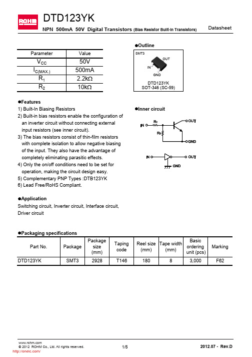
DatasheetDTD123YKNPN 500mA 50V Digital Transistors (Bias Resistor Built-in Transistors)l Features1) Built-In Biasing Resistorsl Inner circuit2) Built-in bias resistors enable the configuration of an inverter circuit without connecting external input resistors (see inner circuit).3) The bias resistors consist of thin-film resistors with complete isolation to allow negative biasing of the input. They also have the advantage of completely eliminating parasitic effects.4) Only the on/off conditions need to be set for operation, making the circuit design easy.5) Complementary PNP Types :DTB123YK 6) Lead Free/RoHS Compliant.l ApplicationSwitching circuit, Inverter circuit, Interface circuit, Driver circuitOUTINGNDDTD123YKSOT-346 (SC-59)*2 Each terminal mounted on a reference footprintFig.1 Input voltage vs. output current (ON characteristics) I N P U T V O L T A G E : V I (o n ) [V ]OUTPUT CURRENT : I O [mA] Fig.2 Output current vs. input voltage (OFF characteristics)O U T P U T C U R R E N T : I O [A ]INPUT VOLTAGE : V I(off)[V]O U T P U T C U R R E N T : I O [m A ]OUTPUT VOLTAGE : V O [V] Fig.4 DC current gain vs. output currentD C C U R RE N T G A I N : G IOUTPUT CURRENT : I O [mA]0100200300400500510Fig.5 Output voltage vs. output currentO U T P U T V O L T A G E : V O (o n ) [V ]OUTPUT CURRENT : I O[mA]l Dimensions (Unit : mm)Dimension in mm/inchesSMT3Patterm of terminal position areasNoticeN o t e sNo copying or reprod uction of this d ocument, in part or in whole, is permitted without theconsent of ROHM Co.,Ltd.The content specified herein is subject to change for improvement without notice.The content specified herein is for the purpose of introd ucing ROHM's prod ucts (hereinafter"Products"). If you wish to use any such Product, please be sure to refer to the specifications,which can be obtained from ROHM upon request.Examples of application circuits, circuit constants and any other information contained hereinillustrate the standard usage and operations of the Products. The peripheral conditions mustbe taken into account when designing circuits for mass production.Great care was taken in ensuring the accuracy of the information specified in this document.However, should you incur any d amage arising from any inaccuracy or misprint of suchinformation, ROHM shall bear no responsibility for such damage.The technical information specified herein is intended only to show the typical functions of andexamples of application circuits for the Prod ucts. ROHM d oes not grant you, explicitly orimplicitly, any license to use or exercise intellectual property or other rights held by ROHM andother parties. ROHM shall bear no responsibility whatsoever for any dispute arising from theuse of such technical information.The Products specified in this document are intended to be used with general-use electronicequipment or devices (such as audio visual equipment, office-automation equipment, commu-nication devices, electronic appliances and amusement devices).The Products specified in this document are not designed to be radiation tolerant.While ROHM always makes efforts to enhance the quality and reliability of its Prod ucts, aProduct may fail or malfunction for a variety of reasons.Please be sure to implement in your equipment using the Products safety measures to guardagainst the possibility of physical injury, fire or any other damage caused in the event of thefailure of any Product, such as derating, redundancy, fire control and fail-safe designs. ROHMshall bear no responsibility whatsoever for your use of any Product outside of the prescribedscope or not in accordance with the instruction manual.The Products are not designed or manufactured to be used with any equipment, device orsystem which requires an extremely high level of reliability the failure or malfunction of whichmay result in a direct threat to human life or create a risk of human injury (such as a medicalinstrument, transportation equipment, aerospace machinery, nuclear-reactor controller, fuel-controller or other safety device). ROHM shall bear no responsibility in any way for use of anyof the Prod ucts for the above special purposes. If a Prod uct is intend ed to be used for anysuch special purpose, please contact a ROHM sales representative before purchasing.If you intend to export or ship overseas any Product or technology specified herein that maybe controlled under the Foreign Exchange and the Foreign Trade Law, you will be required toobtain a license or permit under the Law.Thank you for your accessing to ROHM product informations.More detail product informations and catalogs are available, please contact us.ROHM Customer Support System/contact/分销商库存信息: ROHMDTD123YKT146。
强制性产品HS对照表

其他开关(低压电器)
00
电压≤1000伏的其他开关
18
其他装置(低压电器)
00
电压≤1000伏其他电路保护装置(用于电压不超过1000伏的线路)
19
低压成套开关设备
90
其他电力控制或分配的装置(电压不超过1000伏的线路)
20
小功率电动机
00
>750W ≤75KW多相交流电动机(输出功率不超过750瓦,但不超过75千瓦)
00
电弧(包括等离子弧)焊接机器人
40
TIG弧焊机
00
其他电弧(包括等离子弧)焊接机及装置(全自动或半自动的)
00
其他电弧(等离子弧)焊接机器及装置(非全自动或半自动)
00
螺旋焊管机[电弧(包括等离子弧)焊接式,全自动或半自动的]
90
其他焊接机器及装置
00
电气等焊接机器及装置零件(包括激光,其他光、光子束、超声波、电子束磁脉冲等)
00
干衣量≤10公斤的离心干衣机
00
脱水机
57
电热水器
00
储存式电热水器
00
即热式电热水器
00
其他电热水器
58
室内加热器
00
电气空间加热器
00
辐射式空间加热器
强制性产品HS对照表
附件
强制性产品认证目录产品与2014年HS编码对应表
序号
强制性产品认证目录产品名称
2014年商品编码
(HS编码)
商品编码对应的商品名称及备注
1
电线组件
00
其他电压≤1000伏电路连接器等电气装置
00
80V<额定电压≤1000V有接头电缆
欧洲电器大型电磁铁产品说明书

Dimensions: [mm]Scale - 1:17443640470744364047074436404707443640470T e m p e r a t u r eT pT L7443640470Further informationComponent Libraries:Altium_WE-HCF (23a)Downloads_CADENCE_WE-HCF (23a)Download_CadStar_WE-HCF (20a)Eagle_WE-HCF (23a)Download_IGS_WE-HCF_2818PSpice_WE-HCF (22a)Download_STP_WE-HCF-2818Spectre_WE-HCF (23a)Free Sample Order:Order free samples of this article directly here!Tutorials:■Single Coil Inductors (PDF)■Redefining Rated Current Measurements for Power Inductors (PDF)REDEXPERT:Calculate losses for 7443640470 in REDEXPERTWürth Elektronik eiSos GmbH & Co. KGEMC & Inductive SolutionsMax-Eyth-Str. 174638 WaldenburgGermanyCHECKED REVISION DATE (YYYY-MM-DD)GENERAL TOLERANCE PROJECTIONMETHODALa005.0012023-11-30DIN ISO 2768-1mDESCRIPTIONWE-HCF SMT High CurrentInductor ORDER CODE7443640470SIZE/TYPE BUSINESS UNIT STATUS PAGECautions and Warnings:The following conditions apply to all goods within the product series of WE-HCF of Würth Elektronik eiSos GmbH & Co. KG:General:•This electronic component was designed and manufactured for use in general electronic equipment.•Würth Elektronik must be asked for written approval (following the PPAP procedure) before incorporating the components into any equipment in fields such as military, aerospace, aviation, nuclear control, submarine, transportation (automotive control, train control, ship control), transportation signal, disaster prevention, medical, public information network, etc. where higher safety and reliability are especially required and/or if there is the possibility of direct damage or human injury.•Electronic components that will be used in safety-critical or high-reliability applications, should be pre-evaluated by the customer. •The component was designed and manufactured to be used within the datasheet specified values. If the usage and operation conditions specified in the datasheet are not met, the wire insulation may be damaged or dissolved.•Do not drop or impact the components, as the core may flake apart.•Würth Elektronik products are qualified according to international standards, which are listed in each product reliability report. Würth Elektronik does not guarantee any customer qualified product characteristics beyond Würth Elektroniks’ specifications, for its validity and sustainability over time.•The customer is responsible for the functionality of their own products. All technical specifications for standard products also apply to customer specific products.Product specific:Soldering:•The solder profile must comply with the Würth Elektronik technical soldering specification. All other profiles will void the warranty. •All other soldering methods are at the customers’ own risk.Cleaning and Washing:•Washing agents used during the production to clean the customer application may damage or change the characteristics of the wire insulation, marking or plating. Washing agents may have a negative effect on the long-term functionality of the product. Potting:•If the product is potted in the costumer application, the potting material may shrink or expand during and after hardening. Shrinking could lead to an incomplete seal, allowing contaminants into the core. Expansion could damage the core or wire contacts. Werecommend a manual inspection after potting to avoid these effects. Storage Conditions:• A storage of Würth Elektronik products for longer than 12 months is not recommended. Within other effects, the terminals may suffer degradation, resulting in bad solderability. Therefore, all products shall be used within the period of 12 months based on the day of shipment.•Do not expose the components to direct sunlight.•The storage conditions in the original packaging are defined according to DIN EN 61760-2.Packaging:•The packaging specifications apply only to purchase orders comprising whole packaging units. If the ordered quantity exceeds or is lower than the specified packaging unit, packaging in accordance with the packaging specifications cannot be ensured. Handling:•Violation of the technical product specifications such as exceeding the nominal rated current will void the warranty•Applying currents with audio-frequency signals may result in audible noise due to the magnetostrictive material properties. •Due to heavy weight of the components, strong forces and high accelerations may have the effect to damage the electrical connection or to harm the circuit board and will void the warranty.These cautions and warnings comply with the state of the scientific and technical knowledge and are believed to be accurate and reliable.However, no responsibility is assumed for inaccuracies or incompletenessWürth Elektronik eiSos GmbH & Co. KGEMC & Inductive SolutionsMax-Eyth-Str. 174638 WaldenburgGermanyCHECKED REVISION DATE (YYYY-MM-DD)GENERAL TOLERANCE PROJECTIONMETHODALa005.0012023-11-30DIN ISO 2768-1mDESCRIPTIONWE-HCF SMT High CurrentInductor ORDER CODE7443640470SIZE/TYPE BUSINESS UNIT STATUS PAGEImportant NotesThe following conditions apply to all goods within the product range of Würth Elektronik eiSos GmbH & Co. KG:1. General Customer ResponsibilitySome goods within the product range of Würth Elektronik eiSos GmbH & Co. KG contain statements regarding general suitability for certain application areas. These statements about suitability are based on our knowledge and experience of typical requirements concerning the areas, serve as general guidance and cannot be estimated as binding statements about the suitability for a customer application. The responsibility for the applicability and use in a particular customer design is always solely within the authority of the customer. Due to this fact it is up to the customer to evaluate, where appropriate to investigate and decide whether the device with the specific product characteristics described in the product specification is valid and suitable for the respective customer application or not.2. Customer Responsibility related to Specific, in particular Safety-Relevant ApplicationsIt has to be clearly pointed out that the possibility of a malfunction of electronic components or failure before the end of the usual lifetime cannot be completely eliminated in the current state of the art, even if the products are operated within the range of the specifications.In certain customer applications requiring a very high level of safety and especially in customer applications in which the malfunction or failure of an electronic component could endanger human life or health it must be ensured by most advanced technological aid of suitable design of the customer application that no injury or damage is caused to third parties in the event of malfunction or failure of an electronic component. Therefore, customer is cautioned to verify that data sheets are current before placing orders. The current data sheets can be downloaded at .3. Best Care and AttentionAny product-specific notes, cautions and warnings must be strictly observed. Any disregard will result in the loss of warranty.4. Customer Support for Product SpecificationsSome products within the product range may contain substances which are subject to restrictions in certain jurisdictions in order to serve specific technical requirements. Necessary information is available on request. In this case the field sales engineer or the internal sales person in charge should be contacted who will be happy to support in this matter.5. Product R&DDue to constant product improvement product specifications may change from time to time. As a standard reporting procedure of the Product Change Notification (PCN) according to the JEDEC-Standard inform about minor and major changes. In case of further queries regarding the PCN, the field sales engineer or the internal sales person in charge should be contacted. The basic responsibility of the customer as per Section 1 and 2 remains unaffected.6. Product Life CycleDue to technical progress and economical evaluation we also reserve the right to discontinue production and delivery of products. As a standard reporting procedure of the Product Termination Notification (PTN) according to the JEDEC-Standard we will inform at an early stage about inevitable product discontinuance. According to this we cannot guarantee that all products within our product range will always be available. Therefore it needs to be verified with the field sales engineer or the internal sales person in charge about the current product availability expectancy before or when the product for application design-in disposal is considered. The approach named above does not apply in the case of individual agreements deviating from the foregoing for customer-specific products.7. Property RightsAll the rights for contractual products produced by Würth Elektronik eiSos GmbH & Co. KG on the basis of ideas, development contracts as well as models or templates that are subject to copyright, patent or commercial protection supplied to the customer will remain with Würth Elektronik eiSos GmbH & Co. KG. Würth Elektronik eiSos GmbH & Co. KG does not warrant or represent that any license, either expressed or implied, is granted under any patent right, copyright, mask work right, or other intellectual property right relating to any combination, application, or process in which Würth Elektronik eiSos GmbH & Co. KG components or services are used.8. General Terms and ConditionsUnless otherwise agreed in individual contracts, all orders are subject to the current version of the “General Terms and Conditions of Würth Elektronik eiSos Group”, last version available at .Würth Elektronik eiSos GmbH & Co. KGEMC & Inductive SolutionsMax-Eyth-Str. 174638 WaldenburgGermanyCHECKED REVISION DATE (YYYY-MM-DD)GENERAL TOLERANCE PROJECTIONMETHODALa005.0012023-11-30DIN ISO 2768-1mDESCRIPTIONWE-HCF SMT High CurrentInductor ORDER CODE7443640470SIZE/TYPE BUSINESS UNIT STATUS PAGE。
步进电机说明书

!"#
配套驱动器型号: SH-2H057M 驱动器细分数:5, 360 0.33 Nm 0.60Nm 0.62Nm 480 0.20 Nm 0.51Nm 0.52Nm 步距角:0.36° 600 0.16 Nm 0.36Nm 0.38Nm 0.33Nm 0.32Nm 720
驱 动 器 电 流 为 额 定 电流 , 120 0.64Nm 0.72Nm 0.89Nm 240 0.61 Nm 0.67Nm 0.80Nm
!"#$%& '
!"#
电机型号 L Φd 电机轴 23HS2001 53 23HS2003 53 Φ6.35
0 -0.013
A 红线
23HS3002 75 23HS3002Z 75 Φ8.0
0 -0.013
A 绿线
电机轴铣扁,厚度0.5mm
B 黄线
B 蓝线
!"#
测试电机型号: 23HS2001、23HS2003、23HS3002 、23HS3002Z 测试条件 转速 (转/分) 23HS2001(DC24V) 转矩 23HS2003(DC40V) 23HS3002(DC40V) 23HS3002Z(DC40V) 驱动器电压:DC24V、DC40V, 30 0.72Nm 0.72Nm 1.02Nm 60 0.70Nm 0.73Nm 0.96Nm
Start MicroStep Co., Ltd.
!"#$%&'()*+
3
! " # $ SERIES STEP MOTORS
57BYG096
!" -25 - +55 !" !" 500V DC 100M 0.1 0.3mm 0.02mm Max 85 Max B ! "10-85% ! !"#$"% Min ! "
MS31xxx中文资料
MS31xxx中⽂资料Shell Size/No. of Dimensions in InchesInsert Arrange-Contacts/Digi-Key Price EachL L1N Q U V Fitting XY Amphenol ment No.Size DescriptionPart No.11050Max.Max.Ref.Max.Ref.ThreadRef.Ref.Part No.Straight Plugs with Solid Shells10SL-33/16Straight Plug w/Socket 97-3106A-10SL-3S-ND 12.008.40 6.2497-3106A-10SL-3S 10SL-42/16Straight Plugw/Socket 97-3106A-10SL-4S-ND 11.357.95 5.911-3/8—3/47/8—5/8-24——97-3106A-10SL-4S 12S-32/16Straight Plugw/Pins 97-3106A-12S-3P-ND 10.407.28 5.411-7/16—25/321—5/8-24——97-3106A-12S-3P Straight Plug w/Socket 97-3106A-12S-3S-ND 11.137.79 5.7997-3106A-12S-3S 14S-13/16Straight Plug w/Pins 97-3106A-14S-1P-ND 10.437.30 5.4397-3106A-14S-1P Straight Plug w/Socket 97-3106A-14S-1S-ND 12.308.61 6.4097-3106A-14S-1S 14S-24/16Straight Plug w/Pins 97-3106A-14S-2P-ND 10.387.27 5.401-15/32—7/81-1/8—3/4-20——97-3106A-14S-2P Straight Plug w/Socket9.026.7097-3106A-14S-2S SS RRL MKMS3100A Wall Mount ReceptacleMounting Holes .147 Dia. sizes 24,28.120 Dia.all other sizesCInsert Patterns (Front face of pin insert shown.Drawings not to scale.)SERVICE RATING:INST A D EB C Limited Operating DC 2507001250175024504200Voltages at Sea Level AC(rms)200500900125017503000TEST CURRENT: Contact Size 16 = 13 amperes, Contact Size 12 = 23 amperes NOTE: Transients were not considered in calculating these values.NOTE: Limiting operating voltage at 50,000 feet altitude are approx. 25% of the sea level values.Insert Arrangement Service Rating10SL-3A18-10A 18-11A18-12A18-16C18-19A20-4D20-29A22-14A 22-19A24-7A28-11A28-16A28-21A22-2224-1114S-716-1016-1118-1124-28INST.20-15A20-16A20-27A 20-7A,B,H,G = D C,D,E,F = A10SL-4A 12S-3A 14S-1A14S-2INST.14S-5INST.14S-6INST.18-4D18-8A18-1B,C,F,G = A all others = INST.A C BA BB AA C BD A C BE B D CA E ADCBF A EF G DCBA E D CBCB AD EFG H I J CBA D CB A D EF GH D A C BD EA CBE DB A D E F GHK JBCA D ABCDEFGHBCAD EFGA BCD EF GH I AB C D E FGHIJ K L M N A BC D EHJLK M P N TSRAB C D E F GH JLK MN P A B CD EF G HJ L KMNPO I AB C DEFG HJ LK M N U TV PSR A B C D E F G H JT Y V Q P S X R W A B C DEF G H JL K M N U W XTV IP S R ABC DEF GHJ L K M N U T V Q PS R A B C Dn p r sE F G H Jgh i k m L K M N V U W X Z R P b a c d fe T S LNAVNL N Q V MS3106A Straight Plug (97 Series)MS3108B Angle Plug (97 Series) XL 1UVQSizes 10SL, 14SVL1Q YShell is split longi-tudinally for conve-nient solder or in-spection. Frontshell is keyed to allow the 90 degree angle housing to be rotated and locked at any 45 degree increment. Underwriters Laboratories approved recognition File E115497. Canadian Standard Association Certification File LR69183 L 1MK N 1ASS R RSS R R16128Panel OpeningOCoupling ring ma-chined from solid alu-minum bar stock forhigh tensile strength.Mates with all types of 97 series receptacles.Front shell includespolarization keyway.Solid shell. Threadedbackshell.Mounting Holes.147 Dia. sizes 24,28.120 Dia. all other sizes97 Series Plugs(Continued)LKN XLKNML KZL M NBAAB CD A C IG DFEHB CA BA BC A BA BCDES SShell Size/No. of Dimensions in InchesInsert Arrange-Contacts/Digi-KeyPrice EachLL1N Q U V Fitting XY Amphenol ment No.Size Description Part No.11050Max.Max.Ref.Max.Ref.ThreadPart No.14S-55/16Straight Plug w/Pins 97-3106A-14S-5P-ND 11.608.12 6.0497-3106A-14S-5P Straight Plug w/Socket 97-3106A-14S-5S-ND 13.839.687.1997-3106A-14S-5S 14S-66/16Straight Plug w/Pins 97-3106A-14S-6P-ND 12.038.42 6.261-15/32—7/81-1/8—3/4-20——97-3106A-14S-6P Straight Plug w/Socket 97-3106A-14S-6S-ND 13.959.777.2697-3106A-14S-6S 16S-17/16Straight Plug w/Pins 97-3106A-16S-1P-ND 12.038.42 6.2697-3106A-16S-1P Straight Plug w/Socket 97-3106A-16S-1S-ND 15.4010.788.0197-3106A-16S-1S 16S-85/16Straight Plug w/Pins 97-3106A-16S-8P-ND 13.439.40 6.991-15/32—11-1/4—7/8-20——97-3106A-16S-8P Straight Plug w/Socket 97-3106A-16S-8S-ND 13.939.757.2597-3106A-16S-8S 18-110/16Straight Plug w/Pins 97-3106A-18-1P-ND 15.7811.058.2197-3106A-18-1P Straight Plug w/Socket 97-3106A-18-1S-ND 17.4512.229.0897-3106A-18-1S 18-44/16Straight Plug w/Pins 97-3106A-18-4P-ND 14.6010.227.6097-3106A-18-4P Straight Plug w/Socket 97-3106A-18-4S-ND 15.7511.038.1997-3106A-18-4S 18-84/1#12,Straight Plug w/Pins 97-3106A-18-8P-ND 17.2411.269.4497-3106A-18-8P 4/7#16Straight Plug w/Socket 97-3106A-18-8S-ND 18.6212.1610.2097-3106A-18-8S 18-104/12Straight Plug w/Pins 97-3106A-18-10P-ND 17.4812.249.0997-3106A-18-10P Straight Plug w/Socket 97-3106A-18-10S-ND 18.6212.1610.2097-3106A-18-10S 18-115/12Straight Plug w/Pins 97-3106A-18-11P-ND 17.4812.249.091-31/32—1-1/81-20——97-3106A-18-11P Straight Plug w/Socket 97-3106A-18-11S-ND 17.2411.269.4497-3106A-18-11S 18-126/16Straight Plug w/Pins 97-3106A-18-12P-ND 14.3310.037.4597-3106A-18-12P Straight Plug w/Socket 97-3106A-18-12S-ND 17.4812.249.0997-3106A-18-12S 18-161/12Straight Plug w/Pins 97-3106A-18-16P-ND 17.4812.249.0997-3106A-18-16P Straight Plug w/Socket 97-3106A-18-16S-ND 19.6412.8210.7697-3106A-18-16S 18-1910/16Straight Plug w/Pins 97-3106A-18-19P-ND 22.5214.4212.7797-3106A-18-19P Straight Plug w/Socket 97-3106A-18-19S-ND 19.2112.5410.5297-3106A-18-19S 20-44/12Straight Plug w/Pins 97-3106A-20-4P-ND 20.1613.1611.0497-3106A-20-4P Straight Plug w/Socket 97-3106A-20-4S-ND 26.3516.8714.9497-3106A-20-4S 20-78/16Straight Plug w/Pins 97-3106A-20-7P-ND 20.1613.1611.0497-3106A-20-7P Straight Plug w/Socket 97-3106A-20-7S-ND 21.6614.1411.8697-3106A-20-7S 20-157/12Straight Plug w/Pins 97-3106A-20-15P-ND 22.0914.4212.0997-3106A-20-15P Straight Plug w/Socket 97-3106A-20-15S-ND 27.7017.7315.701-7/8—1-1/41-15/32—1-3/16-18——97-3106A-20-15S 20-169/2#12,Straight Plug w/Pins 97-3106A-20-16P-ND 22.1114.4412.1197-3106A-20-16P 9/7#16Straight Plug w/Socket 97-3106A-20-16S-ND 22.5014.4012.7597-3106A-20-16S 20-2714/16Straight Plug w/Pins 97-3106A-20-27P-ND 19.7812.9210.8397-3106A-20-27P Straight Plug w/Socket 97-3106A-20-27S-ND 23.1814.8413.1497-3106A-20-27S 20-2917/16Straight Plug w/Pins 97-3106A-20-29P-ND 21.0713.7511.5497-3106A-20-29P Straight Plug w/Socket 97-3106A-20-29S-ND 25.4516.2914.4397-3106A-20-29S 22-1419/16Straight Plug w/Pins 97-3106A-22-14P-ND 24.0515.4013.6397-3106A-22-14P Straight Plug w/Socket 97-3106A-22-14S-ND 27.3217.4915.4897-3106A-22-14S 22-1914/16Straight Plug w/Pins 97-3106A-22-19P-ND 23.5815.1013.371-31/32—1-3/81-19/32—1-3/16-18——97-3106A-22-19P Straight Plug w/Socket97-3106A-22-19S-ND 24.0515.4013.6397-3106A-22-19S 24-716/2 #12,Straight Plug w/Pins 97-3106A-24-7P-ND 28.4618.2216.1397-3106A-24-7P 16/14 #16Straight Plug w/Socket 97-3106A-24-7S-ND 30.8319.7317.4797-3106A-24-7S 24-2824/16Straight Plug w/Pins 97-3106A-24-28P-ND 29.7719.0616.872-1/4—1-1/21-23/32—1-7/16-18——97-3106A-24-28P Straight Plug w/Socket 97-3106A-24-28S-ND 33.7121.5819.1097-3106A-24-28S 28-1122/4#12,Straight Plug w/Pins97-3106A-28-11P-ND 32.2720.6518.2997-3106A-28-11P 22/18#16Straight Plug w/Socket 97-3106A-28-11S-ND 34.6624.2721.6797-3106A-28-11S 28-1620/16Straight Plug w/Pins 97-3106A-28-16P-ND 33.2321.2718.842-1/4—1-3/41-31/32—1-7/16-18——97-3106A-28-16P Straight Plug w/Socket 97-3106A-28-16S-ND 33.6621.5519.0897-3106A-28-16S 28-2137/16 Straight Plug w/Pins 97-3106A-28-21P-ND 34.5424.1821.5997-3106A-28-21P Straight Plug w/Socket97-3106A-28-21S-ND38.9427.2624.3497-3106A-28-21SAngle Plugs with Split Shell10SL-33/16Angle Plug w/Socket 97-3108B-10SL-3S-ND 16.0311.228.3497-3108B-10SL-3S 10SL-42/16Angle Plugw/Socket 97-3108B-10SL-4S-ND 15.3010.717.96—1-1/2—7/815/8-24——97-3108B-10SL-4S 14S-13/16Angle Plug w/Pins 97-3108B-14S-1P-ND 13.939.757.2597-3108B-14S-1P Angle Plug w/Socket 97-3108B-14S-1S-ND 14.2810.007.4397-3108B-14S-1S 14S-24/16Angle Plug w/Pins 97-3108B-14S-2P-ND 13.809.667.1897-3108B-14S-2P Angle Plug w/Socket 97-3108B-14S-2S-ND14.9010.437.75—1-23/32—1-1/81-1/163/4-2021/32—97-3108B-14S-2S 14S-55/16Angle Plug w/Pins 97-3108B-14S-5P-ND 15.1310.597.8797-3108B-14S-5P Angle Plug w/Socket 97-3108B-14S-5S-ND 15.5510.898.0997-3108B-14S-5S 14S-66/16Angle Plug w/Pins 97-3108B-14S-6P-ND 15.5510.898.0997-3108B-14S-6P Angle Plug w/Socket 97-3108B-14S-6S-ND 15.9811.198.3197-3108B-14S-6S 18-110/16Angle Plug w/Pins 97-3108B-18-1P-ND 22.0214.3712.0697-3108B-18-1P Angle Plug w/Socket 97-3108B-18-1S-ND 24.0815.4113.65—2-5/32—1-11/321-3/161-201-41/641-41/6497-3108B-18-1S 18-44/16Angle Plug w/Pins 97-3108B-18-4P-ND 18.5012.0810.1397-3108B-18-4P Angle Plug w/Socket97-3108B-18-4S-ND19.7412.8910.8197-3108B-18-4SA(Continued)Shell Size/Dimensions in InchesInsert No. ofB Min X Min Arrange-Contacts/Digi-KeyPrice EachFull N Cable Amphenol ment No.SizeDescription Part No.11050Thread K L M Dia.R S Dim.Z Part No.3/16Plug w/Socket MS3106E-10SL-3S-ND *14.7010.297.65—.531 2.129—.896—.946.281—MS3106E-10SL-30S 3/16 Plug w/Socket MS3106F-10SL-3S-ND?16.7011.698.69—.531 2.129—.896—.946.281—MS3106F-10SL-3S 10SL-33/16Plug w/Socket MS3106R-10SL-3S-ND?15.2510.687.93—.531 1.057 1.120.807—.946——MS3106R-10SL-3S3/16Recept. w/Pins MS3102E-10SL-3P-ND *7.24 4.11 3.03.391.672.297.562.625.719 1.000—.422MS3102E-10SL-3P 3/16Recept. w/Pins MS3102R-10SL-3P-ND? 6.47 3.67 2.71.391.672.297.562.625.719 1.000—.422MS3102R-10SL-3P 2/16Plug w/Socket MS3106A-10SL-4S-ND 15.0810.567.84—.531.937———.946——MS3106A-10SL-4S 2/16Plug w/Socket MS3106E-10SL-4S-ND *16.7811.758.73—.531 2.129—.896—.946.281—MS3106E-10SL-4S 10SL-42/16Plug w/Socket MS3106F-10SL-4S-ND?14.8810.427.74—.531 2.129—.896—.946.281—MS3106F-10SL-4S2/16Recept. w/Pins MS3102E-10SL-4P-ND * 6.60 3.75 2.76.391.672.297.562.625.719 1.000—.422MS3102E-10SL-4P 2/16Recept. w/Pins MS3102R-10SL-4P-ND? 5.86 3.33 2.45.391.672.297.562.625.719 1.000—.422MS3102R-10SL-4P 4/16Plug w/Pins MS3106F-14S-2P-ND?12.808.96 6.66—.531 2.201— 1.021— 1.123.406—MS3106F-14S-2P 4/16Plugw/Socket MS3106A-14S-2S-ND 11.708.19 6.09—.531.937——— 1.123——MS3106A-14S-2S 4/16Plug w/Socket MS3106F-14S-2S-ND?16.9111.049.26—.531 2.201— 1.021— 1.123.406—MS3106F-14S-2S 14S-24/16Recept. w/Pins MS3102E-14S-2P-ND *8.82 5.30 4.12.450.672.297.562.750.906 1.188—.422MS3102E-14S-2P4/16Recept. w/Socket MS3102E-14S-2S-ND *8.74 4.96 3.66.450.672.297.562.750.906 1.188—.422MS3102E-14S-2S4/16Recept. w/Pins MS3102R-14S-2P-ND? 5.93 3.37 2.48.450.672.297.562.750.906 1.188—.422MS3102R-14S-2P4/16Recept. w/Socket MS3102R-14S-2S-ND?8.84 5.02 3.70.450.672.297.562.750.906 1.188—.422MS3102R-14S-2S5/16Plug w/Pins MS3106A-14S-5P-ND 11.588.11 6.02—.531.937——— 1.123——MS3106A-14S-5P 5/16Plug w/Socket MS3106A-14S-5S-ND 13.009.10 6.76—.531.937——— 1.123——MS3106A-14S-5S 14S-55/16Recept. w/Pins MS3102E-14S-5P-ND *7.67 4.36 3.21.450.672.297.562.750.906 1.188—.422MS3102E-14S-5P5/16Recept. w/Pins MS3102R-14S-5P-ND?9.08 5.15 3.80.450.672.297.562.750.906 1.188—.422MS3102R-14S-5P6/16Plug w/Socket MS3106A-14S-6S-ND 13.009.10 6.76—.531.937——— 1.123——MS3106A-14S-6S 6/16Plug w/Socket MS3106F-14S-6S-ND?16.8011.768.74—.531 2.201— 1.021— 1.123.406—MS3106F-14S-6S 6/16Recept. w/Pins MS3102E-14S-6P-ND *7.84 4.45 3.28.450.672.297.562.750.906 1.188—.422MS3102E-14S-6P 14S-66/16Recept. w/Socket MS3102E-14S-6S-ND *9.84 5.91 4.60.450.672.297.562.750.906 1.188—.422MS3102E-14S-6S6/16Recept. w/Pins MS3102R-14S-6P-ND? 5.49 3.12 2.30.450.672.297.562.750.906 1.188—.422MS3102R-14S-6P 6/16 Recept. w/Socket MS3102R-14S-6S-ND?9.01 5.12 3.77.450.672.297.562.750.906 1.188—.422MS3102R-14S-6S 14S-73/16Plug w/Socket MS3106F-14S-7S-ND?17.0511.139.34—.531 2.201— 1.021— 1.123.406—MS3106F-14S-7S 7/16Plug w/Socket MS3106A-16S-1S-ND 15.4810.848.05—.531.937——— 1.250——MS3106A-16S-1S 7/16Plug w/Socket MS3106F-16S-1S-ND?23.1815.1312.69—.531 2.201— 1.151— 1.250.500—MS3106F-16S-1S 16S-17/16Recept. w/Pins MS3102E-16S-1P-ND *8.49 5.10 3.97.450.672.297.562.875.969 1.281—.422MS3102E-16S-1P7/16Recept. w/Pins MS3102R-16S-1P-ND? 6.80 3.86 2.85.450.672.297.562.875.969 1.281—.422MS3102R-16S-1P 3/12 Plug w/Socket MS3106A-16-10S-ND 16.5311.578.60—.719 1.124——— 1.250——MS3106A-16-10S 16-103/12Plugw/Socket MS3106F-16-10S-ND?23.0014.7213.04—.719 2.524— 1.151— 1.250.500—MS3106F-16-10S 16-112/12Recept. w/Pins MS3102R-16-11P-ND? 6.83 3.88 2.86.625.860.484.750.875.969 1.281—.672MS3102R-16-11P10/16Recept. w/Pins MS3102E-18-1P-ND *10.20 6.12 4.76.625.891.453.750 1.000 1.062 1.375—.641§MS3102E-18-1P 18-110/16Recept. w/Pins MS3102R-18-1P-ND?10.14 6.09 4.74.625.891.453.750 1.000 1.062 1.375—.641§MS3102R-18-1P10/16Plug w/Socket MS3106A-18-1S-ND 18.1211.839.92—.719 1.219——— 1.333——MS3106A-18-1S18-115/12Recept. w/Pins MS3102E-18-11P-ND *8.68 4.93 3.63.625.891.453.750 1.000 1.062 1.375—.641§MS3102E-18-11P 20-2714/16Recept. w/Pins MS3102R-20-27P-ND?10.80 6.48 5.04.625.891.453.750 1.125 1.156 1.500—.641§MS3102R-20-27P 22-1419/16Recept. w/Pins MS3102E-22-14P-ND *11.43 6.86 5.34.625.891.453.750 1.250 1.250 1.625—.641§MS3102E-22-14P 22-1914/16Recept. w/Socket MS3102E-22-19S-ND *12.008.40 6.24.625.891.453.750 1.250 1.250 1.625—.641§MS3102E-22-19S 22-224/8Recept. w/Pins MS3102E-22-22P-ND *14.9010.437.75.625.891.453.750 1.250 1.250 1.625—.641§MS3102E-22-22P 3/#8 6/#12Recept. w/Pins MS3102R-24-11P-ND?11.658.166.06.625.953.453.812 1.375 1.375 1.750—.578§MS3102R-24-11P 24-113/#8 6/#12Plug w/SocketMS3106R-24-11S-ND?23.8315.2513.51—.7191.2911.9941.557—1.715——MS3106R-24-11SShell Size/No. of Dimensions in InchesInsert Arrange-Contacts/Digi-Key Price EachL L1N Q U V Fitting XY Amphenol ment No.Size DescriptionPart No.11050Max.Max.Ref.Max.Ref.ThreadRef.Ref.Part No.18-84/1#12,Angle Plug w/Pins 97-3108B-18-8P-ND 22.0214.3712.0697-3108B-18-8P 4/7#16Angle Plug w/Socket 97-3108B-18-8S-ND 23.3915.2712.8197-3108B-18-8S 18-104/12Angle Plug w/Pins 97-3108B-18-10P-ND 21.3813.9511.7097-3108B-18-10P Angle Plug w/Socket 97-3108B-18-10S-ND 23.3915.2712.8197-3108B-18-10S 18-115/12Angle Plug w/Pins 97-3108B-18-11P-ND 21.3813.9511.7097-3108B-18-11P Angle Plug w/Socket 97-3108B-18-11S-ND 22.0214.3712.06—2-5/32—1-11/321-3/161-201-41/641-41/6497-3108B-18-11S 18-126/16Angle Plug w/Pins 97-3108B-18-12P-ND 20.2613.2311.0997-3108B-18-12P Angle Plug w/Socket 97-3108B-18-12S-ND 21.3813.9511.7097-3108B-18-12S 18-161/12Angle Plug w/Pins 97-3108B-18-16P-ND 22.0414.3912.0797-3108B-18-16P Angle Plug w/Socket 97-3108B-18-16S-ND 24.1015.4313.6697-3108B-18-16S 18-1910/16Angle Plug w/Pins 97-3108B-18-19P-ND 27.1417.3715.3897-3108B-18-19P Angle Plug w/Socket97-3108B-18-19S-ND22.7014.5312.8797-3108B-18-19SMSwAShell Size No. of Dimensions in InchesInsert Con-AV Arrange-tacts/Digi-Key Price Each Coupling K L L1M N N1O R S Fitting Amphenol ment No.Size DescriptionPart No.11050Thread Ref.Max.Max.Ref.Ref.Ref.Ref.Ref.Ref.ThreadPart No.Receptacles With Solid Shells10SL-33/16Cable recept. w/pins97-3101A-10SL-3P-ND 14.089.867.3297-3101A-10SL-3P Box mount recept. w/pins 97-3102A-10SL-3P-ND 9.69 5.82 4.53 5/8-245/641-9/3261.649/163/411/16.81223/3215/8-2497-3102A-10SL-3P 10SL-42/16Cable recept. w/pins97-3101A-10SL-4P-ND 13.439.40 6.9997-3101A-10SL-4P Box mount recept. w/pins 97-3102A-10SL-4P-ND 8.91 5.35 4.1697-3102A-10SL-4P 12S-32/16Box mount recept. w/pins 97-3102A-12S-3P-ND 8.27 4.70 3.4697-3102A-12S-3P Box mount recept. w/socket 97-3102A-12S-3S-ND 8.88 5.04 3.713/4-205/641-15/3231/329/1625/3211/16.81213/161-3/325/8-2497-3102A-12S-3S Wall mount recept. w/pins 97-3100A-14S-1P-ND 12.008.40 6.2497-3100A-14S-1P Wall mount recept.w/socket 97-3100A-14S-1S-ND 12.308.61 6.4097-3100A-14S-1S 14S-13/16Cable recept. w/pins 97-3101A-14S-1P-ND 14.7810.357.6997-3101A-14S-1P Cable recept. w/socket 97-3101A-14S-1S-ND 15.0010.507.8097-3101A-14S-1S Wall mount recept. w/pins 97-3100A-14S-2P-ND 13.359.35 6.9597-3100A-14S-2P Wall mount recept. w/socket 97-3100A-14S-2S-ND 12.588.81 6.5497-3100A-14S-2S 14S-24/16Cable recept. w/pins 97-3101A-14S-2P-ND 14.7010.297.6597-3101A-14S-2P Cable recept. w/socket 97-3101A-14S-2S-ND 15.5510.898.0997-3101A-14S-2S Wall mount recept. w/pins 97-3100A-14S-5P-ND 13.359.35 6.957/8-205/641-15/3261/649/167/83/4.93829/321-3/163/4-2097-3100A-14S-5P Wall mount recept. w/socket 97-3100A-14S-5S-ND 12.038.42 6.2697-3100A-14S-5S 14S-55/16Cable recept. w/pins 97-3101A-14S-5P-ND 15.8511.108.2597-3101A-14S-5P Cable recept. w/socket 97-3101A-14S-5S-ND 16.5511.598.6197-3101A-14S-5S Wall mount recept. w/pins 97-3100A-14S-6P-ND 12.038.42 6.2697-3100A-14S-6P Wall mount recept. w/socket 97-3100A-14S-6S-ND 13.839.687.1997-3100A-14S-6S 14S-66/16Cable recept. w/pins 97-3101A-14S-6P-ND 16.5511.598.6197-3101A-14S-6P Cable recept. w/socket 97-3101A-14S-6S-ND 16.9311.858.8197-3101A-14S-6S Box mount recept. w/pins 97-3102A-16S-1P-ND 11.677.01 5.4597-3102A-16S-1P 16S-17/16Box mount recept. w/socket 97-3102A-16S-1S-ND 11.887.13 5.5597-3102A-16S-1S Box mount recept. w/pins 97-3102A-16S-8P-ND 11.52 6.92 5.381-205/641-15/3261/649/1617/8 1.06231/321-9/327/8-2097-3102A-16S-8P 16S-85/16Box mount recept. w/socket 97-3102A-16S-8S-ND 11.977.19 5.5997-3102A-16S-8S Box mount recept. w/pins 97-3102A-18-1P-ND 13.259.28 6.8997-3102A-18-1P 18-110/16Box mount recept. w/socket 97-3102A-18-1S-ND 12.788.95 6.6597-3102A-18-1S Box mount recept. w/pins 97-3102A-18-4P-ND 11.52 6.92 5.3897-3102A-18-4P 18-44/16Box mount recept. w/socket 97-3102A-18-4S-ND 10.407.28 5.4197-3102A-18-4S 4/1#12,Box mount recept. w/pins 97-3102A-18-8P-ND 13.259.28 6.8997-3102A-18-8P 18-84/7#16Box mount recept. w/socket 97-3102A-18-8S-ND14.4810.147.5397-3102A-18-8S Box mount recept. w/pins 97-3102A-18-10P-ND 12.308.61 6.4097-3102A-18-10P 18-104/12Box mount recept. w/socket 97-3102A-18-10S-ND 14.4810.147.531-1/8-181/81-63/641-3/83/41-1/81 1.1881-1/161-3/81-2097-3102A-18-10S Box mount recept. w/pins 97-3102A-18-11P-ND 12.308.61 6.4097-3102A-18-11P 18-115/12Box mount recept. w/socket 97-3102A-18-11S-ND 11.538.07 6.0097-3102A-18-11S Box mount recept. w/pins 97-3102A-18-12P-ND 11.207.84 5.8397-3102A-18-12P 18-126/16Box mount recept. w/socket 97-3102A-18-12S-ND 10.707.49 5.5797-3102A-18-12S Box mount recept. w/pins 97-3102A-18-16P-ND 11.738.21 6.1097-3102A-18-16P 18-161/12Box mount recept. w/socket 97-3102A-18-16S-ND 15.0010.507.8097-3102A-18-16S Box mount recept. w/pins 97-3102A-18-19P-ND19.0712.4510.4497-3102A-18-19P 18-1910/16Box mount recept. w/socket 97-3102A-18-19S-ND 13.059.14 6.7997-3102A-18-19S Box mount recept. w/pins 97-3102A-20-4P-ND 12.008.40 6.2497-3102A-20-4P 20-44/12Box mount recept. w/socket 97-3102A-20-4S-ND 14.7810.357.6997-3102A-20-4S Box mount recept. w/pins 97-3102A-20-7P-ND 12.008.40 6.2497-3102A-20-7P 20-78/16Box mount recept. w/socket 97-3102A-20-7S-ND 13.839.687.1997-3102A-20-7S Box mount recept. w/pins 97-3102A-20-15P-ND 16.0511.248.3597-3102A-20-15P 20-157/12Box mount recept. w/socket 97-3102A-20-15S-ND 20.6613.4911.3197-3102A-20-15S 9/2#12,Box mount recept. w/pins 97-3102A-20-16P-ND 14.4810.147.531-1/4-181/81-57/641-3/83/41-1/41-1/8 1.3121-5/321-1/21-3/16-1897-3102A-20-16P 20-169/7#16Box mount recept. w/socket 97-3102A-20-16S-ND 15.7511.038.1997-3102A-20-16S Box mount recept. w/pins 97-3102A-20-27P-ND 14.7810.357.6997-3102A-20-27P 20-2714/16Box mount recept. w/socket 97-3102A-20-27S-ND 14.7510.337.6797-3102A-20-27S Box mount recept. w/pins 97-3102A-20-29P-ND 16.6011.628.6497-3102A-20-29P 20-2917/16Box mount recept. w/socket 97-3102A-20-29S-ND 18.0511.789.8897-3102A-20-29S Box mount recept. w/pins 97-3102A-22-14P-ND 17.2411.269.4497-3102A-22-14P 22-1419/16Box mount recept. w/socket 97-3102A-22-14S-ND 21.0013.7111.5097-3102A-22-14S Box mount recept. w/pins 97-3102A-22-19P-ND 16.9111.049.261-3/8-181/81-63/641-3/83/41-3/81-1/4 1.4381-1/41-5/81-3/16-1897-3102A-22-19P 22-1914/16Box mount recept. w/socket 97-3102A-22-19S-ND 17.2411.269.4497-3102A-22-19S16/2#12,Box mount recept. w/pins 97-3102A-24-7P-ND 20.2813.2411.1197-3102A-24-7P 24-716/14#16Box mount recept. w/socket 97-3102A-24-7S-ND 22.7514.8512.461-1/2-181/82-1/41-3/813/161-1/21-3/8 1.5621-3/81-3/41-7/16-1897-3102A-24-7S Box mount recept. w/pins 97-3102A-24-28P-ND 22.0614.4012.0897-3102A-24-28P 24-2824/16Box mount recept. w/socket 97-3102A-24-28S-ND 24.5015.6913.8997-3102A-24-28S 22/4#12,Box mount recept. w/pins 97-3102A-28-11P-ND 22.9314.6813.0097-3102A-28-11P 28-1122/18#16Box mount recept. w/socket 97-3102A-28-11S-ND29.4818.8716.7197-3102A-28-11S Box mount recept. w/pins 97-3102A-28-16P-ND 24.0515.4013.6397-3102A-28-16P 28-1620/16Box mount recept. w/socket 97-3102A-28-16S-ND 24.2315.5113.741-3/4-181/82-1/41-3/813/161-3/41-5/8 1.8121-9/1621-7/16-1897-3102A-28-16S Box mount recept. w/pins 97-3102A-28-21P-ND 29.2718.7416.5997-3102A-28-21P 28-2137/16Box mount recept. w/socket97-3102A-28-21S-ND30.6821.4819.1897-3102A-28-21SMax.Dimensions in Inches Shell O.D.Digi-Key Price EachC D. Internal Amphenol Size Cable Description Part No.11050A B Dia.Thread E FG L Part No.Cable Clamp 97-3057-1004-ND 5.76 3.27 2.41.795.8425/165/8-24————97-3057-100410SL,Bushing 97-79-513-3-ND 1.12.67.44————.130.210.374 2.8759779-513-312S 5/16Bushing97-79-513-4-ND1.31.79.51————.220.302.500 2.7509779-513-4Cable Clamp w/Bushing97-3057-1004-1-ND*7.00 3.98 2.93.795.8425/165/8-24.220.302.500 2.75097-3057-1004-1*Cable Clamp 97-3057-1007-ND 5.58 3.34 2.18.850.9957/163/4-20————97-3057-100712SL,7/16Bushing97-79-513-6-ND 1.27.76.50————.312.427.614 2.6259779-513-614SCable Clamp w/Bushing97-3057-1007-1-ND 7.07 4.01 2.96.850.9957/163/4-20.312.427.614 2.62597-3057-1007-1Cable Clamp 97-3057-1008-ND 6.40 3.63 2.68.920 1.1209/167/8-20————97-3057-1008-116,16S 9/16Bushing97-79-513-8-ND 1.04.63.41————.437.552.739 2.5009779-513-8Cable Clamp w/Bushing97-3057-1008-1-ND 7.47 4.24 3.13.920 1.1209/167/8-20.437.552.739 2.50097-3057-1008-1Cable Clamp 97-3057-1010-ND 5.43 3.08 2.27.920 1.2165/81-20————97-3057-1010185/8Bushing97-79-513-10-ND 1.12.67.44————.562.615.889 2.3759779-513-10Cable Clamp w/Bushing97-3057-1010-1-ND 6.37 3.61 2.66.920 1.2165/81-20.562.615.889 2.37597-3057-1010-1Cable Clamp 97-3057-1012-ND 5.43 3.08 2.27.927 1.4033/41-3/16-18————97-3057-101220,223/4Bushing97-79-513-12-ND 1.23.74.48————.625.740 1.084 2.2509779-513-12Cable Clamp w/Bushing97-3057-1012-1-ND 6.50 3.69 2.72.927 1.4033/41-3/16-18.625.740 1.084 2.25097-3057-1012-1Cable Clamp 97-3057-1016-ND 5.90 3.35 2.47 1.015 1.68315/161-7/16-18————97-3057-1016**24,2815/16Bushing 97-79-513-12-ND 1.23.74.48————.625.740 1.084 2.2509779-513-12Bushing97-79-513-16-ND 1.66.99.65————.750.927 1.309 2.1259779-513-16Cable Clamp w/Bushing97-3057-1016-1-ND**8.384.753.50 1.015 1.68315/161-7/16-18————97-3057-1016-1**CBADInternal ThreadFor jacketed cable or wires protected by tubing.Both clamping halves float for maximum strain relief. For unjacketed cable or wires, use corresponding MS3420 bushing. Clamp and bushing can be ordered together. Two telescoping bushings are furnished with shell sizes 24 and larger.Accessories For 97 Series ConnectorsL.063.02G45°FERubber bushing specifically designed for MS3057A type cable clamp. Can also be used as a reducing bushing. Order separately or with cable clamp.97 Series Receptacles* When Clamp and bushing are ordered together for shell sizes 10SL and 12S, bushing 97-79-513-4 will be furnished.**Two telescoping bushings (97-79-513-12 and 97-79-513-16) are furnished with each cable clamp for shell sizes 24 and 28. BushingCable ClampMS3075A TypeMS3420 TypeA。
浙江东华电子科技有限公司产品说明书

ElectricityCurrent and transport of chargeOhm’s LawVERIFICATION OF OHM’S LAW.UE3020320 06/15 MEC/UDFig. 1: Experiment set-upBASIC PRINCIPLESGeorg Simon Ohm was the first in 1825 to show that the current flowing through a simple conductor is propor-tional to the voltage applied. This means that Ohm’s law applies:(1) U R I =⋅The constant of proportionality R is the resistance of the con-ductor. For a metal wire of length x and cross-sectional area A , the resistance R is given by the following formula:(2) xR A=ρ⋅. The specific resistivity ρ depends on the material of which the wire is made.In order to verify this fundamental relationship, an experiment is to be carried out to investigate the proportionality betweencurrent and voltage for metal wires of varying thickness, length and material. The resistivity will also be determined and compared with values quoted in literature.LIST OF EQUIPMENT1 Resistance Apparatus1009949 (U8492030)1DC Power Supply 0-20 V, 0-5 A @230 V 1003312 (U33020-230)or1 DC Power Supply0-20 V, 0-5 A@115 V 1003311 (U33020-115) 2 Analogue Multimeter AM50 1003073 (U17450) 1Set of 15 Safety Experiment Leads, 75 cm1002843 (U138021)SET-UP AND PROCEDURE∙Set up the equipment as shown in Fig. 1. Connect the “+/–”sockets of the power supply to the sockets at the ends of the wires to be measured. Connect a multimeter between them to measure the current. The other multime-ter should be connected in parallel with the sockets at the ends of the wire being measured in order to measure the voltage.All the wires are of length x = 1 m.∙For measurements using wires made of various materi-als, connect the fourth wire from the top (constantan,d = 0.5 mm) or the sixth wire from the top (brass,d = 0.5 mm) as described above.∙For measurements with wires of length x = 1 m, connect the second (or third) wire from the top (constantan,d = 0.7 mm) as described above. For measurements withwires of length x = 2 m, first connect the “–” socket of the power supply to the left-hand end of the second wire from the top. Then connect the socket at the right-hand end of the second wire from the top to the socket at the left hand end of the third wire from the top. Finally, connect the socket at the right-hand end of the third wire from the top (via the ammeter) to the “+” socket of the power supply.This series connection of the two constantan wires of the same thickness d = 0.7 mm and length x = 1 m is equiva-lent to a single wire of thickness d = 0.7 mm which is double the length, x = 2 m.∙For measurements on wires of different thickness, con-nect the first, second (or third), fourth and fifth wires from the top (constantan with d = 1, 0.7, 0.5, 0.35 mm) as de-scribed above.∙For all three sets of measurements, set the voltage in suitable steps and measure the current until the maxi-mum permissible current level is reached (2 A for con-stantan with d = 1 mm or 0.7 mm, 1.5 A for constantan with d = 0.,5 mm, 1 A for constantan with d = 0.35 mm and 2.5 A for brass with d = 0.5 mm). Make a note of all the values (Tables 1 – 3).SAMPLE MEASUREMENTWires of differing materialsTable 1: Measurements for a constantan wire and a brass wire of length x = 1 m and thickness d = 0.5 mm.Wires of differing lengthTable 2: Measurements for constantan wires of differing lengths x but constant thickness d = 0.7 mm.Wires of differing thicknessThe cross-sectional area A is calculated from the thickness of the wire d as follows:(3) 24A dπ=⋅Table 3: Measurements for constantan wires of differing thickness d and cross-sectional area A,all of lengthx = 1 m.EVALUATION∙For each of the various parameters, ρ, x and d, plot the measurements in a graph of U against I (Figs. 2, 3, 5).∙In each case, match straight lines to the measured values U(I). The ohmic resistance R can then be found in each case by using Equation (1) (Tables 4, 6, 7).∙In the case of measuring wires made of different materi-als (2), calculate the resistivity ρ from the known values of length x and thickness d (Table 5).∙In the case of measuring wires of different lengths and thicknesses/cross-sections, plot the values of the re-sistance against the lengths x or the inverse of the cross-sectional area A, draw a straight line through the points (Figs. 4, 6). The gradient of the line can be used to calcu-late the resistivity ρ from the known values of thickness d and length x, as shown in Equation (2).Fig. 2: Graph of U against I for constantan wire (blue) andbrass wire (red), length x = 1 m and thickness d = 0.5 mm.Table 4: Ohmic resistance of a constantan wire and a brasswire of lengthx = 1 m and thickness d = 0.5 mm de-termined from the gradient of the straight lines through the points in Fig. 2.From (2) the following is true:(4) x AR R A x=ρ⋅⇒ρ=⋅.Table 5: Resistivity ρ of constantan and brass as determinedfrom (4) and compared with values quoted in litera-ture.The values determined by measurement are well inagree-ment with those quoted in literature. Wires of differing lengthFig. 3: Graph of U against I for constantan wires ofvariouslengths x and thickness d = 0.7 mm.Table 6: Ohmic resistance of constantan wires of differinglength x but constant thickness d = 0.7 mm deter-mined from the gradient of the straight lines through the points in Fig. 3.x / mR / ΩFig. 4: Resistance R as a function of length x .3B Scientific GmbH, Rudorffweg 8, 21031 Hamburg, Germany, ∙Determine the resistivity ρ from the gradient a of a straight line through the measurement points R (x ): (5) x R x a x A A ρ=ρ⋅=⋅=⋅ where a Aρ= (6)22mm 1.2810.38mm 0.487m ma Aa A ρ=⇔ΩΩ⋅ρ=⋅=⋅=The value determined by measurement is well in agreementwith the value for constantan quoted in tables, ρ = 0.49 Ω·mm 2·m -1.Wires of differing thicknessFig. 5: Graph of U against I for constantan wires of variousthickness d and length x = 1 mTable 7: Ohmic resistance of constantan wires of variousthicknesses d and cross section A but the same length x = 1 m, as determined from the gradient of the straight lines through the points in Fig. 5.1/ / 1/mm²A R / ΩFig. 6: Resistance R as a function of the inverse of the cross-sectional area A∙ Determine the resistivity ρ from the gradient b of astraight line through the measurement points R (1/A ):(7) 11x R x b A A A=ρ⋅=ρ⋅⋅=⋅ where b x =ρ⋅ (8) 220.492mm mm 0.4921mb b x x m Ω⋅Ω⋅=ρ⋅⇔ρ=== The value determined by measurement is well in agreementwith the value for constantan quoted in tables, ρ = 0.49 Ω·mm 2·m -1.。
- 1、下载文档前请自行甄别文档内容的完整性,平台不提供额外的编辑、内容补充、找答案等附加服务。
- 2、"仅部分预览"的文档,不可在线预览部分如存在完整性等问题,可反馈申请退款(可完整预览的文档不适用该条件!)。
- 3、如文档侵犯您的权益,请联系客服反馈,我们会尽快为您处理(人工客服工作时间:9:00-18:30)。
Transistors
Rev.A 1/2
Digital transistors (Includes resistors)
DTD133HK / DTD133HS
z Features
1) A built-in bias resistor allows inverter
circuit configuration without external resistors for input (see equivalent circuit diagram).
2) The bias resistor consists of a thin-film resistor which is completely isolated, providing the capability
to negative-bias the input, and avoiding parasitic effects.
3) Operation starts by simply setting On/Off conditions, simplifying the design of equipment using the transistors.
4) High packing density .
z External dimensions (Unit : mm)
z Absolute maximum ratings (T a=25°C)
Parameter
DTD133HK DTD133HS Unit V V mA mW °C °C
Supply voltage Input voltage Output current
Power
dissipation Junction temperature Storage temperature
Limits 50500200300150
−55 to +150
−6 to +20Symbol V CC V I I C
Pd Tj Tstg
z Package, marking, and packaging specifications
Part No.
DTD133HK SMT3G08T1463000
DTD133HS
SPT −TP 5000
Package Marking
Packaging code
Basic ordering unit (pieces)
Transistors
Rev.A 2/2
z Electrical characteristics (T a=25°C)
Parameter
Symbol Min.Typ.Max.Unit Conditions
−−−−56−
2.31−0.1−−−200
3.30.50.32.40.5−−
4.29V V V mA µA −MHz
k ΩV CC =5V , I O =100µA 2.0−−V O =0.3V , I O =20mA I O =50mA , I I =2.5mA V I =5V
V
CC =50V , V I =0V I O =50mA , V O =5V
V CE =10V , I E = −50mA , f =100MHz
∗
−
2.4
3.0 3.7−−
Input voltage Output voltage Input current Output current DC current gain Transition frequency
Input resistance ∗Transition frequency of the device.
Resistance ratio
V I(off)V O(on)I I I O(off)G I f T
R 1V I(on)R 2/R 1
z Electrical characteristics curves
I N P U T
V O L T A G E : V I (o n ) (V )
OUTPUT CURRENT : I O (A)Fig.1 Input voltage vs. output current
(ON characteristics)
INPUT VOLTAGE : V I (off) (V)O U T P U T C U R R E N T : I o (A )
500200100502010512Fig.2 Output current vs. input voltage
(OFF characteristics)
OUTPUT CURRENT : I O (A)
D C C U R R
E N T G A I N : G I
Fig.3 DC current gain vs. output current
characteristics
OUTPUT CURRENT : I O (A)
O U T P U T V O L T A G E : V O (o n ) (V )
Fig.4 Output voltage vs. output current
characteristics
Appendix
About Export Control Order in Japan
Products described herein are the objects of controlled goods in Annex 1 (Item 16) of Export Trade Control
Order in Japan.
In case of export from Japan, please confirm if it applies to "objective" criteria or an "informed" (by MITI clause)
on the basis of "catch all controls for Non-Proliferation of Weapons of Mass Destruction.
Appendix1-Rev1.0。